


IBMobile
Staff
-
Joined
-
Last visited
Everything posted by IBMobile
-
Try using a pair of these to clamp off the hose in front and behind the pressure regulator. I use them in conjunction with a drain pan. You will lose very little fuel with no mess.
-
The official LBGT Transgender restroom signage, for Dripley's 3ed rest room.
-
I see pictures like this flash by on the news and don't think much about it. Now that it's happening to someone I know, if only through this web site, the pictures take on a different meaning. Is every one alright, how much damage is there, how long to put things right, is there any help available, what does it take to put a house 8' in the air??? Take it one day at a time and in forty years it'll be a memory of the flood of 16. God bless and good luck.
-
10 fingers 10toes the way to go. Congratulations and best of wishes. Your life has changed forever in so many ways.
-
With thousands and thousands of local, state and federal laws and regulations on the books already, we're all felons. We just haven't been caught yet.
-
My wife and I, when traveling, like to refer to our 5er as the 'porta potty'. I know what you mean about the beds. You can buy it at Amazon.
-
If you look closely you can see a vent filter behind it. I bought 2 packs of 12/pack off Amazon. With 3 floor vents I figure I have an 8 year supply. http://www.amazon.com/WEB-WVENT-Vent-Register-Filters/dp/B000BWKMI2/ref=sr_1_cc_1?s=aps&ie=UTF8&qid=1461203650&sr=1-1-catcorr&keywords=web+vent+filters
-
At temperatures over 200°F the EHL (elastohydrodynamic lubrication) film can start to brake down. When the temperature reaches 210° to 220°F an oil cooler is recommended. When the temperatures go over 220°F oil degradation occurs very rapidly and by 250°F the oil is junk and will no longer supply any wear protection. It is suggested to insulate any exhaust pipes near the transmission but do not insulate the transmission.
-
It doesn't hurt to check things out especially the brake system, if you're moving you got to stop. You say the PO serviced them, did he do them himself or have Manny, Mo, or Jack do it? I've seen people put brake pads in backward and then wonder what that grinding noise was. What was the quality of parts used? I have people all the time tell me " use the cheapest parts because I'm selling the car".
-
Those are the same numbers my fuel boss delivers. Save your money!
-
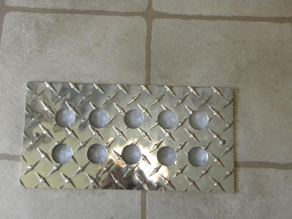
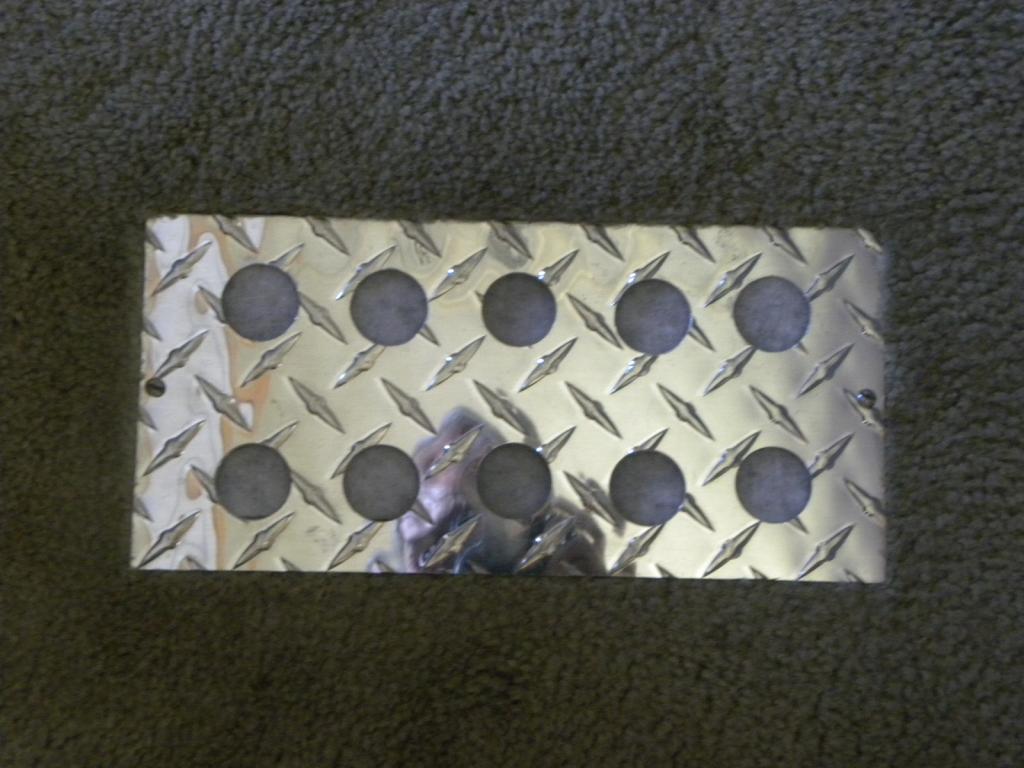
The floor grates for the trailer's heater vents were beat up so I made new ones out of the scrap. pieces.
-
I'd pop the top of the case off and check it out. If a bearing went out you'd think you would hear it grinding for a while before it took a dump. Also if the input shaft (4th gear) bearing went bad and went to pieces it wouldn't mesh with the counter shaft properly and you'd lose 1ed and 2ed . Could it be that the shift rail or sliding hub for 3/4 selection jammed up due to a broken synchro ring or dog? I've rebuilt a few 4 and 5 speed trans over the years and like the others have said it's not hard and it's not brain surgery. If you take your time and pay attention to details with a few hand tools and a gear puller you'll be able to due it.
-
Do you have room to comfortably carry portable solar panels in your truck camper when traveling? In a 30' travel trailer there is room inside or in a basement compartment to store it but how much room in a cab over truck camper?
-
Check out this site and use the side arrows for other articles on solar. http://www.truckcampermagazine.com/camper-tech/systems/installing-a-solar-panel-system-part-1/
-
Thank his Lucky Charms you were there to help that felonious amateur arborist. He must have missed that part on You-Tube Well who do you think is paying for his medical care? I think it would have been a lot cheaper and less painful if he had hired a tree surgeon and not an orthopedic surgeon. Penny wise, pound foolish.
-
In Mike's diagram terminal 86 of both relays are used to ground them. The black wires join together then a switch is shown. After the switch there is the symbol for ground. The ground can be just about any metal part of a vehicle. Run the ground wire (black) from the relay to a rocker or toggle switch mounted in the dash and then a wire from the switch to a metal bracket under the dash.
-
wire size chart https://www.tessco.com/yts/industry/products/itm/automotive/get_wired.html
-
To the body or chassis https://www.tessco.com/yts/industry/products/itm/automotive/get_wired.html . In the ground wire circuit.
-
Nappa has 1/8 -27NTP tap part № BK T440 for $18.49 and 1/4 -18NTP tap part № BK T-302 for $6.99. drill bit size: 11/32 for 1/8 NTP, 7/6 for 1/4 NTP.
-
I just called the 785-4cables, 785-422-2537, recording came on saying "the Jack customer you have called is unavailable to take your call. Please a message after the tone". So your guess is as good as mine. Can you have them made locally? In my area there are two battery shops that will make starter, ground or RV cable to specifications.
-
A very nice write-up!
-
I know a guy in Idaho that has 3 of them sitting in his yard right now that are ripe for the picking.
-
If it is a drum axle you would need an EGR rear brake conversion kit. An added pita, I don't think it's worth it .
-
I found one on E-BAY but it may be for drum brakes. http://www.ebay.com/itm/2000-2001-Dodge-Ram-2500-Diesel-Spicer-Dana-80-Rear-Axle-limited-slip-New-Oem-/121937623247
-
Right. Dana 70U axles have 32 splines and were fitted in most 2ed gens. A Dana 70 has 35 spline axles.

