


IBMobile
Staff
-
Joined
-
Last visited
Everything posted by IBMobile
-
2 wheel drive front Hub Bearing HD2500/3500 Nut 280 Ft Lbs.
-
No, it's like what you've done to silence the alarm sounding the horn; this is just another work around. I think the only way to fix this horn problem, if the foil wrap doesn't work, is to replace the central timer module.
-
I gave this problem some thought and came up with cutting the wire to the central timer that grounds the horn relay.
-
Disabling Factory Alarm Horn Are you tired of the factory alarm horn going off with 3 honks (tamper alert) when unlocking the door or at other inconvenient times? The horn sounds when the central timer module grounds pin 85 of the horn relay. Here is a simple inexpensive remedy to stop the module from sounding the horn. You cut the wire to the module; the horn will still work at the steering wheel horn button but not with the door locks or key fob. You will need a phillips screwdriver, small wire cutters, and a roll of electrical tape. Remove the three phillips screws at the bottom of the panel under the steering column and pull the panel off, this will allow you to see the central timer module under the dash and to the right side. by joeld79 Find the C2 connector; this will be the white one. You can remove it from the module by pushing the small tab, located in the center of the connector, in and pulling down. Now find the black wire with red tracer that terminates at pin 18 of the C2 connector and cut it leaving about 2-3”; this will allow enough wire if you need to rejoin it at a later time. Finish by wrapping the ends of the wire with the electrical tape; push the connector back into the module, and install the panel. There are no guaranties implied or expressed. Written by: J. Daniel Martin AKA IBMobile 12/10/2019 View full Cummins article
-
Disabling Factory Alarm Horn Are you tired of the factory alarm horn going off with 3 honks (tamper alert) when unlocking the door or at other inconvenient times? The horn sounds when the central timer module grounds pin 85 of the horn relay. Here is a simple inexpensive remedy to stop the module from sounding the horn. You cut the wire to the module; the horn will still work at the steering wheel horn button but not with the door locks or key fob. You will need a phillips screwdriver, small wire cutters, and a roll of electrical tape. Remove the three phillips screws at the bottom of the panel under the steering column and pull the panel off, this will allow you to see the central timer module under the dash and to the right side. by joeld79 Find the C2 connector; this will be the white one. You can remove it from the module by pushing the small tab, located in the center of the connector, in and pulling down. Now find the black wire with red tracer that terminates at pin 18 of the C2 connector and cut it leaving about 2-3”; this will allow enough wire if you need to rejoin it at a later time. Finish by wrapping the ends of the wire with the electrical tape; push the connector back into the module, and install the panel. There are no guaranties implied or expressed. Written by: J. Daniel Martin AKA IBMobile 12/10/2019
-
Try checking the connections at the PCM. All of these codes have the PCM in common. The transmission codes also have the connection on top of the transmission in common, For the P500 after checking at the PCM check the connection at the rear axle speed sensor and the connector for the cab at the outside fire wall , lower left.
-
I have to agree with @dripley about the P1688 code. I think that's the code my VP44 set when it died. You should run the Blue Chip Diesel VP44 diagnostic tests to verify if the pump is good or not. https://www.bluechipdiesel.com/runningtests This is how I've wired my fuel pump using the ECM as the trigger with no restore needed.
-
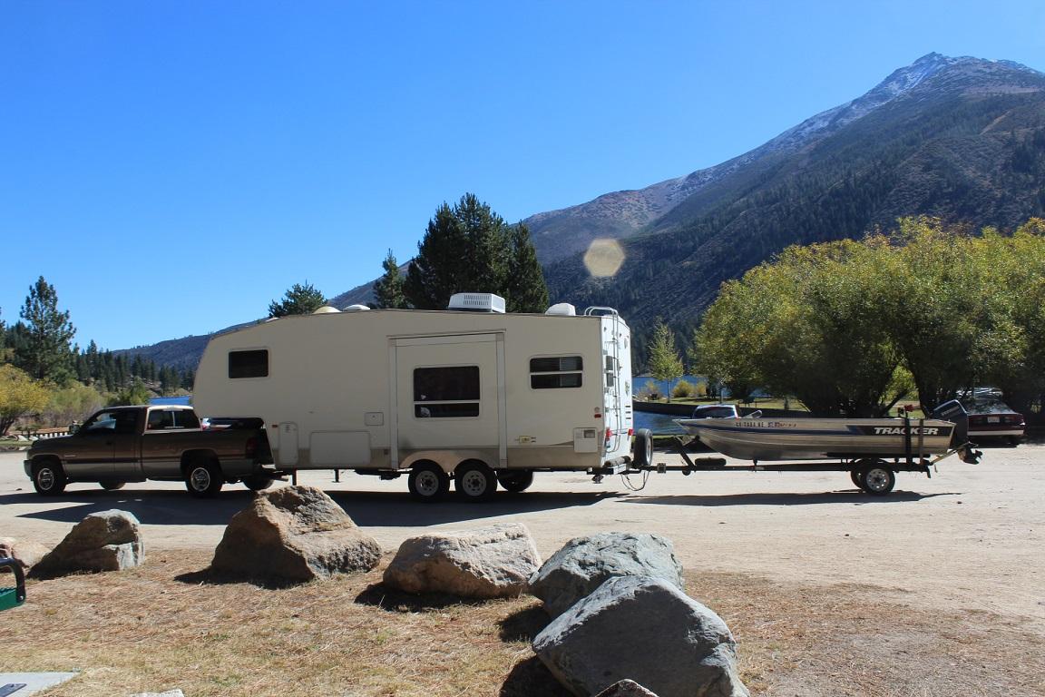
@JAG1, Sorry to here about your troubles with the HP laptop and @Alexio Auditore's problem with a slow operating system. I'm working off an HP Pavilion for the last 2.5 years, I know HP = POS but a customer gave it to me new in the box as a tip. I think it is a Costco special for around $500. JAG1, you mite have seen it on the table in my 5er when were camping . I use it for internet research for both my business and trip planning, streaming video to my flat screen, and has my repair manuals with wire diagrams; zero problems.Who are you calling geriatric? I've seen @Ed ke6bnl's truck when I was camping last October. It is one nice clean rig.You will have to remove the front oil pan bolts to install the pump's mounting bracket. When you put the bolts back in be sure to torque them to 18 Ft. Lbs. to avoid any oil leak.Muffler shop...wield in delete pipe... inexpensive...done.Check out Amazon for the in line strainer. They are a couple of dollars more but with Prime it's free shipping. The Baldwin pf7977 filter can be had there for $15 each and free shipping with Prime.There has been several conversations this year about which oil to use in the nv4500 transmission; here are 2 of them . I hope this helps,That is the reason this inexpensive rear view camera/monitor do it yourself system was designed. Since it can be on all the time while driving it is very useful, even when not towing the boat behind the 5th wheel, for lane changing, backing up, and seeing who or what is behind the trailer.
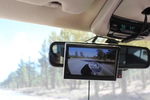
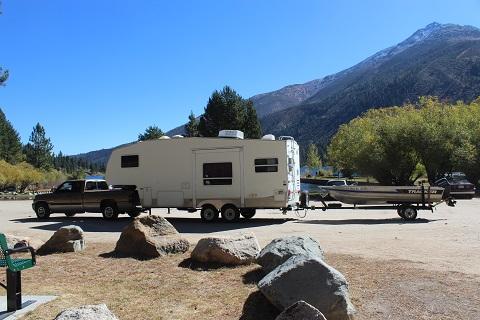 That looks like all the lines you'll need and an inline filter should be installed on the power steering box return line.Mechanical with electric pump disabled, fuel strainer, and factory filter.Check the transmission relay that it's sending power to the trans. If that's OK then the governor pressure solenoid or transducer may not be working.Review Monitor Cab Monitor and Rear Trailer Camera Parts list: 50’ roll outdoor Cat-5/Cat-6 cable (Home Depot) 10’ red 18awg 1’ black 18awg 10 ‘split wire loam tubing ¼ diam. 5” color monitor (5” E-KLIN 12-24V car monitor, Amazon) Color camera (E SKY EC170-11, Amazon) 4 pin round trailer wire connector ON/OFF switch, SPST, push or toggle 2 amp fuse Fuse holder Rosin core solder Electrical tape Heat shrink tubing Coaxial cable staples Zip ties 2”x4”x ½”- ¾” plywood or board Flat black spray paint Double sided tape or 3M auto molding tape Clear silicone adhesive 3 #6x ½” screw 1 #8 ring terminal 22-18awg Tools: Wire cutter Wire stripper Pliers Solder gun Small blade screwdriver Phillips screwdriver Drill motor Drill bits ⅛ - ⅜” Hole saw 1⅜” Hammer This system was put together in the spring of 2017 and has been used for over 20,000 miles with no problems. It cost about $80 for the cable, monitor, switch, round 4 pin trailer connector, and camera. The rest of the parts and materials I had on hand. I put in the ON/OFF switch so the monitor can be turned off for night driving. Note: Cameras with inferred night vision may not work well at night if the camera is placed inside the trailer and viewing through glass without outside lighting. Installing Camera and Trailer Wiring First, locate a suitable mounting position for the camera. A rear facing window is ideal and if there is a cabinet next to it the wire connections can be hidden in it. If a rear window is not available a hole drilled through the rear wall next to where the camera will be mounted or the cable run under the trailer and up the outside of the rear wall is an option. Camera mounted in rear trailer window. Run the Cat-5 cable through the trailer from next to the trailer’s seven pin connector, in front, to where the camera’s mounting position will be, leaving 6”-12” of extra cable at the ends, If you have 20’ of cable left you can use it for the truck installation otherwise you will need to buy more. You can drill holes, just big enough, in the walls and floor to pass the cable through. When drilling through the floor be careful not to drill into a holding tank, waterline, or anything else; drilling into an empty storage compartment is best. The Cat-5 cable can be held in place with coaxial cable staples for the walls and zip ties elsewhere. The Cat-5 cable has four sets of 2-24awg: orange, green, blue, and brown. I used the orange set for 12volt feed, the green for the ground, the blue for video signal, and connected the shielding wires from the camera and monitor to the brown. Spray paint the wood black and let dry, attach the camera to the wood with the 2 #6x ½” screws. Solder camera’s: power wire to the Cat-5 orange wires, ground wire to the Cat-5 green wires, video to the Cat-5 blue wires and shielding to the Cat-5 brown pair; sealing each solder joint with heat shrink then wrap cable junction with electrical tape. If the camera is next to a cabinet you can run the wires through a hole drilled in its bottom or side and place connection in the cabinet for concealment. Now, place the two sided tape on the wood and carefully affix it to the window with the camera facing out. Camera view adjustment will be done after the monitor is functional. Installing Monitor and Cab Wiring In the truck cab remove the overhead light counsel and drill two holes in it, see picture; one for the monitor power cable and one for the monitor video cable. Do not remove the cover for the garage door remote pocket, just open it up and remove the square button; you will be passing the cable from the monitor though here. You can install the ON/OFF switch in this area at this time or locate a place that is to your liking. Find the roof bracing and drill a small hole for a short screw that the systems ground wire will be attached to. DO NOT drill through the roof. Find a wire that has switched power to splice into for the systems power. Power draw is about 1amp. Add a 2amp fuse to the red wire and spliced it to the tan wire at the large connector under the left side of the dash between he park brake pedal and the firewall. This tan wire is rated 20amps and is used for the power windows. Picture by Leaky88 You will need to remove the trim cover for the left A-post and drop the left sun visor. The red wire with the Cat-5 cable is run up the left side of the dash, A-post, and between the head liner and roof to the center counsel area. The switch can now be attached to the fused red 18awg wire. On the other side of the switch attach another red wire and solder the free end to the orange Cat-5 wires and the monitor’s power wire. Using the 12” piece of black wire, solder the green Cat-5 wires and monitor’s ground wire to it; attach the other end of the wire to the roof brace with a ring terminal and screw. The video monitor signal cable is solder to the Cat-5 blue pair with the shielding soldered to the Cat-5 brown pair. Heat shrink is used to insulate connections. Install the modified overhead center counsel, sun visor, and A-post cover. Using the suction cup mount attach the monitor to the rear view mirror and run the monitor cables into the center counsel through the square hole that was used for the garage door remote and connect to the system cables. Route the rest of the Cat-5 cable through the left side of the fire wall via the wire grommet, down the left outside fire wall and along the inside of the left frame rail attaching it to the wire harness with zip ties. Find where the round 4 pin plug would work best for your set up. On my truck it was next to the 7 pin trailer connector in the bed side wall. 4 pin round video connector next to 7 pin trailer connector. Drill a hole using a 1⅜” hole saw, that is just a little bigger than the 4 pin round connector, check the size of your connector before drilling; run the Cat-5 cable from under the truck bed through the hole. Attach the cable wires to the male 4 pin round connector but DO NOT screw the male plug to the truck until testing is completed. With the Cat-5 cable running alongside the 7 wire trailer cable attach the female side of the 4 pin round connector to the trailer’s Cat-5 cable leaving the cable a few inches longer than the 7 wire trailer cable. Be sure the wires going to the 4 pins of both ends match up color to color. Rear view monitor with forward view dash cam. Plug the two ends together and turn the power on. The monitor will illuminate and show the view out the back of the trailer but the camera will need to be adjusted horizontal and vertical. Horizontal adjustment is done by loosening the front of the camera by turning its outer cover counterclockwise; this allows the camera to be rotated to get a level view. Vertical adjustment is done by bending the bracket slightly up or down. Two people with radios make this easy. When testing is finished seal the back of the 4 pin connectors with a dab of clear silicon sealer and slide the male connector into the hole and secure with 2 sheet metal screws ¼” x 1”. The exposed Cat-5 cable coming from the trailer can be covered with ¼” split wire loam tubing and secured to the larger trailer cable with zip ties. If you have a bumper pull trailer a bracket can be made out of sheet metal or angle iron and attached to the trailer hitch. When the monitor is not being used it is cover with the bag it came in, placed back in its’ box, and store in the center arm rest. Read through this a few times and have all materials and tools before starting. There are no guaranties implied or expressed. Written by: J. Daniel Martin AKA IBMobile 11/29/2019 View full Cummins articleReview Monitor Cab Monitor and Rear Trailer Camera Parts list: 50’ roll outdoor Cat-5/Cat-6 cable (Home Depot) 10’ red 18awg 1’ black 18awg 10 ‘split wire loam tubing ¼ diam. 5” color monitor (5” E-KLIN 12-24V car monitor, Amazon) Color camera (E SKY EC170-11, Amazon) 4 pin round trailer wire connector ON/OFF switch, SPST, push or toggle 2 amp fuse Fuse holder Rosin core solder Electrical tape Heat shrink tubing Coaxial cable staples Zip ties 2”x4”x ½”- ¾” plywood or board Flat black spray paint Double sided tape or 3M auto molding tape Clear silicone adhesive 3 #6x ½” screw 1 #8 ring terminal 22-18awg Tools: Wire cutter Wire stripper Pliers Solder gun Small blade screwdriver Phillips screwdriver Drill motor Drill bits ⅛ - ⅜” Hole saw 1⅜” Hammer This system was put together in the spring of 2017 and has been used for over 20,000 miles with no problems. It cost about $80 for the cable, monitor, switch, round 4 pin trailer connector, and camera. The rest of the parts and materials I had on hand. I put in the ON/OFF switch so the monitor can be turned off for night driving. Note: Cameras with inferred night vision may not work well at night if the camera is placed inside the trailer and viewing through glass without outside lighting. Installing Camera and Trailer Wiring First, locate a suitable mounting position for the camera. A rear facing window is ideal and if there is a cabinet next to it the wire connections can be hidden in it. If a rear window is not available a hole drilled through the rear wall next to where the camera will be mounted or the cable run under the trailer and up the outside of the rear wall is an option. Camera mounted in rear trailer window. Run the Cat-5 cable through the trailer from next to the trailer’s seven pin connector, in front, to where the camera’s mounting position will be, leaving 6”-12” of extra cable at the ends, If you have 20’ of cable left you can use it for the truck installation otherwise you will need to buy more. You can drill holes, just big enough, in the walls and floor to pass the cable through. When drilling through the floor be careful not to drill into a holding tank, waterline, or anything else; drilling into an empty storage compartment is best. The Cat-5 cable can be held in place with coaxial cable staples for the walls and zip ties elsewhere. The Cat-5 cable has four sets of 2-24awg: orange, green, blue, and brown. I used the orange set for 12volt feed, the green for the ground, the blue for video signal, and connected the shielding wires from the camera and monitor to the brown. Spray paint the wood black and let dry, attach the camera to the wood with the 2 #6x ½” screws. Solder camera’s: power wire to the Cat-5 orange wires, ground wire to the Cat-5 green wires, video to the Cat-5 blue wires and shielding to the Cat-5 brown pair; sealing each solder joint with heat shrink then wrap cable junction with electrical tape. If the camera is next to a cabinet you can run the wires through a hole drilled in its bottom or side and place connection in the cabinet for concealment. Now, place the two sided tape on the wood and carefully affix it to the window with the camera facing out. Camera view adjustment will be done after the monitor is functional. Installing Monitor and Cab Wiring In the truck cab remove the overhead light counsel and drill two holes in it, see picture; one for the monitor power cable and one for the monitor video cable. Do not remove the cover for the garage door remote pocket, just open it up and remove the square button; you will be passing the cable from the monitor though here. You can install the ON/OFF switch in this area at this time or locate a place that is to your liking. Find the roof bracing and drill a small hole for a short screw that the systems ground wire will be attached to. DO NOT drill through the roof. Find a wire that has switched power to splice into for the systems power. Power draw is about 1amp. Add a 2amp fuse to the red wire and spliced it to the tan wire at the large connector under the left side of the dash between he park brake pedal and the firewall. This tan wire is rated 20amps and is used for the power windows. Picture by Leaky88 You will need to remove the trim cover for the left A-post and drop the left sun visor. The red wire with the Cat-5 cable is run up the left side of the dash, A-post, and between the head liner and roof to the center counsel area. The switch can now be attached to the fused red 18awg wire. On the other side of the switch attach another red wire and solder the free end to the orange Cat-5 wires and the monitor’s power wire. Using the 12” piece of black wire, solder the green Cat-5 wires and monitor’s ground wire to it; attach the other end of the wire to the roof brace with a ring terminal and screw. The video monitor signal cable is solder to the Cat-5 blue pair with the shielding soldered to the Cat-5 brown pair. Heat shrink is used to insulate connections. Install the modified overhead center counsel, sun visor, and A-post cover. Using the suction cup mount attach the monitor to the rear view mirror and run the monitor cables into the center counsel through the square hole that was used for the garage door remote and connect to the system cables. Route the rest of the Cat-5 cable through the left side of the fire wall via the wire grommet, down the left outside fire wall and along the inside of the left frame rail attaching it to the wire harness with zip ties. Find where the round 4 pin plug would work best for your set up. On my truck it was next to the 7 pin trailer connector in the bed side wall. 4 pin round video connector next to 7 pin trailer connector. Drill a hole using a 1⅜” hole saw, that is just a little bigger than the 4 pin round connector, check the size of your connector before drilling; run the Cat-5 cable from under the truck bed through the hole. Attach the cable wires to the male 4 pin round connector but DO NOT screw the male plug to the truck until testing is completed. With the Cat-5 cable running alongside the 7 wire trailer cable attach the female side of the 4 pin round connector to the trailer’s Cat-5 cable leaving the cable a few inches longer than the 7 wire trailer cable. Be sure the wires going to the 4 pins of both ends match up color to color. Rear view monitor with forward view dash cam. Plug the two ends together and turn the power on. The monitor will illuminate and show the view out the back of the trailer but the camera will need to be adjusted horizontal and vertical. Horizontal adjustment is done by loosening the front of the camera by turning its outer cover counterclockwise; this allows the camera to be rotated to get a level view. Vertical adjustment is done by bending the bracket slightly up or down. Two people with radios make this easy. When testing is finished seal the back of the 4 pin connectors with a dab of clear silicon sealer and slide the male connector into the hole and secure with 2 sheet metal screws ¼” x 1”. The exposed Cat-5 cable coming from the trailer can be covered with ¼” split wire loam tubing and secured to the larger trailer cable with zip ties. If you have a bumper pull trailer a bracket can be made out of sheet metal or angle iron and attached to the trailer hitch. When the monitor is not being used it is cover with the bag it came in, placed back in its’ box, and store in the center arm rest. Read through this a few times and have all materials and tools before starting. There are no guaranties implied or expressed. Written by: J. Daniel Martin AKA IBMobile 11/29/2019I found the Hobbs switch to be a PIA to set when the fuel pressures between the two pump is close. The power to the electric pump has been turned off by removing the fuse and is only used to bleed the system after a fuel component has been changed. The engine starts fine with only the Fuel Boss.Do a cooling system pressure test like @Tractorman recommended. You can have the use of a cooling system pressure tester from O'Reilly tool loaner service for free. You needed to put a deposit down but you will get it back when you return the tool. https://www.oreillyauto.com/detail/b/evertough-4771/tools---equipment-16488/tools-23747/rental-tools-16837/rental-tools--air-conditioning---cooling-19163/26fcb01856e7/rental-tools-evertough-radiator-cap-test-kit/67085/4700282 For the harder to see areas behind the head you can use a small mirror and flash light. https://www.harborfreight.com/search?q=inspection mirrorYes, that will work but you want to use a 12 volt single poll double through switch (SPST) also called an ON/OFF/ON switch. If you can't find a SPST switch a double poll double through (DPDT) switch will due.
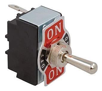 Here it is,


