


Haggar
Unpaid Member
-
Joined
-
Last visited
Everything posted by Haggar
-
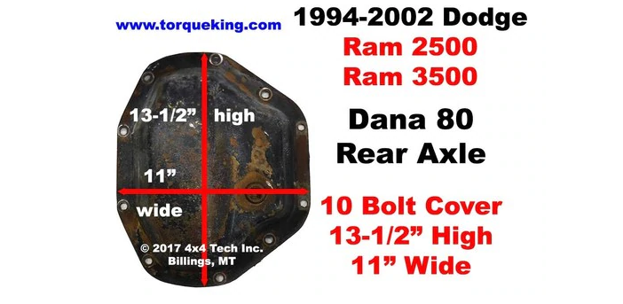
Wil, Keep looking. The diesel 2500 rams with manual transmissions got the Dana 80, which would be your single rear wheel 3500. The automatics got the Dana 70u, which is still not a terrible differential. It can be hard to tell visually the difference as the rear cover looks very similar. Look for the number 80 cast into the housing. Hag

-
Brian, If you don't mind give us a list of what functions now work and what doesn't. Look in the downloads section. (look at the top of the page it should say "forums" "Articles" then Downloads. The full 2001 factory service manual should be there. Use the wiring section (8w) to help yourself slowly trace it out. The module under the dash is the central timer module. The PCM is on the firewall on the passenger side. The PCM is responsible for voltage control. (what you did should be really far from damaging the alternator, but I guess if the PCM is not communicating, it may not regulate charging.) If your batteries are too discharged all kinds of weird things can happen. Get them charged up. GL Hag
-
Brian, Here are the fuses that control the radio and ccd bus. Hag 2001 FSM Ram 8W-18-2.pdf 2001 FSM Ram 8W-47-2.pdf
-
Brian, It could go easy. By pulling the radio out and just disconnecting those wires, you might go right back to normal. (totally depends on what they got connected to.) Or you might have to trace out other items that may have gotten upset or damaged. I hope it is scenario 1. scenario 2 isn't the end of the world, but it will take time to trace problems. GL Hag
-
I have attached the FSM page. (wow mike you are fast....!!!) There was a connector at the radio that goes to the CTM (central timing module) This is connected to the CCD bus (which is the network that connects all the computers in the vehicle together) These should not be connected to anything now. If you did connect them to something, you need to tell us what they were connected to and see if people that are familiar with the CCD network help you find what else may have been damaged. GL HTH Hag 2001 FSM Ram 8W-47-4.pdf
-
I have attached the FSM page. There was a connector at the radio that goes to the CTM (central timing module) This is connected to the CCD bus (which is the network that connects all the computers in the vehicle together) These should not be connected to anything now. If you did connect them to something, you need to start a new thread explaining what was done during the radio install and see if people that are familiar with the CCD network help you find what else may have been damaged. GL HTH Hag 2001 FSM Ram 8W-47-4.pdf
-
The radio could be the problem..... DId the problems start with the radio? According to the FSM The radio is connected to the CCD bus. Going to post some pages here soon.
-
Brian and mike. I suggest starting a new thread. (or peeling this into a new thread.) and we need to get some basic terminology straight. You say it won't turn over, but it is fuel related..... So are you really saying it cranks but doesn't start? or it doesn't crank?
-
I just looked on rock auto. coated cardones are 30 bucks and go up from there. (high core but send the core in...) kit is really 3 something. not sure what is needed to go gen 3. (their calipers seem to be more expensive and show different part numbers than ours. so if your going gen 3 get new calipers they may be different) new brackets for an 03 (I assume that is the 3rd gen) are about 20 each. Hag
-
If time is not an issue, rebuild it yourself. rebuild Kit is like 5$ rebuilt caliper is $30 or so. So there is money to save and experience to have. GL Hag
-
Not sure how to start this so gonna jump in. You can't use the sidewall information, as that is a metric for catagorizing tires. These dimensions change the moment a tire touches the ground. The number you need (and it is rarely given up front, but most tire manufacturers list this data somewhere) is the number of revolutions per mile that tire will have (or they will give you the "loaded diameter" or "rolling radius"). The reason for this is our tires are not round when loaded. How much they change is dependent on the inflation pressure, temperature and the amount of actual load. This is where/how the tire manufacturers calculate the contact patch for a given tire. So just be careful when looking at some of the charts. Many of them are just the mathematical theoretical diameter converted to circumference and given. The tire manufacturers have better numbers on their tires for approximate rolling radius. HTH Hag
-
I think a lot of us have the same wire not connected. No one has ever figured out where it goes and why, that I know of. don't worry about it, or ground it if it pleases you. HTH Hag
-
A quick check is look at the high side pressures (if you have the gauges) (you really needed to do this before swap and after) Short story: try running water on the condenser. Do your vent temperatures go down? if they do go down greatly, you are not pulling enough air through the stack at idle. (Or try an electric booster fan near the top of the condenser) (oh actually if the ambient air is not too high, a leaf blower worked at bringing duct temps down.) An interesting note, we are arguing about lockup. we should be nowhere near lockup, so how much are does the fan clutch pull during partial lock conditions (and is it linear as it locks?). (of course the clutch manufacturers don't publish ANY of that data.... but it is important data to those who need it...) Long story (ok REALLY LONG story) Just went through this issue on another engineer's '05 duramax. Being as we have data loggers available to us, we played with recording ambient temperatures, pre/post evaporator temperatures, approximate stack temperatures, high and low refrigerant pressures, vent temperatures and in-cab ambient temperatures. We used an anemometer to try and get average air velocities. (of course we had no data to compare that too, which would have been nice because it would possibly have shown the problem earlier.) All TSBs for poor A/C performance for the duramax were around making sure the airflow through the stack was clear of obstructions and that all plastic bits were in place making sure the air went through the stack, not around the stack, into the fan. (so air flow across the condenser seems to be a common issue) We have in the last 2 years replaced every component in the ac (yes the evaporator too!) chasing this issue... only did the data acquisition in the last 3 months. The problem now was the fan clutch. It would just not pull enough air through the stack during idle. (we don't know what the original problem was.... the symptoms have always stayed the same throughout, but maybe it was the fan from the very beginning and the "new" fan clutch was not any better and possibly worse....) Basically we were able to diagnose that his AC worked fine above about 15mph. The minute you went below this speed, the high pressure side started sliding high, dragging the low pressure side with it. We could get it to bounce off of the high side pressure switch...... That should never really happen in a properly designed and configured system. We shotgunned the last fix. We replaced the fan clutch and put the suburban condenser on (the suburban condenser due front and rear AC evaporators has about a 20% increase in surface area. Present data is outstanding. I think he is still a bit low on freon (we have not charged the system by superheat yet. We just made an ewag off of volume change) Our pre and post evaporator thermocouples may not be in perfect places (we didn't think to install them while the hvac box was out) . According to the acquisition with the AC on recirc, he is seeing almost a 40f delta T. HTH GL Hag
-
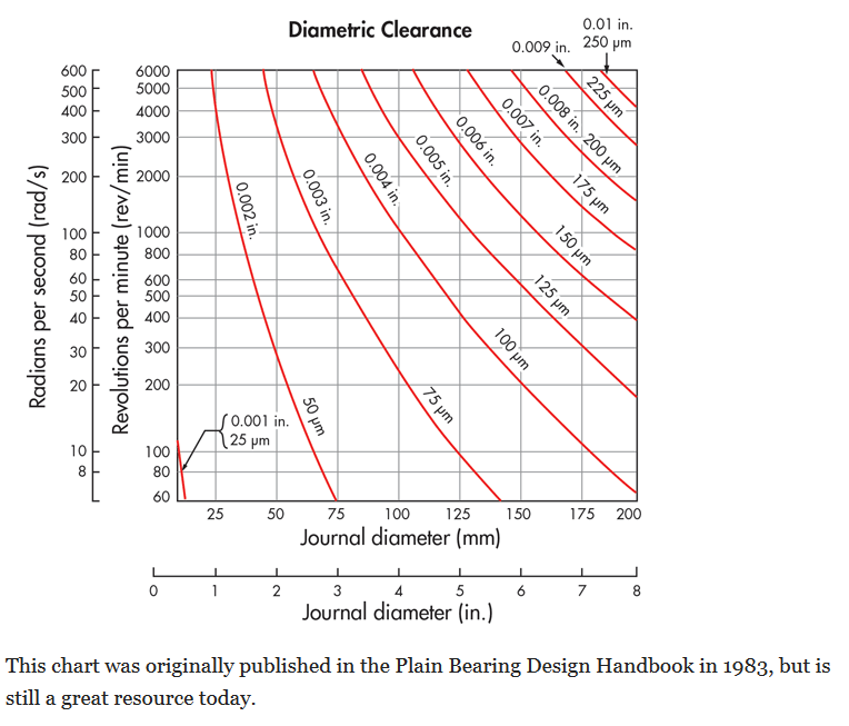
Katoom, I agree, the "no movement" is a non-sequiter. (no movement would be just that it wouldn't move.) I have looked many times for true clearances for yoke and bushing for our application. I have found it no where. (even for the old power slide... no one goes into enough detail to give the dimensions in 3 or 4 decimals.) Here is a standard chart for plain bearing / shaft running clearances. Our application is dead on the 0.003" Diametral line. a bit over 2" yoke diameter (i think its considered 2.2) and nearly 3000 rpm (ok a bit more in OD. call total clearance 0.00325") So it should be approximately 0.0015" clearance per side. ( this chart may get modified later for thermals and other things, but this is a good starting point.) So I can kind of see an answer of "no movement" by someone that is not into machine design. A better non answer would have been almost none. You presently have more than 0.0015" to 0.0020" per side clearance. HTH GL Hag
-
we need more of the story. is the truck new to you recently? did it run right at some time before the mods? its p-pumped. ignore a tps code. was the trans installed before the p-pump so it is pcm/ecm controlled and now those signals are irrelevant (and probably non existant?) I am no auto man but the reason to p-pump is to get rid of the computers. so you would want a trans built for a pre-98 truck to work with it. again i am totally ignorant to the automatic world in these trucks, but I gather post 98.5 autos look for information from the computers. GL Hag
-
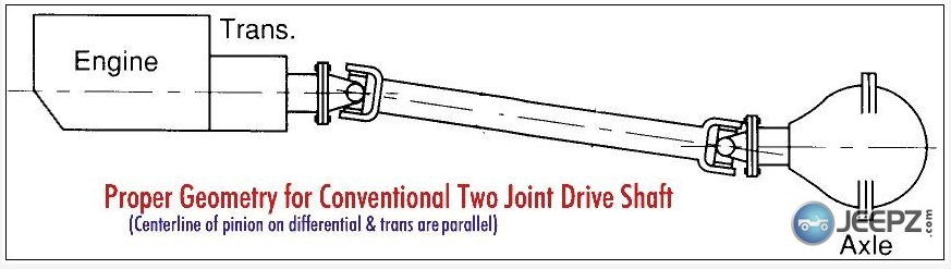
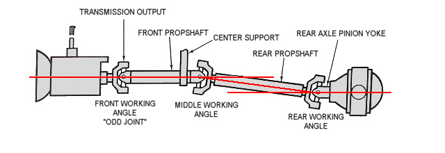
Katoom, I figured it was a one piece. You have a significantly larger wear area on the yoke from the seal than I do. In a one piece shaft your tail shaft bearing plays a more significant role in yoke location (and more important the instant center during rotation). One also has to remember, due to the gear ratio (torque multiplication) the pinion would much rather rotate AROUND the ring gear than turn the ring gear. Yes picture that. un-restrained, the tires would sit still and the axle housing would spin around the ring gear. Our rear suspension prevents the axle housing for doing this, but the forces that want to do this are still in the system and must resolve themselves. Some of this force is in the upward and downward movement of the nose of the rear axle. (upward during acceleration or carrying the load, downward under off throttle unloaded decel etc) Now picture the side view of the rear axle, driveshaft and TC output. Begin rotating the rear axle about the wheel center line. What does the yoke do? It has to move out of the TC. Depending on how you imagined the relative relationship of the TC and pinion yoke (you should have imagined them in a parallel offset configuration) the yoke not only slid in and out, but it rotated up or down a little bit about its own physical center. (the yoke tries to move in only a lateral line, but there is an angular component that is unresolved.) In your mind picture pulling a pin out of a tight hole. The best way is to pull it straight. If you pull it at an angle, what is the pin going to try to do, it will try and pivot in the hole to meet the direction of force and "drag" on a side. This is how the tail shaft bushing wears out. In a carrier bearing drive shaft (now it has a bunch of its other problems) the tail shaft AND the output yoke have the same reference to the frame. so any movement of the yoke is closer to straight in and out. The carrier bearing is what sees the brunt of the angular issues and reduces the wear on the tail shaft bushing. This picture doesn't show it, but there is a slip joint near the middle working angle on our 2 piece drive shafts. So most of our torque thrust and angular issues are resolved there, leaving the tail shaft bearing to only support the weight and keep it in line. The reason I brought this discussion up, is to explain why you would have a tail shaft bushing issue MANY moons before I should (and I have already replaced mine). Your tail-shaft sees much more work than mine in exactly the same conditions. The reason you don't have a vibrational issue that you can feel yet is the item you are displacing is the TC output shaft. The output shaft's radius of gyration and associated mass in the system is extremely small. (the drive shaft is the elephant in the room) Since the drive shaft is well balanced, the fact that the instant center during thrust is different is not enough to disturb the rotational balance. If you need to, hook the go-pro to the frame and run some video of the pinion and then some of the TC output during the same loop on the road. I have used that in the past to solve some vibration issues before. Its kinda neat. I hope this made sense and helps.... Hag
-
Katoom, Dang it. I was hoping vent really. That would be easily explained with operating temps unloaded vs loaded. so nix that one. The NVs usually have a pump in the TC that spray oil to the tail shaft bushing. (I only know this from the GM NV t/c's but I assume (and they refer to it in our FSM) they have the same on ours.) So only if you are really low on fluid, would there not be oil circulating to the tailshaft bushing. So I think that circles us back to loading (or torque application) changing the position of the yoke in the tail housing. Since you are a short bed, are you running a 1 piece or 2 piece drive shaft? GL Hag
-
Katoom, One thought is could your TC vent be pinched or plugged? (it should be on the firewall near the vacuum lines that go to the TC for the CAD to operate) Another thought, I need to do some more research, but some cross sections of radial seals (seal designs) are limited to very small shaft to bore mis-alignment ( as low as 0.005") and total dynamic runouts of as little as 0.003" I agree New Ventures engineers should not have used a design that needed to be that precise, but..... If it is not the vent, and the surface of the yoke is good and not damaging the seal, and you are not dragging foreign materials into the seal to damage it, it has to be "runout" killing it. I agree at any instant in time, it is not run-out, but loaded vs unloaded is forcing it to operate in different locations, so your shaft to bore misalignment is a constantly changing number, based on ride height and load being applied. (this means while pulling the camper up the hill it operates in one position, coming down the hill it is operating in a totally different position. I truely believe that if you have ruled out the other items, it has to be the inability of the bushing to hold the yoke centered. HTH Hag
-
I am not sure if you like junk yards much, but a suggestion.... Look for vacuum solenoids from the fuel vapor system from a wrecked car. I am not sure if the UK versions use them (but I am pretty sure they did) but in the USA we have to capture the fuel vapors from the tank in a carbon structure, and burn them at a later time. not certain that it will work for you but it should. I think due to its internal valving if you put it in the 4wd side of the cad, if you wanted 4wd, you would need to actuate it. (I think it is normally closed, and the downstream vents to atmosphere in the non actuated state) but it would make it not an under truck or hood adventure. Hag
-
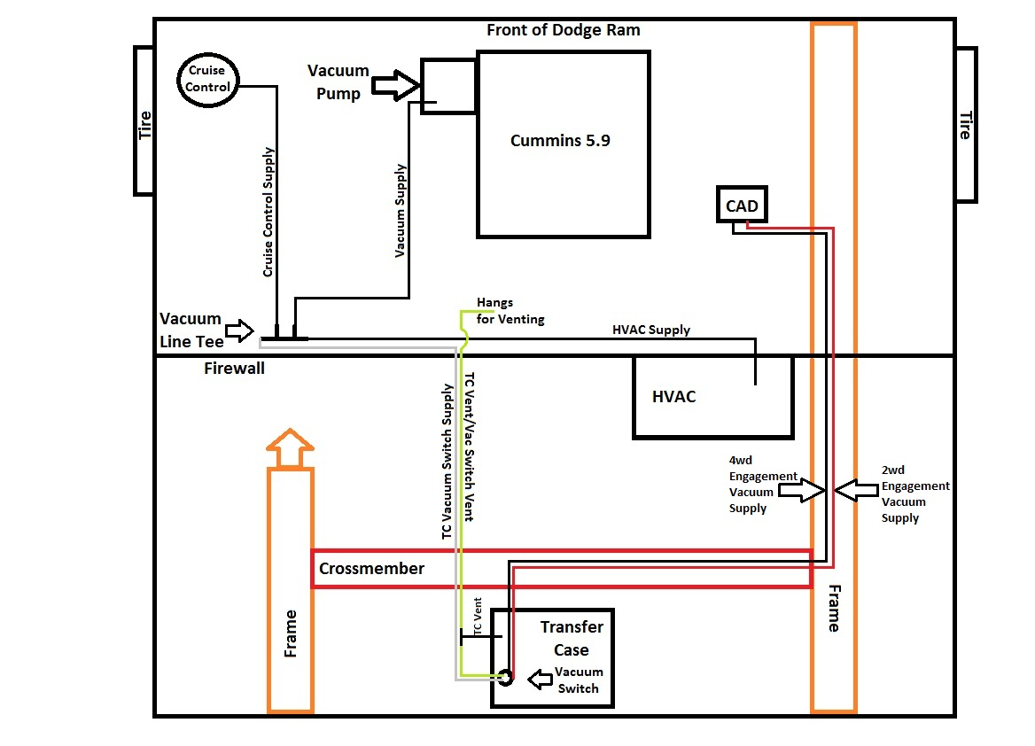
Wil, Until you get to the full blown mod, there are 2 ways to make the CAD not connect for you. 1. Open hood. Locate vacuum hose feeding the switch in the transfer case. (should be on firewall near the drivers side. in a "tee" going vertically down. Disconnect this line. Use a vacuum cap (easy to get at a zone near you) to plug the tee. voila your cad will not try to actuate. 2. If you are afraid to open the hood, or it is too far to reach that hose easily, lay under the front end of the truck near the cad (behind passenger side front wheel) (or you can turn wheels fully left and go between the tire and wheel well, I lay a carpet scrap on tire to not get too dirty) Swap the two vacuum hoses on the cad actuator. Just remember you will need to re-swap when you want to go back to 2wd. Here is a schematic of the vacuum. Number 1 way is disconnecting the grey line. number 2 is swapping the black and red. You could also just disconnect and plug the black line from the actuator.(so a 3rd way?) HTH Hag
-
White, My WTS light seems to work properly, but I have noticed that if I am using the key to bump the lift pump but not allowing the engine to start (to bleed air or fill the filter), I will get funny reactions from the WTS light. I am certain that it is a timing issue and giving it confusing instructions. (off on, bump no start, off, on, bump no start) If I give it a few minutes when I go back it is normal. Hag
-
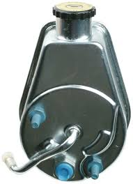
I found the picture of what someone says is the back of a 99 power steering pump. Cant confirm it, (it only has one return line, but I am stuck on the 01 and it has 2 return lines to the reservoir.) but notice the upper left and lower right holes have bolts in them. HTH Hag
-
thats what we are saying. The upper left hole should be filled with a bolt to keep the reservoir attached to the pump body. In non-hydroboost vehicles the lower right one is also a bolt. (big center is the pressure and the return line goes on the tube.) in hydro-boosted vehicles the lower right one should be filled with a special bolt with the other return line. (the steering sector and the hydro boost have separate returns to the reservoir) HTH Hag
-
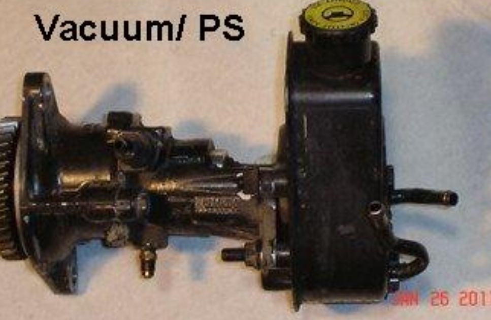
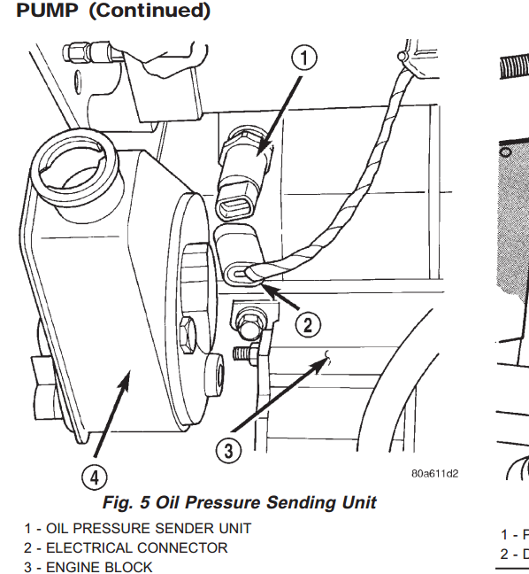
where does your hydroboost return? here is a picture i captured. It looks like a bolt. the FSM shows a bolt in one view too. I don't see both those return tubes on the picture you posted. This is the picture from the FSM showing a bolt also (or bolt head, could be a plug) I hope someone has been here more recently than I have. PS is 5 years behind me.... I just don't remember. GL Hag
-
Just keep an eye on it. It was possible that it pushed out (temperature related volumetric expansion). Not to mention you could have pushed out an air bubble that took it over the top. (especially if you didn't fully bleed the system after re-install) (the ps reservoir cap is a "vented cap" allows for the fluid to expand and contract without building air pressure in the reservoir) Wash it down with brake cleaner and keep an eye. If you get a leak again, clean it up really well (and i mean squeaky clean) cover the pump in flour. start it up and watch closely for where the flour starts turning colors. That will get you closer to where the leak might be. HTH Hag

