Jump to content
  • Welcome To Mopar1973Man.Com LLC

    We are a privately owned support forum for the Dodge Ram Cummins Diesels. All information is free to read for everyone. To interact or ask questions you must have a subscription plan to enable all other features beyond reading. Please go over to the Subscription Page and pick out a plan that fits you best. At any time you wish to cancel the subscription please go back over to the Subscription Page and hit the Cancel button and your subscription will be stopped. All subscriptions are auto-renewing. 

1948 Dodge COE Build


Recommended Posts

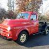
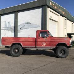
These pictures reflect My "project" as I bought it.  As you can see it has a 440/727 engine/transmission combination.  In addition it is on a 1978 Dodge M300 MH chassis with 17.5 inch wheels.  My intent on buying this was to restore it as a "truck", I'm not into the "slamming school", though I respect the right of others to pursue their vision; there are just too few of these particular trucks to deny them there place in history.  Having said that, I always do what I call a performance upgrade to most of my projects; in this case I have opted to replace the 440/727 with a 1996 5.9BT low miles diesel and a 47re transmission.  Following submissions will include the "teardown" of what became my chassis, then the "fitment" challenges (of which there were/are many).  I do need some help in one area (that I know of), I badly need a 2WD wiring harness, my intent is to use a 96-98 wiring harness which accommodates the 47RE 2WD transmission.  More to follow.


440 1.JPG

440 2.JPG

440 3.JPG

440 4.JPG

Part 2:  As I mentioned previously I wanted to build a truck, the smaller M300 Dodge MH chassis was too small for my objective.  I had seen a 32 foot Executive MH in a local wrecking yard that was built on a 1977 Dodge M500 MH chassis with 19.5 inch wheels which I picked up for $800.00 delivered (so now I have two 440/727 units), also got a low hours Onan 6.5 kw generator which runs great.  These pictures reflect a couple of the steps in demolition, my only concern was not to do damage to the chassis/suspension.  I say to those of you who motorhome; I hope yours is better built than this one was.

RV 2.JPG

RV 3.JPG

RV 5.JPG

RV 16.JPG

RV 21.JPG

RV 24.JPG

RV 32.JPG

Edited by Dodge48
Starting over with better clarification.
  • Like 4
Link to comment
Share on other sites

Part 3:  The pictures below reflect the bare chassis that still has the "outriggers' that supported the extended floors and the long overhang behind the rear axel.  I borrowed the neighbors plasma cutter to make easy work of their removal, also removed about 4ft of the rear overhang (I'm not going to need it because I'm going to be installing a tilt flatbed when I get to that point 9there is enough "tail" there to accommodate placement of the trunions when I get to that stage.  You might notice the sandblast residue from my blasting the frame (both front and rear axels were removed prior to blasting and were "delicately" done separately.  I thank my lucky stars for my tractor, I'm not a young guy and I'm not the hunk I used to be.

010.JPG

New Frame 1.JPG

New Frame 3.JPG

New Frame 4.JPG

New Frame 6.JPG

New Frame 7.JPG

New Frame 9.JPG

New Frame 11.JPG

New Frame 14.JPG

New Frame 15.JPG

  • Like 3
Link to comment
Share on other sites

Nice project, I will be following this! I like the larger M500 chassis you found over the M300. I used a front axle out of a '76 M300 for my '74 F-350 build. It had the twin I beam/coil spring front end but it wouldn't carry the weight of the Cummins. I used everything from the Dodge including the steering box. You do have to drive it tho, I kinda blame that on the weird design of the axle. It has the wishbone knuckle on the axle v/s the spindle. I almost used an axle out of a IHC with the 5 bolt 19.5's, but it had drum brakes so I passed on it, but in hindsight, I wish I would have used it anyway. 


That M500 looks like it has the D-80 axle and the strange front axle as the M300, just bigger. I would guess the axle has 4.88 gears, so the Cummins will need some faster ones. 

  • Like 1
Link to comment
Share on other sites

NIaacs and JAG1, thanks for your interest and comments.  NIaacs, the front axel is an F50 rated at 5000 lbs, you're right, it is simply a heavier version of the M300 axel.  The differential is a Spicer 70HD with a load rating of 10,000 lbs with 4.56 gear ratio; that was another reason for my effort to get the 22.5 inch rims.  The M600 chassis had Rockwell axels with six lugs and significantly greater weight capacities.  I found a set in AZ, I thought the shipping costs were prohibitive - wish I had done it, those wheels are easy to find and you can get them in aluminum.  Thanks again for your interest.


Jag1, thank you.  It seems you are the man behind the site; I am not very proficient on these sites.  I would like to delete my long ago attempt at sharing this which shows up on each of my current posts, can you tell me how to do that?  Thanks again.

Part 4:  Once I was able to get the newly painted frame in my shop I blocked it up in order to install the frong and rear axels and get the chassis back on its wheels.  Once that was accomplished I began the rebuilding of the rear brake drums and had the front rotors turned and rebuilt calipers to install..  I took advantage of the easy access to ifabricate and install new brake lines on the rear axel.  On the subject of brakes, the hydro-boost  system that was on the MH was huge and in need of a major overhaul; I determined that I would not use it on the project  Once I got the chassis on it's wheels I went about mounting the cab.  At that time I was still going down the path of rebuilding one of my 440'/727 units as my power source and I wanted to ensure clearance and where the cab would fit relative to the front wheel openings.  I'll attach some pictures of these efforts.  As you will probably notice is that the cab was to far forward and to high; as I imagine anyone reading this knows, the cab needs to be in proper relationship to the core support; pictures will show that I was way off and had to make some significant changes to the support structure.

029.JPG

031.JPG

Orig Master Cyl 1.JPG

Orig R Brake 1.JPG

Orig R Brake 3.JPG

Redo R Drum 1.JPG

Redo R Drum 4.JPG

Redo R Drum 7.JPG

1 Alighnment 1-2.JPG

Gap 2-2.JPG

1 Assy 1-3.JPG

  • Like 3
Link to comment
Share on other sites

Part 5:  Last session I alluded to difficulty in getting the cab to align with the core support and not be so high as to exaggerate the gap between the top edge of the front fender and the top of the tire (I still had the 19.5 tires on).  In addition the cab was forced into a position that the wheel was not centered in the fender wheel opening.  Taking these alignment problems one at a time I'll first address getting the wheel to center in the fender wheel opening.  Some of you may be aware that the core support in this vintage Dodge truck had a "dogleg" in the vertical portion  of the support; I'm going to attach a picture of the "dogleg" and the modification to correct the problem.  The new core support took three different core supports to fabricate the final product which has a straight vertical orientation.  Secondly, the stock 1977 MH cross member on which the core support was to be mounted on forced the core support to sit to high.  I attempted to correct this by cutting a recess in the cross member and having a large angle iron piece welded in, still not enough.  I then purchased a 3/8 3x4 inch thick angle iron and modified it to take the place of the stock unit.  The combination of eliminating the "dogleg" and fabricating the "new" cross member solved the issue.  

Core Support Mod 1-1.JPG

Core Support Mod 1-2.JPG

Mod Xmember 1-4.JPG

New Xmember 1A.JPG

New Xmember 1D.JPG

Orig Xmember 1-3.JPG

Gap 3-1.JPG

  • Like 3
Link to comment
Share on other sites

That thing is pretty sweet!  Great job so far.  The fresh painted components are purdy.


I'd save lots of budget for sound dampening having that noisy 12 valve under the floor.  I put 3 layers of fat mat on my firewall in my Fummins.  It is much quieter, but is still loud compared to my bride's dually.  Granted I'm running lots of timing and its got over 500,000 miles on it.

Link to comment
Share on other sites

Bacon Creek:  I agree, it has the potential to be loud and hot.  I will install Dynomat (or equivalent).  I plan on wrapping the exhaust from the turbo to the rear of the cab.  If you have knowledge of other good materials that would help mitigate the noise/heat please let me know.  Thanks for your interest


Part 6:  Wheels and tires.  I previously alluded to the difficulty of finding 5 lug 20 inch tubeless wheels; they are out there on vehicles (usually Ford school buses) the owners of which don't want to sell.  I did find two of them in a wrecking yard, I got so excited about the find that I bought them with tires mounted; when the tires were removed it became clear they were not a match, the rim widths were not the same.  Ultimately I decided to move forward to obtain a "matched" 7 wheel set.  Five lug "widow-makers" are plentiful and free to cheap.  I obtained 7 of them and took them apart to obtain an unmolested hub.  This required drilling out 18 rivets, then cutting "V" notches on the inside and outside lips and doing the same on the opposite side of the rim.  Using a hand-held cutoff wheel I carefully cut a groove between the "V"s to weaken the metal between the two lips without cutting into the hub; then using a 10# sledge hammer to break the bond.  This effort gave me 7 good hubs.  I sent the hubs to "American Wheel Specialties" in Kennewick, WA to having new 22.5 inch tubeless rims mounted on the hubs.  The did a great job, sandblasted the hubs, mounted the new rims and primered each unit.  I picked them up in person to ensure that what 'WE' had fabricated was gong to work before taking possession of them - they were great.  I had previously purchased a set (2 steering) and 5 (driver) 22.5 inch tires which I had mounted after painting (I didn't want to tie-up a lot of money in new tires to sit and age while I completed this fairly lengthy project).

002.JPG

003.JPG

004.JPG

Hub 1.JPG

Hub 3.JPG

029.JPG

  • Like 3
Link to comment
Share on other sites

  • 4 weeks later...

Part 8:  It's been quite awhile since I last posted; combination of grandkids activities, weather (2 ft of snow that hung around for days and progress on the project which is pretty detailed.  You probably noticed that most of what I've shared with you is steps taken quite a while ago, pretty much all of them are what I would call gross steps in the process; I've kind of worked myself into more detailed steps toward the finish - a long way to go - had I been candid with myself I'm not sure I would have taken on this project, I've got others in the wings.  You know the old adage "in for a penny, in for a pound"; but, I'm lovin' it.  In this segment I'm making the transition from an engine on blocks to slowly easing it into it's intended resting place (pretty tight), then attaching the 47RE transmission (no cross-member yet).  A couple of the attached pictures show the cab support, the height of which must allow alignment with the core support which was addressed earlier (it all comes down to wheel opening be in a proper relationship with the wheel, both in center and space from the top of the tire to the highest edge of the fender).  I'll try to be more consistent in my posts, I appreciate your interest and comments.  I know I'm still not using the proper format for this, I've got to figure it out.

031G.JPG

028.JPG

025.JPG

024.JPG

022.JPG

026G.JPG

014G.JPG

F Install 2.JPG

  • Like 2
Link to comment
Share on other sites

o1cummins4ever:  Thanks for the encouragement.  PH2500:  I do not know Brent, sounds like someone I'd like to know; can you hook us up? 


Part 9:  Last post showed a couple of shots of installing the 47RE 2WD transmission; this turned out to have consequences that I really hadn't given much thought to.  The original 440727 combination had a parking brake which was integral to the tail-shaft; the 47RE has no such casting nor was it obvious to me how a parking brake could be adapted for that location (bare in mind, I'm no expert on any of this stuff that I'm doing).  After considerable thought, and discussions with friends on the options I decided to fabricate a parking brake on the input shaft of the differential.  The books at the local NAPA store were not very helpful, I had a minds eye to what I needed but I had to "find" it.  The store manager was kind enough to allow me into the "rotor" section and to open boxes until I found something to work with.  I knew I was going to have to fabricate a "fixed" plate from which to build; I had an old Porsche rotor that was approximately the radius of the front rotor I found at NAPA.  I found a company in Colorado (TSM I think) that specializes in "off-road" calipers and ordered their largest unit to include their cable to attach a future parking brake handle to; the caliper was a perfect match for the braking surface of the rotor I purchased from NAPA.  The NAPA rotor, for lack of a better word had a "deep hat" which allowed the rotor to fit over the input case of the differential, this would allow better mounting for the fixed base (Porsche front rotor).  I cut a section off of the Porsche rotor in order to allow better mounting conditions for the caliper.  I had to find a different input flange for the differential (the original was for a U-joint which I couldn't use, I needed a "fixed" rotation for my new rotor, I had a machinist friend turn out a mounting plate that would center the rotor and allow attachment to the driveline rotating assembly.  As a side note, the original driveline was a three unit assembly, the front shaft was only about a foot and a half long and supported by a carrier bearing, the same for the following two sections.  You guessed it, a new driveline with a single carrier which required installing a new cross-member.  Turned out to be a good thing, I found a cross-member out of a GM motorhome, fit perfectly and was fabricated in such a way to allow passage of an exhaust system (the Dodge cross-member did not have that feature and would have been a problem), more on this later.  I'm now going to attach some photo's, I may have to do it in two separate posts given the restriction on the size of the media down-loads.  Thanks again for your interest.

727 2.JPG

Lower Brace 1.JPG

Fixed Plate 5.JPG

Rotor & Hub 1.JPG

Fixed Plate 4.JPG

Rotor & Hub 3.JPG

Caliper 4.JPG

Part 10:  This is a continuation of Part 9, mostly to finish this segment of the build with some finishing pictures.  I am also installing a "line-lock" system, not done yet.

Caliper 6.JPG

Rotor Brake 1.JPG

Cable 2.JPG

Driveline 2.JPG

  • Like 1
Link to comment
Share on other sites

I've done several pinion brake setups on my mud trucks that work awesome, they are illegal on the road and they do put wear and tear on pinion bearings. They can also get hot pretty quick as drive shaft spins a lot faster than Wheels but they have a lot of stopping power. Using it strictly for parking brake or even for emergency means to slow down, should work good. Just keep in mind if it's open differential (no locker)it'll only keep one wheel from spinning. I did these brakes on 2.5 ton Rockwell axles, there are a lot of kits out there already made up, I wouldn't be surprised if there are some for Dana axles.

Link to comment
Share on other sites

Jim, where have you been! you were on the P15 site a few years back and we lost you.. LOL

glad to see you are still plugging along at the build (and doing an outstanding job!)


not to hijack but, I was just up in your area (Lynnwood) in January picking myself up another to add to the fleet  :lmao:

550405835_G4Atow.JPG.5cc4d5db4605260562363b927e72987a.JPG


Keep up the great build! we are rooting you on!


Link to comment
Share on other sites

Brent, thanks for following thru with contact.  Yes, I was on the other site and still visit; just seemed like this site was a better fit for my particular build; the area I'm having issues with is the Cummins interface.  In particular my "issues" are with the wiring harness to support a 2WD 47RE transmission (haven't  gotten to that issue yet on this site).  I think I've said before, all I have posted here is earlier work, I'm getting close to my current efforts (right now I'm working on HP tubing/hoses for the Hydro-boost system steering).  To your purchase, looks like a good base to start with, what are your plans, stock or mechanical upgrades (please don't slam)?  Where are you in OR?  I have a daughter in Lake Oswego and friends in Silverton (where I grew up); I'd be fun to hook up.  A couple of pics of the goal.  Jim

48 Dodge 1.jpg

48 Dodge 2.jpg

Link to comment
Share on other sites

×
×
  • Create New...