Jump to content
Mopar1973Man.Com LLC
  • Welcome To Mopar1973Man.Com LLC

    We are a privately owned support forum for the Dodge Ram Cummins Diesels. All information is free to read for everyone. To interact or ask questions you must have a subscription plan to enable all other features beyond reading. Please go over to the Subscription Page and pick out a plan that fits you best. At any time you wish to cancel the subscription please go back over to the Subscription Page and hit the Cancel button and your subscription will be stopped. All subscriptions are auto-renewing. 

Chassis Ground Question


Recommended Posts

Hey guys,

On our trucks (01 specifically), how does a chassis ground return to the battery.? Lets I add a set of aux lights, or anything really, and I ground the piece to the frame or body. I know there are the two battery to body grounds on the drivers battery, and one (if I remember right) on the passenger battery. Are there larger ones from block to the body or frame somewhere? The reason I am asking is I am curious if you add something that has a little bit higher of an amperage draw (grounded to the frame)

if there is enough ground going only through those body to battery (smallish) ground wires.

Thanks

John


Edited by JHFIII
Link to comment
Share on other sites

I've added extra grounds on my truck it's called bonding, I ran one from passenger battery to alternator bottom bracket, one from driver battery to frame and another from driver battery to body.

However I would not recommend doing this until you do the W-T ground mod and check the rest of your wires to make sure everything is working properly. You don't want to be changing paths of current from its design location, the only ones to change would be in the WT mod. 

This is all my opinion, wait for more replies

Link to comment
Share on other sites

Each battery on the negative side has a zero gauge, an 8 gauge and 10 gauge connection to different parts of the chassis, body, and engine.  (I attached the FSM page of the battery ground wiring.)

If those connections and wires are in good shape, it should be fine.  There is enough ground for the starter to work, so 400+ amps.


I wouldn't worry at all about small things like lights etc.  If you add a winch, you need a new ground wire from as close to the battery as possible.


Don't use an existing ground wire for your new equipment without looking at it in a detailed manner.  If you drill a hole in the frame and add your ground there, you should be golden.


HTH


Hag

2001 FSM Ram 8W-15-11.pdf

  • Like 1
Link to comment
Share on other sites

Thanks for the replies guys. I am familiar with all of the stock cables coming off the battery. I made some 00 marine cable ground to upgrade the stock battery to block grounds, as well as one from the alternator body to battery negative on the passenger side, as well as the two body grounds on the driver side battery (again from marine wire, sized up one from stock). I also have a 16.5k winch, but that goes straight to battery (+ and -).

What is confusing me is that the large cables go to the block, but I assume that the motor mounts isolate the block from the frame and body. So how does the grounds on the body and frame get back to the battery, apart from the small body grounds connected to the battery?

Im admittedly shaky on auto circuitry, so this may be totally obvious. This is more of a theory question, Im not experiencing a specific problem. I just want to know how this works.

Thanks for the FSM link, and I will definitely do the W/T mod soon.

Link to comment
Share on other sites

Awesome question.  It made me look at the ground distribution better.


I am not seeing a bonding ground between the engine block, frame and cab.  It probably wouldn't hurt to add one.  Just like the old gassers, the braided wire straps with ring terminals on the end.  Anything electrical that the return path not directly connected to the drive train, has to either take the high resistance route through the springs, shocks engine mounts, or on either the 8 or 10 gauge wires to either battery.

I have not had the engine out of this truck (thats when you run into the bonding jumpers) so maybe someone who has pulled a motor can chime in whether they exist or not.

Next time I have her on the lift, I will look really hard.  I may just go ahead and add a  couple.


Thanks!


Hag

Link to comment
Share on other sites

I thought thepassanger battery grounded to the block and the drivers battery grounded to the frame. At least that is what my memory is telling me from replacing the batter cables a while back.

Edited by dripley
Link to comment
Share on other sites

6 hours ago, dripley said:

I thought thepassanger battery grounded to the block and the drivers battery grounded to the frame. At least that is what my memory is telling me from replacing the batter cables a while back.


I recently built new battery cables when I changed to mil style battery terminals, 2/0 everything. Both neg battery grounds go to the block on my 01.


Unless I  totally misunderstand auto circuitry, anything grounded to the body or frame must come back to the battery somehow. I have to assume there is some path to the block, back to the battery negative. I cant imagine it all comes back through the small body to battery grounds.

Link to comment
Share on other sites

It all SHOULD come back to the battery.  And that is the OPs point.  According to the FSM  so far that we can see, the main grounds go to the block.  The two other items that we consider groundable are electrically isolated from the block.  The only reliable return path is through the 8 and 10 gauge wires. 

G115 and G120 go to the body.  (they are both 10 gauge)

G118 goes to the frame (a single 8 ga)

The 8 ga off the primary battery is intercepted and spliced into the ground circuit for the wiring harness without touching the body engine or frame.

Ampacity for a given wire is determined by voltage drop and temperature rise (so length of wire makes a huge difference, so do connection splices etc.), so use my numbers with a grain of salt.   10 ga (under 4' length) can handle up to 85 amps.  and 8 ga under 4' length can handle 100 amps.


So, in all reality, the wires supplied originally are just fine for the amps and the length.  (you have more than 130 amps at the body, and more than 100 amps available on the frame)  (just for giggles I ran the 0ga....  its probably fine for 1500 amps..)


This is for new wire and no de-rating for connections....  As our wires get older and corrode, and the ring connections are rusty and nasty....  available return path current degrades. 


So my take from thinking through this:  The original design is fine, but with little to no room for error.  This is why the WT ground mod works so well.  Our trucks are older and especially for the guys at the rust belt and north (or coastal guys too) corrosion is making grounding marginal. 


Just my $0.02   HTH


Hag

  • Like 2
Link to comment
Share on other sites

  • Staff

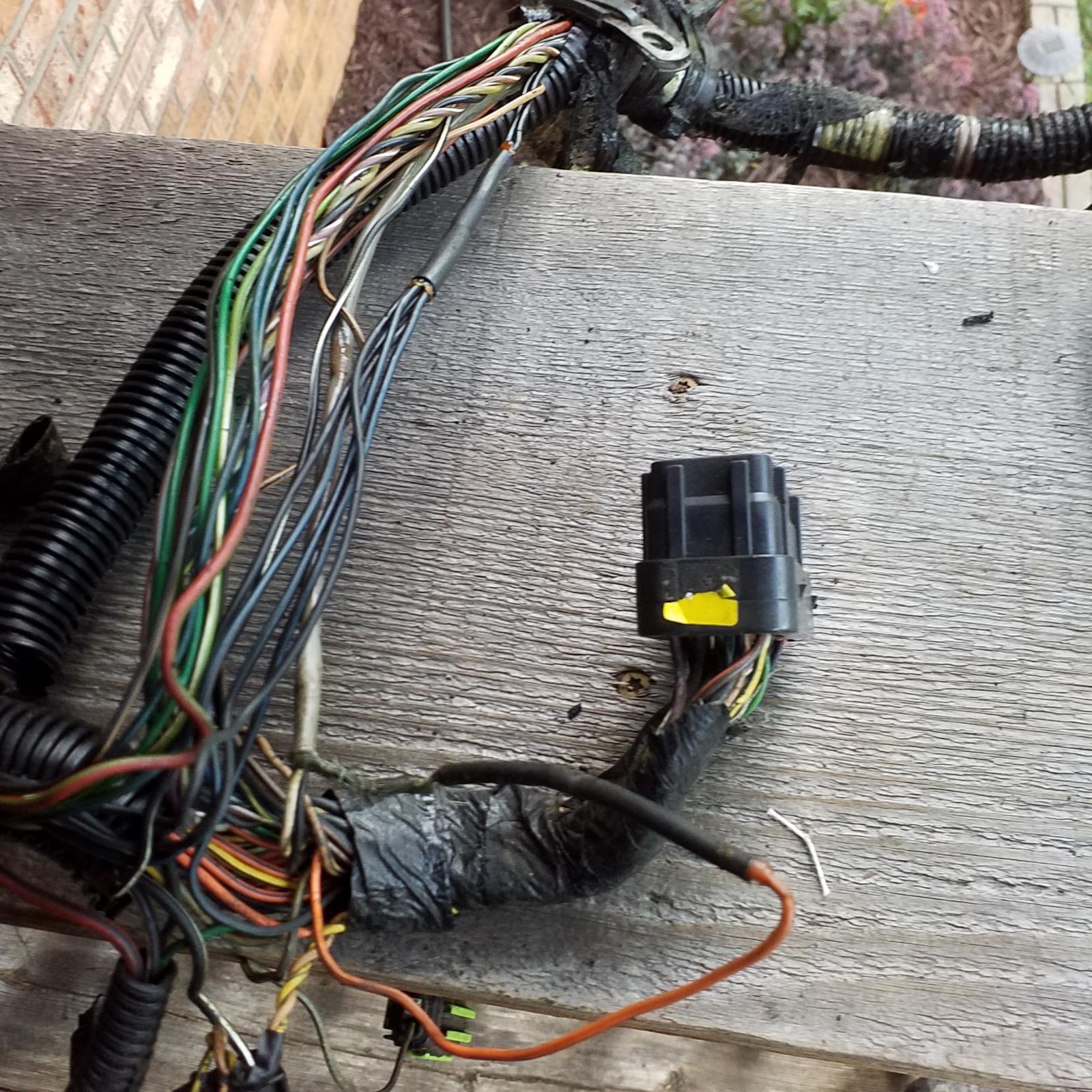
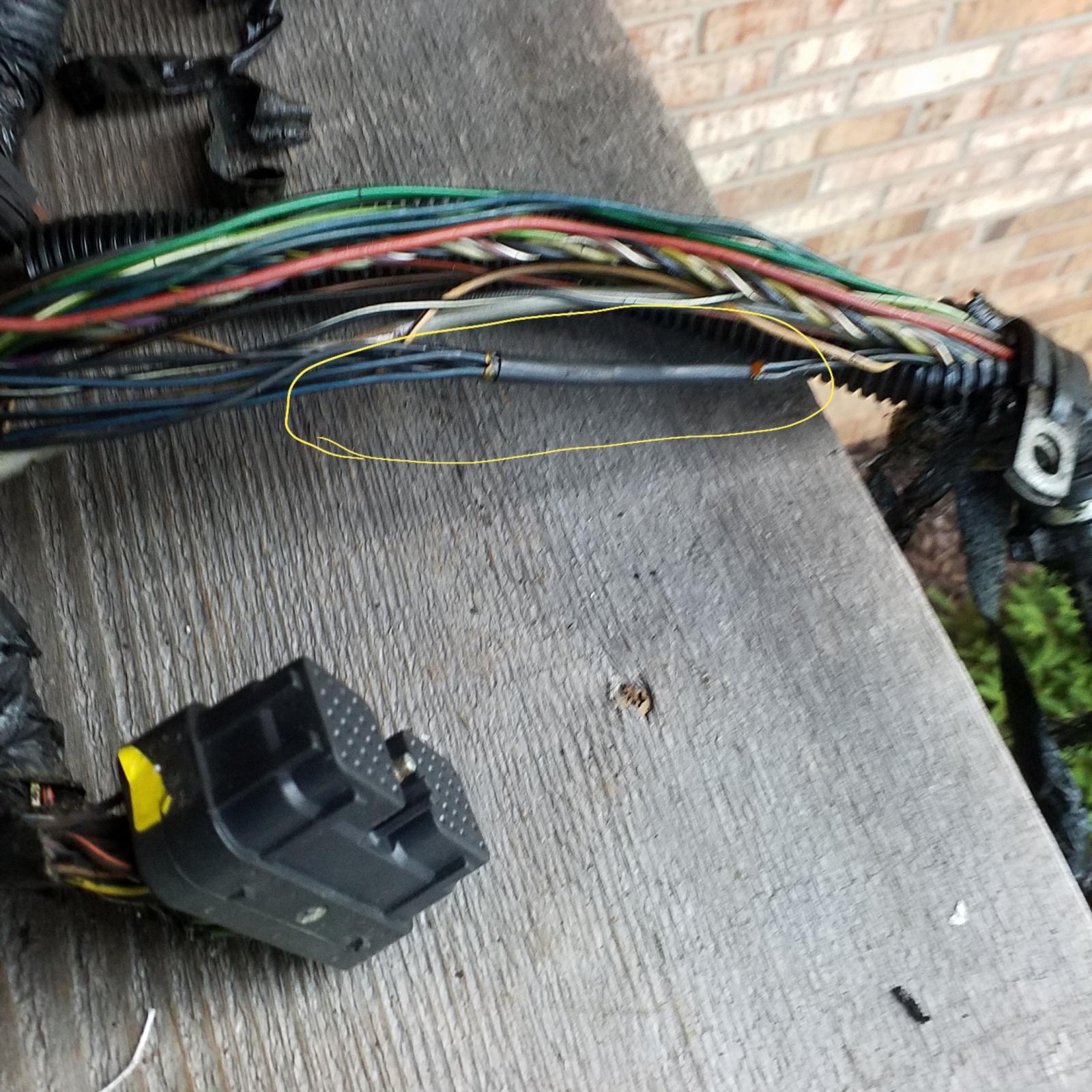
Don't forget the 4 sensor grounds that are not soldered nor crimped together, they are only fused together with some sort of plastic from the factory. :think:. Last time i heard plastic was good for soldering was when this huge 10 foot chicken was at my door.

  • Haha 2
Link to comment
Share on other sites

14 hours ago, JAG1 said:

Don't forget the 4 sensor grounds that are not soldered nor crimped together, they are only fused together with some sort of plastic from the factory. :think:. Last time i heard plastic was good for soldering was when this huge 10 foot chicken was at my door.


Which sensor ground are those? I making a mental list of things I should take care of. That list is getting long. Wiring with OCD can be a time sucker.

I think what I might do it take the OEM block grounds I have in the garage and cut them down and make one ground from the body to block on one side and to the frame on the other, piggybacking to the same mounting bolt as my new battery to block grounds.

Also, I have been rebuilding my G100 ground using a blue seas bus bar. I will make a thread about it in the next couple of days. I found a couple interesting things.

  • Like 1
Link to comment
Share on other sites

  • Owner
On 3/20/2019 at 12:11 AM, JHFIII said:

Lets I add a set of aux lights, or anything really, and I ground the piece to the frame or body. I know there are the two battery to body grounds on the drivers battery


Other solutions for lighting...


Why not go brighter and lower amperage draw. My Morimoto HID headlights are mere 35w and brighter than factory headlights much wider path of light. Then the PIAA LED 530 driving lights are even brighter than my Morimoto HID and draw a mere 15w total. Then my last mod was installing switchback marker bulbs which are seriously bright and draw a mere 3.1 amps. Much more lighting than old school halogen bulbs with much less load on the alternator.


Body grounds are the smaller gauge wires from the body to the battery. I've been looking at it differently by finding ways of improving things but reducing the electrical loads on the alternator. 

Link to comment
Share on other sites

  • Staff

JHFIII, they are as Dripley shows. They are located inside the black plastic conduit going along the front of the engine block and near the front of the VP44 front gear case. I think that's the best way to describe it. 


MoparMan opening up a sunbathing parlor in his garage. :lol:

Edited by JAG1
  • Like 1
  • Haha 1
Link to comment
Share on other sites

7 hours ago, Mopar1973Man said:


Other solutions for lighting...


Why not go brighter and lower amperage draw. My Morimoto HID headlights are mere 35w and brighter than factory headlights much wider path of light. Then the PIAA LED 530 driving lights are even brighter than my Morimoto HID and draw a mere 15w total. Then my last mod was installing switchback marker bulbs which are seriously bright and draw a mere 3.1 amps. Much more lighting than old school halogen bulbs with much less load on the alternator.


Body grounds are the smaller gauge wires from the body to the battery. I've been looking at it differently by finding ways of improving things but reducing the electrical loads on the alternator. 

I read your write up before on that. I really like it.  My truck is a sport model and I impulse bought a set of the hikari LEDs after seeing lot of positive reviews on them when they went on sale on amazon. If they dont pan out, I will do something like you have done. I have an space in my winch bumper for lights, and I recently busted on of my older baja designs HIDs. I am going to replace them with another set of Baja Designs (Im partial to them) LEDs when I get a chance. So point taken on reducing the load. Ive had to fix some stuff wiring wise and I cant resist overbulding the wiring (Plus Ive got a bunch of spare material).

5 hours ago, JAG1 said:

JHFIII, they are as Dripley shows. They are located inside the black plastic conduit going along the front of the engine block and near the front of the VP44 front gear case. I think that's the best way to describe it. 


MoparMan opening up a sunbathing parlor in his garage. :lol:

May as well address those when I do the W/T ground mod. I already had that half done unknowingly because my higher amp alt required a charge wire to the aux and fuse.

Link to comment
Share on other sites

×
×
  • Create New...