

- Replies 38
- Views 6.9k
- Created
- Last Reply
Top Posters In This Topic
-
 Mopar1973Man 14 posts
 -
 JAG1 8 posts
 -
 Me78569 4 posts
 -
 leathermaneod 4 posts
Most Popular Posts
-
I may have another to send in if interested I replaced mine with a used ecm
-
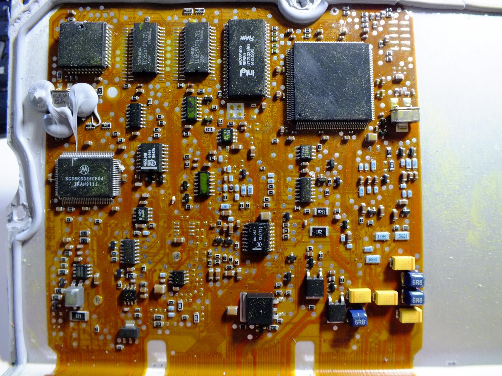
I'm trying to find out some of the chips and other parts within the ECM to learn more about the design. Like the processor has over 72 MB worth of documents on what it can do. I know now that since th
-
Mike, So if the wts issue in the ram? Could we solder on new ram and force a flash by setting coolant and tips to 5v on start.

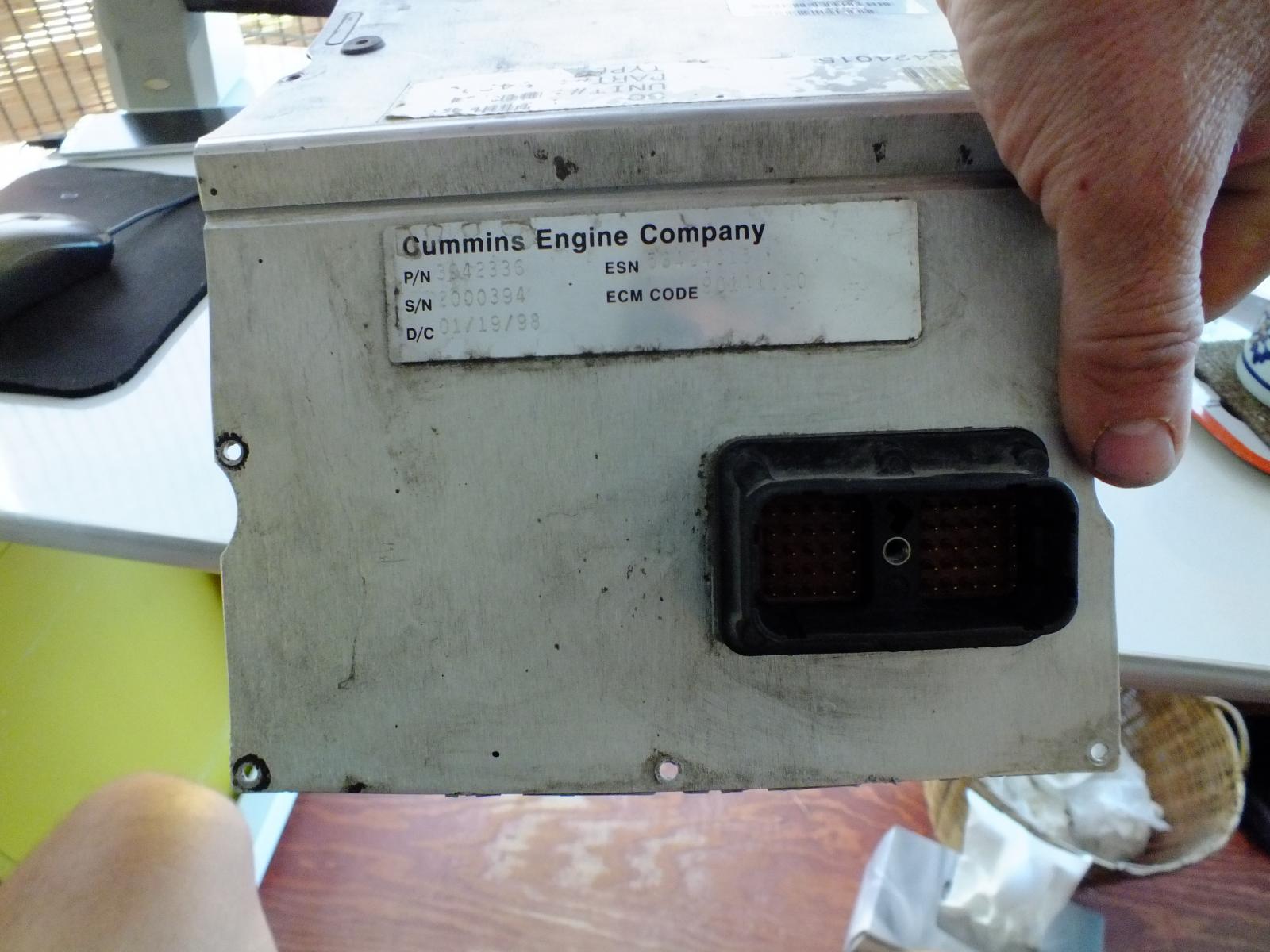
I've got to say Thank You to a member sending my his damaged ECM for study purpose. I know you'll come forward to acknowledge this.
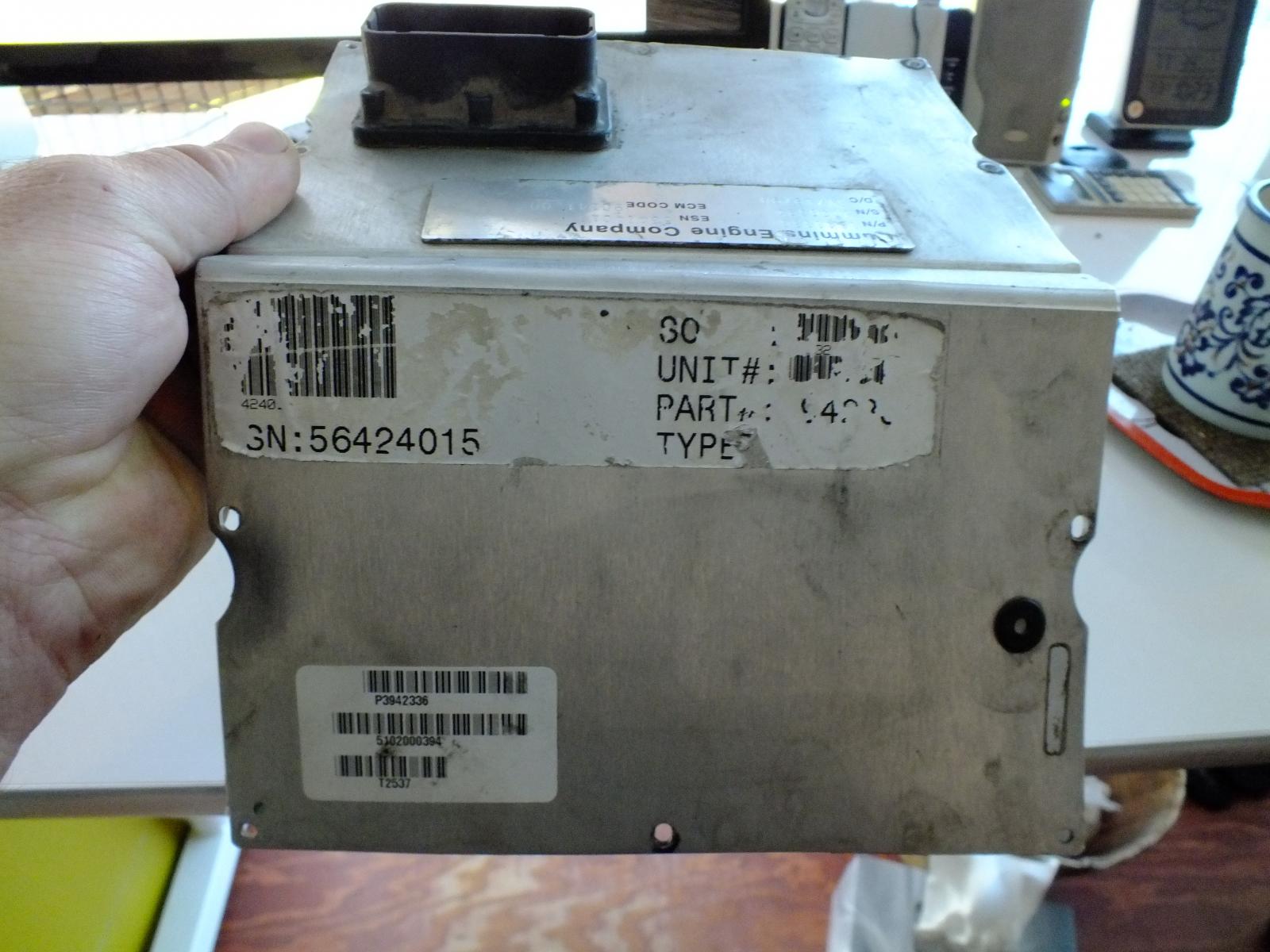
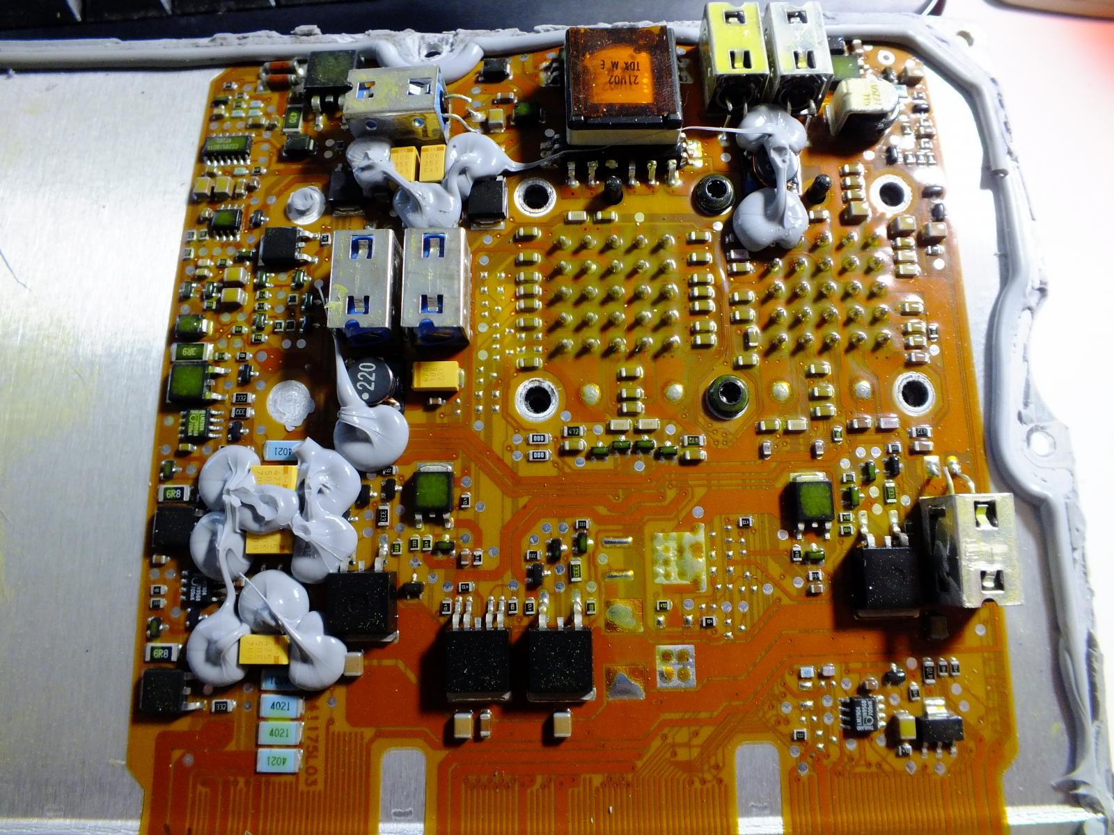
I figured for the sake of knowledge of the ECM why not document as much as I can for other to learn. I can say without a doubt the circuit board is mylar and securely glued to the aluminum case. It's a single sided solder setup but it double sided tracers.
It's going to take me time to hunt down more I've really straining to see the chip numbers through the spray coating on top of them. I'm too afraid to rub it off. Might make things worse.