Mopar1973Man
Owner
-
Joined
-
Last visited
Everything posted by Mopar1973Man
-
Typically even a store would fail above about 1.2 volts AC noise (not really sure). You might have it tested again and see if it passes of fails.
-
I'm sorry to hear about this. After dealing with my own bladder cancer I really do understand what your up against. Good wishes and all I can say is don't give up. Keep a positive thought every day no matter how bad it gets. As long as you keep your focus on getting better it will give you the strength to endure what your starting.
-
Like myself I run level 2 on Quadzilla. More or less its stock fuel with your lead in de-fuel curve. More than enough power for daily driving. If I need a booster shot to pass long truck or series of cars. Yup. I tap the Quadzilla up to level 7 (100% wire tap). Then drop the hammer and let her eat. The level 2 is capped out to 100% fuel that all no added CANBus or wiretap. This allows me to be that sleeper truck... Always a bit of fun...
-
There is a key switch on both sides for arm and disarm.
-
Even with a #5 injector line leaking will make a clutch slip. I'm watching and learning because someday I know I'll find a guy that needs a crank seal next. Matter of fact I should dive into that Ford 7.3L and do a crank seal.
-
Yeah when I burned up the PCM and I stuck the new alternator in of course it wouldn't charge without the +12V to the field. So I drove from Ontario OR to Parma ID to get to friends place for help. About half way there the volt gauge fell to 8 Volts and chime went off and I looked down at the Digital display on my USB charge port and it just fell from 12.00 to 11.99 volts. It will not come back up till the voltage is back above 12.00 again. It a dead clue something is wrong with that fuse/breaker if the CHECK GAGE light comes on and volt gauge is sitting on 8.
-
LOL... No joke I've got Eileen's Son (Jacob) his 7.3L Ford F350 sitting in my yard with one crappy injector. I'm planning on crawling out in the morning and doing passenger head of injectors in the snow storm that is coming. This should be award winning... Then slide indoors and do the power steering pump and pull my steering box and have it looked at by Ryan. Troublesome output shaft seal. So my truck will be down for some time. Then I got Eileen's son which wants to learn diesel so I've been working with him and letting him turn wrench for me. Small bonus nice to have young blood wanting to learn. Me... I never got anything done today but two trips to McCall for parts and meds for the family. Now I'm wore out and just trying to get warmed up again. Hips and lower back are sore now and just time to quit for the day and let my body heal a little bit. I'll admit still later tonight I will fire up the cannabis and relax just a bit. Right now I'm going to work on the web site and fix more tidbit and get it running better.
-
Start out at 13° at 1,500 RPM and step up +4 or +4.5... Your first step up from 15 to 20 is too wide (+5°) even for my truck. 13.0°, 17.0°, 21.0°, 25.0° is +4° 13.0°, 17.5°, 22.0°, 26.5° is +4.5° Starting out above 14° tend to make the bottom end doggy.
-
Me it mostly all long hour standing under two post lift in weird position because I stand taller than lift can lift. If I work from home its lots of kneeling on bumper and laying over the top or laying under. My next project is a power steering pump. Ugh... So my lower back and my hips are always sore.
-
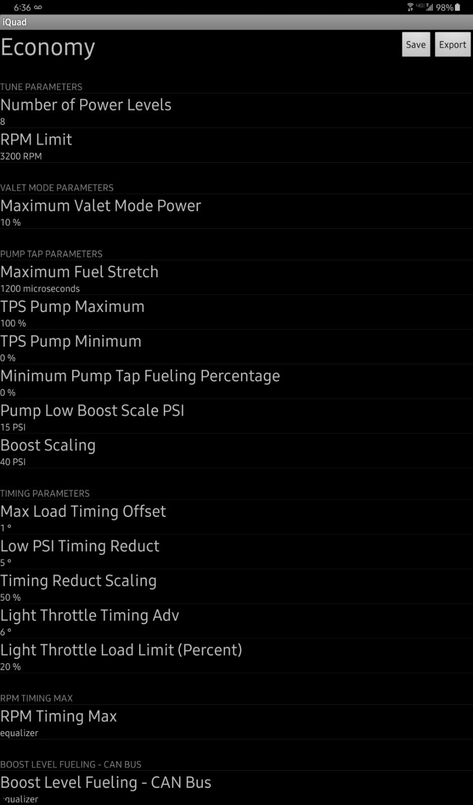
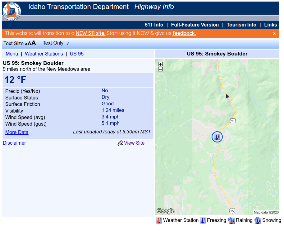
Stock injectors require long duration of being open to make the same amount of fuel. @LorenSYou might want to nudge the cruise timing up some more you notice the engine load may drop a bit more. If you notice the rattle is way more pronounced and then engine load seem to climb a bit your at your limits and need to back down again. Here is my latest Economy tune... Cruise timing at +6°...  I've ran the cruise timing at +4° for the last tank barely made 17 MPG. Now jumped up to +6° cruise timing and now the EGT's dropped really good and the engine oil temp rose about 5° roughly. So now I'm advanced about as far as I want to go. The rattle is more pronounced but EGT's are down, boost is down, and engine oil temp rose slightly. MPG appears to be better now and gaining above 19 MPG rough fuel gauge / odometer math. Here is today's weather...
-
I've had to wait for exhaust system for a local job because of limited material caused from the COVID-19 shut down. I still have issues getting parts in any timely fashion at all. Even just a fan belt for Dodge Dakota took me a full week to get here. Local stores didn't have it.
-
Yeah that is signs of low pop pressure and larger droplets are hard to burn. Takes more time to heat the droplet to vapor, to make it go BANG! Finer mist always will run cooler and smoother. Lower pop pressure enhances fuel flow, Higher pop pressure enhance MPG and clean exhaust, lower EGT's. People tend to forget the pop pressure is the starting point of when it opens period. The maximum pressure of the injection pump is well above 18,000 PSI at WOT....
-
Tip: Thew volt gauge will fall to 8 and set the CHECK GAGE light when the voltage drops from 12.00 to 11.99 volts.
-
I know the feeling to certain degree. Being I've been under a 2 post the weird standing positions you create to reach this bolt or that nuts pays a toll on your body. Time to slow down even more Mike. I know you wired the same way I am we keep working till the job is done but it might come at the cost of your body or health. Just slow down.
-
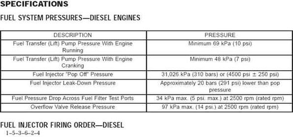
Specification right out of the Dodge FSM... The difference is so minimal... 1 Bar is 14.5 PSI 310 bar = 4496.17 PSI 320 bar = 4641.21 PSI 293 bar is the bottom limit by Dodge FSM (-250 PSI) 300 bar is what builders use (Shorter life span of about 50k to 60K) 305 bar is what builders use (shorter life span of about 70k to 80k ) 310 bar is equal to 4500 PSI - Stock pressure 320 bar is equal to 4641 PSI 327 bar is the upper limit by Dodge FSM (+250 PSI) The only reason builders go low they can hence the flow by going lower in pressure. This makes for a very large droplets and more smoke. Going up makes the atomaztion cleaner and slightly less fuel sprayed. Once you drop below 290 bar the injectors are getting even more smoke. By 280 your start to get a miss at idle. There is nothing gained by low pop pressure injectors but extra smoke and lower MPG's, high EGT's. I towed my RV to Arizona last summer and did over 14.7 MPG on my highest MPG. Averaged 12.6 for the trip to Arizona from Idaho. EGT's would not cross 1,200*F with my cruise set for 65 MPH. 320 bar Injectors are not the cause. The pump goes all the way up to over 18k to 21k roughly in pressure what it can build with WOT. 4 Ways to kill a VP44... Low fuel pressure High AC noise Low Lubricity of fuel Poor fuel filters I've been running 320 bar for 3 years just about now. Over 100k on the VP44 because I didn't tap till after 100k miles. Pop pressure is not the cause... We had people test all the way to 360 bar. Then 330 bar is nearly impossible in subzero to start. 320 bar is clean spray and starts all the way to -40*F which I've tested personally over 3 winters. Remember the Dodge FSM upper limit is 327 bar which I'm still under that limit. Now remember you can lose up to 10 bar in just the break in period of the injectors. Just ask @pepsi71ocean about what the pop pressure was after 28k miles...
-
Wow that's a lot of stuff there...
-
Either way will work just remember to buy a extra fuse to keep in the truck.
-
Down at the wye of the cables you got to have a sharp knife or cutter and cut the friction tape and the cable comes right out. I've done a few of these mods and they ttypically work out good. I've done one in Ontario, OR and it worked out good and finished in just over an hour to do the project. I've done my landlord for my other shop his turned out good but the circuit breaker wouldn't hold his loads for what ever reason. I had to install a fuse on the passenger side and it worked fine.
-
Why? All done for you... I've got my switch hidden in the pouch in the dash. Never know its even there. The bonus to the high idle switch you can do many other task with it. Some of the features and how they help. Cool down a hot cab in the summer. Set for 6 CYL and start the truck with MAX A/C on and it will cool down quickly. Working with a winch you can set 6 CYL mode and keep the alternator charging strong on the batteries while working the winch. Jump start another vehicle. This is so nice hook up and set 6 CYL and let it charge up and start the dead vehicle. 3 CYL mode and exhaust brake I can produce up to 1,000*F EGT's and warm up a cold engine in a mere 8 to 10 minutes from -20*F to 170*F coolant temp. Select the MPG mode and the IAT is forced up to 143*F so the ECM RETARDS the timing in the winter time giving roughly 2 MPG gain. 6 CYL mode is locked as long as the switch is left in the 6 CYL position. If you turn it off after starting you can have it auto cancel at 170*F coolant temp.
-
OEM is a very thin 140 AMP fuse. Same here never popped the factory fuse either. It might be... I'm saying its not possible but at the same time I'm still using a 140 Amp breaker with no problem. Mine is tucked on the BHAF side near the fender and guarded by the heat shield too. If its too close to hot surfaces it could trip early for no good reason.
-
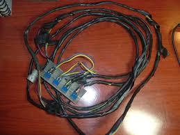
Not to high jack either This is where the concept came from. I figured out how to control the ECM with a few toggle switches and resistors. Same concept today but the package is smaller and much easier to use for you and much easier to produce for me. I've gotta say THANK YOU to @Me78569 being he does my solder work and The Harness Shop in Caldwell, ID that produces the cables. Yup that is VERSION 1.0 back a long time ago...
-
I'm using the cheap China/Amazon breaker. No issues to report. I've done another ground wire mod and even let him use my breaker on the customers truck and would pop the breaker all the time. We swapped to an actual 150 Amp fuse on his truck and the problem left. There is something about system loads or other accessories that keep the alternator constantly charging or weak batteries with internal shorted cells. The break is held to the high charge rate too long and the bi-metal strip heats and pops. My truck I've updated most all the lighting to LED's and HID headlights so my electrical load is very low on the alternator.
-
If enabled... For 6 CYLINDER - IAT must stay below 32*F with grid heaters running, and the ECT must be below 140*F to start. For 3 CYLINDER - IAT must stay below 15*F with grid heaters running, and the ECT must be below 140*F to start. To CANCEL Step on the brake pedal Step on the throttle pedal Auto Transmission shifted into gear. Road speed above 0 MPH
-
It to have the ground on the driver side battery and the charge lead on the passenger battery totally separated and now less like to bleed the AC noise over. When you unwrap the charge lead you find its wrapped right with the ground wire.
-
Did anyone run a Smarty on the truck possibly? A Smarty Tuner will automatically enable the high idle and leave it for you too. This is how I got mine enabled on my truck and remians enabled.