


Mopar1973Man
Owner
-
Joined
-
Last visited
Everything posted by Mopar1973Man
-
There is no ground terminal in the PDC. Both of the studs are +12V from the battery. The black cable is the charge lead from the alternator. The actual PDC ground is on the front driver side fender near the headlight.
-
Like I just sold a EFI tuner to a local gent here for 2012 Ram 6.7L he's not tech savvy nor does he own a computer. Not many up here want to tune their truck.
-
Not have the pleasure of playing with a full programmable tuner. I've used EFI Live tuners. But these are preprogrammed. Never found anyone wanting a true programmable tuner up here.
-
I've heard of that but never seen it done as of yet.
-
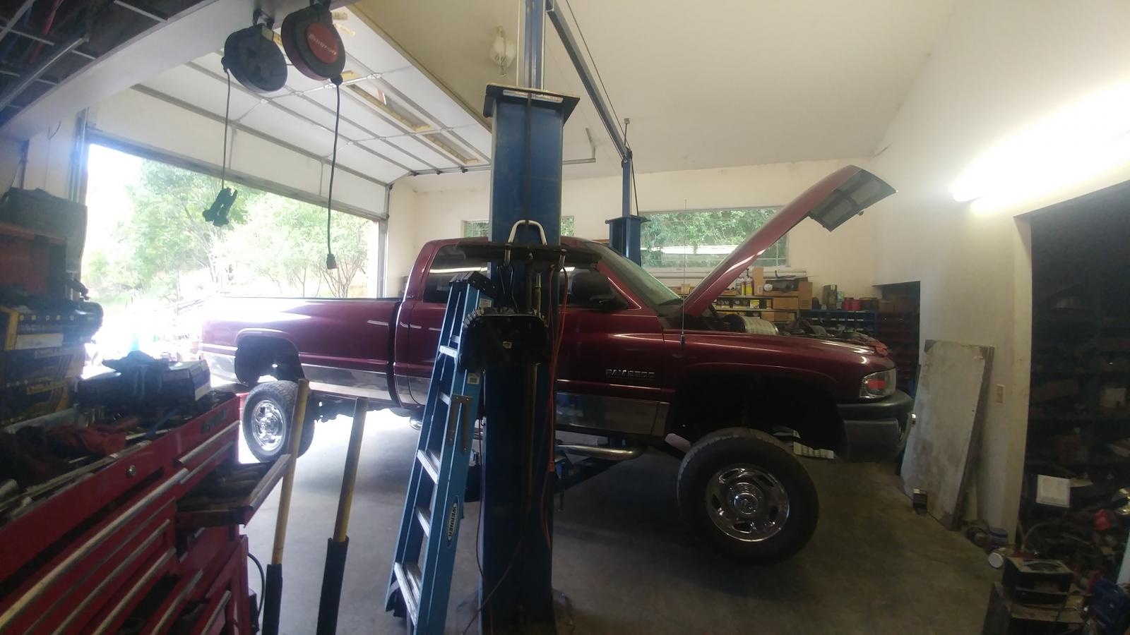
I gotta admit it was nice to head down to the shop and stuff my beast on the lift and do an oil change, adjust my parking brake, rotate the tires, and lube the rest of the steering and driveline. I was able to bust it out super fast compare to at home. Grabbing jack stands, jack up the front axle, set the stands, then jack up the rear axle set the stands. Still laying on the floor to do an oil change and grease the rest. Sure finding out fast I've got muscles I've not used in awhile being now I'm standing most of the time and my poor head is getting beat up. I gotta remember to look up before walking under or duck and keep my head down till cleared. Still gotta... Flush the brake system Flush the power steering system Flush the cooling system Install a new thermostat Install a new fan belt
-
As far as I know all tuner only affect the engine. They do not have the capacity to alter transmission shifting. Typically tuner will change the amount of throttle required to keep moving. This in turn changes the throttle valve position on the transmission and changes how the transmission shift. At least for the old 98.5 to 02 Dodge's the PCM controls the transmission. Now on the 2005+ truck the ECM and PCM have merged together. Still in all I don't know of any programmer that can affect transmission performance.
-
Look at it this way... The minimum oil pressure is 10 PSI at idle and 30 PSI at 2,000 RPM. How long would you expect an engine to last with oil pressure dipping down close to the minimum values? Now VP44 is cooled and lubed with only fuel. The overflow vale is only open at 14 PSI and up. Now if your pulling a grade and the pressure is dipping to 10 to 12 PSI would be like engine oil pressure dropping to 25 to 27 PSI at 2,000 RPM. It might not fail today but it does add up to extra wear on the VP44.
-
Could you post a picture of these ports? Could be a few other things.
-
No. Here is the causes of the Bus Failure... he CCD data bus can be monitored using the DRBIII scan tool. However, it is possible for the data bus to pass all tests since the voltage parameters will be in “range“ and false signals are being sent. There are essentially 12 “hard failures“ that can occur with the CCD data bus: Bus Shorted to Battery Bus Shorted to 5 Volts Bus Shorted to Ground Bus (+) Shorted to Bus (–) Bus (–) and Bus (+) Open Bus (+) Open Bus (–) Open No Bus Bias Bus Bias Level Too High Bus Bias Level Too Low No Bus Termination Not Receiving Bus Messages Correctly Again you need to check the BUS+ and BUS- voltages and you should have 2.49 volts and 2.51 volts at rest after booting up and engine not running. Red probe on the Pin 11 of the OBDII port and Pin 3. The black probe goes to ground on the DVM.
-
Go back over the CCD network wiring. Check for the 2.49 and the 2.51 volts on the bus.
-
As you see this isn't my first rodeo. I was turning wrenches since 1984. I started working on the parents cars before I even had a drivers license. Have been since. Now in the Diesel realm and can't seem to stop. I love the challenges and learning as I go along. I've made my fair share of mistakes and screw ups. I have always made things right again. I have been to the school of hard knocks. Like this afternoon I'm in Ontario taking care of the dialysis treatments for Mom. In the mean time I'm re-working the Paypal account to handle the invoicing in the future. I'll have WiFi internet and 3G Cell signal (network extender). I won't be limited to cash only for very long. I'll be able to process Credit / Debit Cards for the shop too. Like talking to Mom this morning I realize I've got a ton of work to do to get this rolling smoothly. Shop is a mess, Front area needs cleaning up, I've even got an office too that is stacked with parts. The only thing I'm lacking in is TIME...
-
Actually, Mon, Wed, Fri... Then from 8am to about 5pm ill be at the shop. Tue, thurs, and Sat still making my trip to Ontario taking care of Moms dialysis treatments. Basically leaves me with Sun off for my own thing. I've been working from home for about 13 years. Been doing mobile A/C service for better than 7 years. Then been doing all the repairs for the fire dept since 2004 when I joined.
-
Been turning wrenches for quite awhile, I've worked for other shops for quite awhile, now its my own show, I get to pick what I want to do. Lots to be done yet. Now I've got a place with a 2 post, lots of tools, and other equipment like fork lift, hotsy (hot water power washer), etc.
-
Good deal. I had to do the same when the alternator shorted out the PCM it burned the circuit board bad. Yeah the price on the reman PCM it pretty steep but its a complete unit all programmed and ready to go. Make sure to fix the problem before installing the new unit.
-
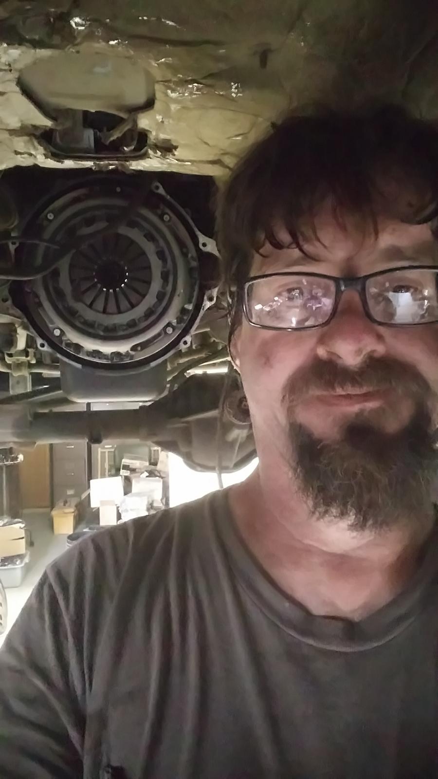
I'm not afraid to work from the ground. I'm going to get the shop owner get the other 2 bays cleared out. Like after completing the dual disc clutch yesterday. Needless to say that Valair drives super nice for a dual clutch. My next job was doing front brakes on a 2001 Dodge 3500. It had a camper in the bed so I just pull the nose up in the shop and worked from the floor. Come to find out that truck has been to the salt flats too many times. Need slide pins for the calipers which are on order. Then capped out my day with changing a lift pump on a 1992 Dodge 250. Crazy part is the jobs are stacking up quickly and seem as soon as I clear my to do list for the day the next work day is already filled up.
-
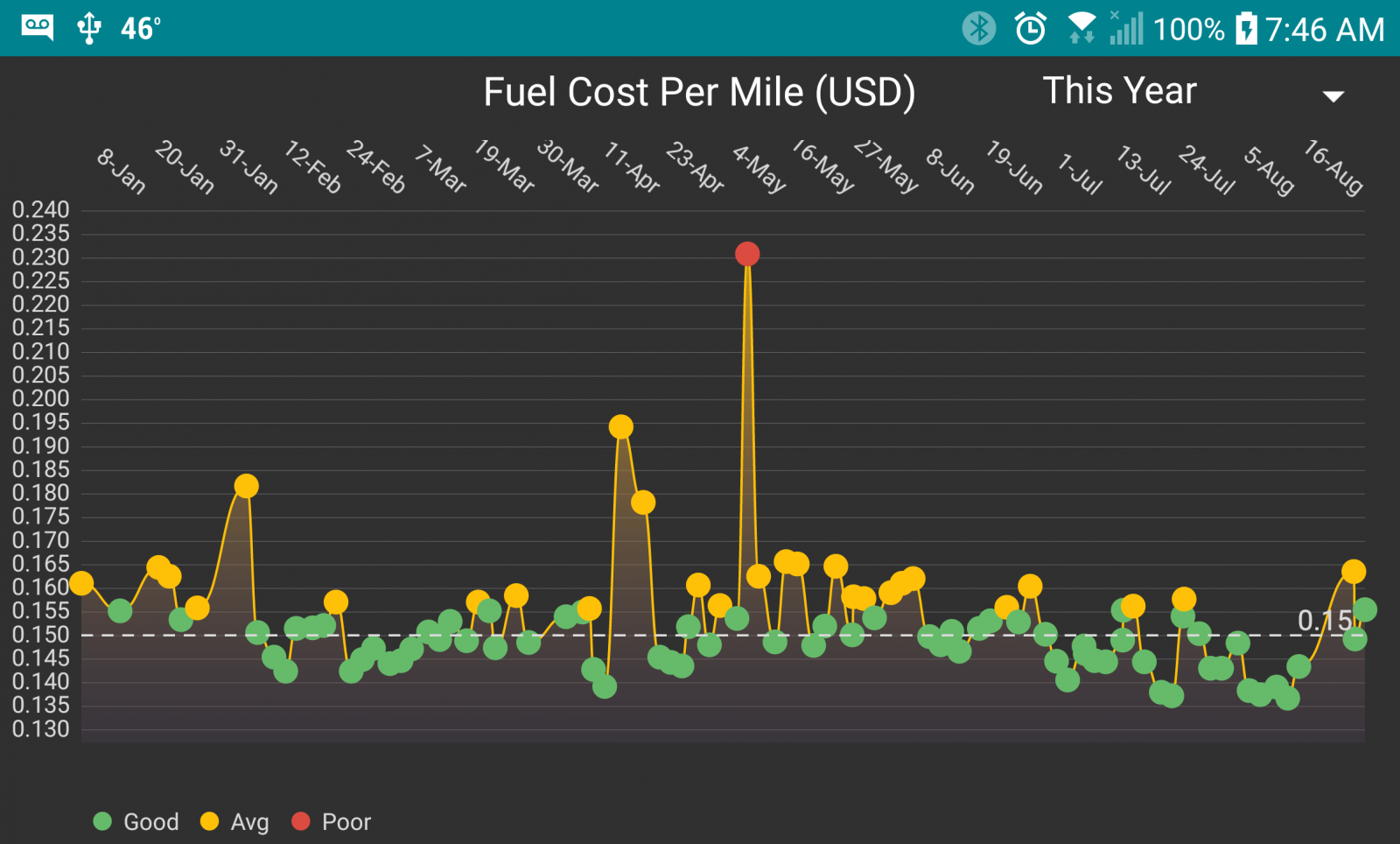
It was a lightning strike that started a tree on fire. The crew at the time didn't handle the start of this properly. Then USFS continue to play "Back Fire Bob" games and continue to lose more and more ground. These kind of fires can be stopped fast and easy but USFS doesn't make any money unless the fire burns. This means the fire has to be big and nasty and deplete the fund for the area then USFS and ask for more crews, equipment, etc. If they stomped out the fires quick the Gov't won't give any aid or funds. So for all those carbon taxes. Really? When USFS is a "Fire Manager" they do not put fires out they manage them till the end of season snows put them out. As for myself I'm a Fire Fighter I put the fire out right now. No questions asked. Like the current fire just east of me is a bit over 2,000 acres and still burning. USFS is having fun milking the system. Yup. Idaho power already informed me that they are nearly 100% tapped out for power production during the summer and hard winters. Last thing we need is thousands of people plugging in there cars and creating brown outs. Not to mention wait till people weigh in on price per kilowatt and cost per mile vs diesel cost per mile. I'm sure you not going to get the same numbers but if the cargo and weight was equal I'm sure the diesel will win hands down. Currently $2.799 a gallon for diesel, about 15 cents per mile for the year so far. Including towing trailers, hauling heavy cargo, stop and go traffic, and 80 MPH runs on interstate. Traveling roughly 1,000 miles a week for MoparMom's dialysis treatments and for work. Then what I spend per month in just fuel.
-
The new 027 Revision pumps no longer have a diaphragm in the pump just a steel disc now.
-
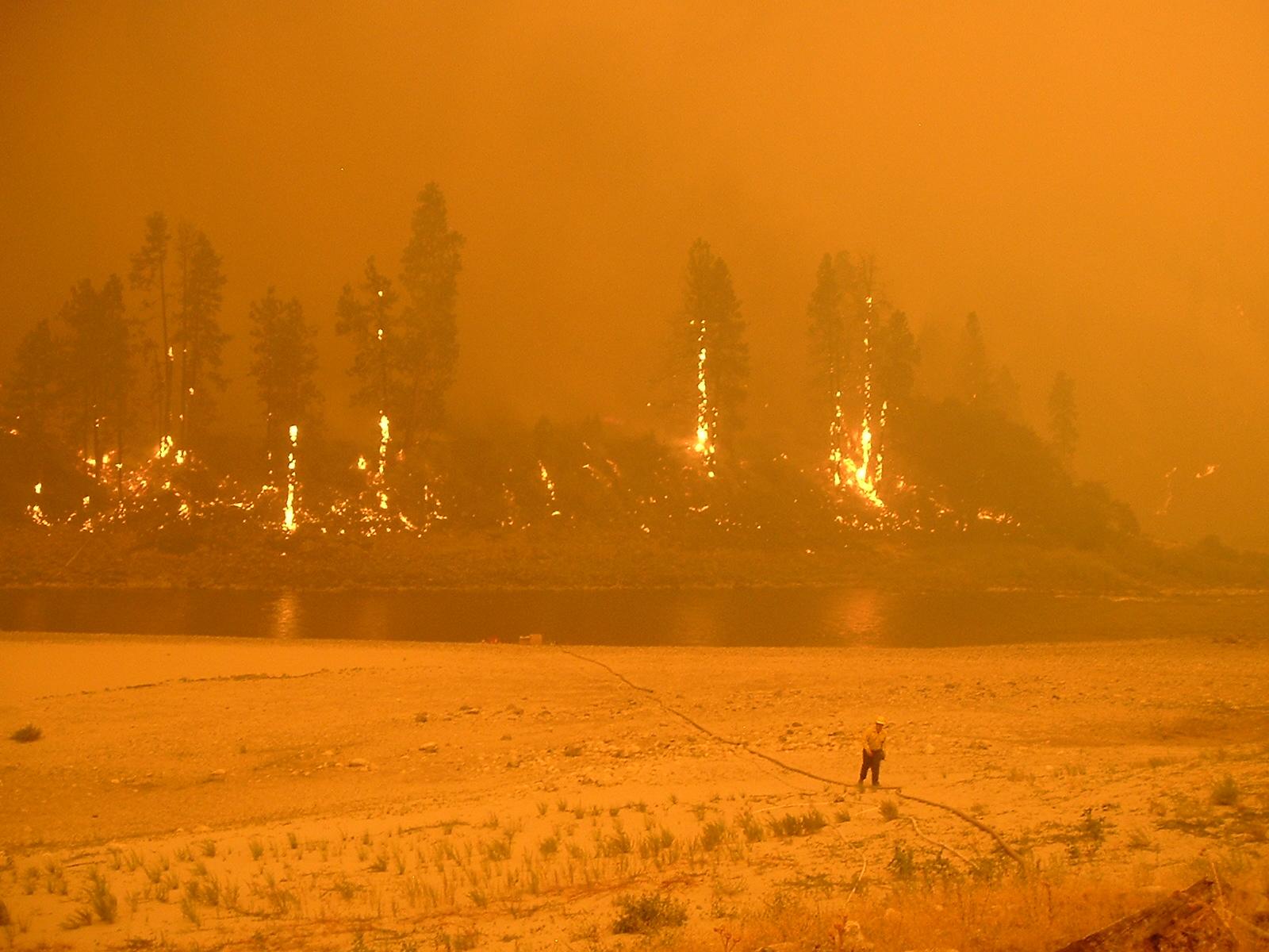
How about the forest fires that emit more CO2 than my pickup will in entire life in a mere hour. This is NOT photoshopped. This is noon on the Salmon River, during the Teepee Spring Fire. This orange haze is the smoke and CO2 produced by this fire burning in the Nez Perce National Forest. A light aircraft is nothing, our trucks are nothing, This fire alone produced more pollution in one hour than all of California could in one day. I'm the camera man and Station captain on the scene of our group. The gent in the photo is one of our crew I sent down to start the pump keep water flowing during the event.
-
Actually I've seen both happen. It is possible to blow the front seal and then some cases i possible to have hard starts because the timing is over advanced. There is a few members here that filled the crankcase full of fuel from a blow front seal. Then hard starts than require pulling the lift pump power.
-
Your still welcomed to hang out and ask questions on the Ford forums here. I'll try and help with what I know. Got some knowledge of Ford stuff too.
-
So far I've had zero issues with my ISSPro EV2 gauge or pressure sensor. Very good gauge as long as the pressure sensor is NOT at the tap point. I've got the 5 foot of air brake line from the snubber then the sensor.
-
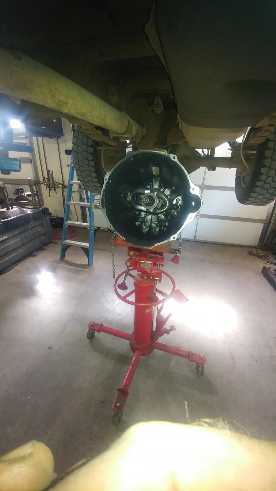
It was nice for once to work standing up and no laying on my shop floor on creeper. Then even better yet when 5pm rolls around to just turn off the lights and lock the doors. My work stays at work now. I'll admit that it took me quite a while to get the transmission stabbed yesterday. Then Valair kept me guessing with the change up of American bolts that are 12 sided in the pressure plate thinking most modern stuff is metric. Duh moment...
-
First project my single to dual disc clutch. 2012 Ram 6.7L.
-
Get a set of 7 x 0.010 @ 320 bar injectors you can have natural lope. Mine is mild, only shows as you coast to a stop. Pretty impressive in traffic. Still it idle smooth at at full stop.
-
Just had one yesterday that wanted a A/C leak fixed in less than 2 hours and have no freon supply being Riggins was closed already. I've gotta travel today. Sorry you thought about your A/C the evening before his trip to Utah. Oh well... I'm not going to kill myself because of your poor planning.


