


Tractorman
Yearly Subscription
-
Joined
-
Last visited
Everything posted by Tractorman
-
I have had Bilsteins 4600's for about 130,000 miles now (since 2015). They have worked out fine for me. The truck rides and handles good. I have heard that the 5100's are stiffer than the 4100's. You did not mention which shocks you have. - John
-
My brother-in-law moved his 2003 2500 4wd NV5600 truck yesterday. While he was moving it, I noticed a ticking sound coming from under the hood. Upon investigation we found the whole clutch fan assembly laying in the bottom of the radiator shroud. Not what I expected. The unit had unscrewed itself from the threaded pulley hub. The interesting part is that there is hardly any damage. The large clutch fan nut shows witness marks where the outside of the crank pulley was rubbing and two fan blades show similar wear from rubbing on the crank pulley hub. The fan blades never contacted the radiator or anything else (including the fan clutch thermal switch and wiring harness), which was amazing. So, I am thinking that maybe the fan clutch was locked and the assembly came off when the engine was shut off; otherwise, I think the damage would have been much more severe. Anybody ever had this happen to them? We replaced the fan hub bearing in December, 2018, just over 20,000 miles ago. I used the proper wrenches to remove and reinstall the fan clutch. Most of my life I was a mechanic by trade and I have been around Dodge trucks and many other similarly equipped vehicles and I have never witnessed or heard of this happening. A new Mopar fan clutch and a new Dorman fan have been ordered. - John I just realized I posted in the wrong forum. Should be in the third generation powertrain forum. Maybe someone could move this post. Thank you, - John
-
Thank you @W-T! That was the best compliment I could have ever received! - John
-
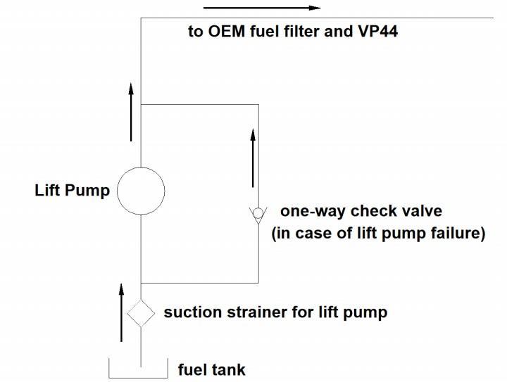
Lift Pump Bypass for VP44 Trucks? The Modification – This subject matter might be a bit controversial, but I believe I have found a good solution regarding driving a VP44 equipped truck when a lift pump has failed while on the road. After I did an experiment for checking fuel return volume from the VP44 fuel injection pump on my truck, I realized that I came upon what I believe to be a simple solution to one of the biggest fears for VP44 truck owners - a lift pump failure while on a road trip. For the experiment I routed a fuel line with a one-way check valve around the lift pump so fuel would still flow when the lift pump was non-operational (simulating an electric lift pump failure). The reason I say “fuel would still flow” is because the VP44’s internal vane pump will draw the fuel into the VP44 injection pump. This lift pump bypass circuit includes a one-way check valve to flow fuel in a direction from the fuel tank to the stock filter housing. This lift pump bypass circuit on my truck is now a permanent circuit. Below is a diagram of the circuit. The Experiment - I arrived at a conclusion after experimenting with fuel return flow volume with or without an operational lift pump. The results of the experiment showed that fuel return volume did not change for either lift pump condition. Each test from the experiment showed averaged return fuel flows at approximately 19 gallons per hour, whether the lift pump was operating or not operating. The conclusion - My conclusion is that the lift pump only provides a positive pressure to the VP44 injection pump. It is the VP44 internal vane pump that takes over from here and supplies the fuel flow and operating pressure for all of the VP44’s internal components, including injector flow and fuel return flow for cooling. It is not just this experiment alone that helps me draw this conclusion. After much research over many years regarding the VP44 injection pump operation, and reading many posts from people who have done VP44 return flow volume testing with a flow meter, I am confident in my belief that the lift pump’s only job is to supply a positive pressure to the inlet of the VP44. The lift pump accomplishes this by providing more flow that the VP44’s internal vane pump can consume at any time. The VP44’s internal vane pump takes over from this point and provides flow and pressure to cover the needs for VP44 pump operation and cooling, which includes fuel flowing over the 14 psi overflow valve. The Test Drive - I test drove my truck for over 25 miles without the lift pump operating. My low pressure fuel indicator lamp remained on during the test drive. The truck drove fine. I shut the engine off and restarted it several different times. I applied wide open throttle several times. There were no performance issues during the test drive. If the lift pump failed on my truck on a road trip, I would not hesitate to continue driving the truck with this lift pump bypass circuit in operation. This simple fuel supply modification will allow a truck to continue to be driven with a lift pump failure. The VP44 internal vane pump will continue to supply fuel to the VP44 injection pump via the lift pump bypass circuit and will also continue to supply ample return fuel flow to the fuel tank for cooling the VP44. This modification could be a practical solution for those who drive trucks with a stock engine mounted or frame mounted lift pump. An in-tank lift pump bypass circuit would be more difficult to build, but would be doable. Lift Pump Bypass Operation - During normal lift pump operation, the one-way check valve will not allow fuel to return to the suction side of the lift pump. A fuel pressure gauge at the inlet of the VP44 pump will always register a positive pressure. With a lift pump failure, the fuel will pass through the free flow direction of the one-way check valve directing fuel around the lift pump into the VP44 pump inlet via the stock fuel filter housing. A fuel pressure gauge at the inlet of the VP44 pump will register zero at this time. There will actually be a small vacuum generated as the internal vane pump will be drawing fuel from the tank through the suction screen and fuel filter. What is important to note is that the same volume of fuel will be flowing through the VP44 injection pump and returning to the fuel tank as when the lift pump was operating. I am not recommending or suggesting that anyone perform this modification to their truck. However; personally, I am very confident that this modification will cause no harm to the VP44 injection pump should a lift pump failure occur. In fact, I believe the bypass circuit offers more protection to the VP44 pump than a circuit without the bypass feature simply because a failed lift pump could block or severely restrict the fuel supply circuit. I am posting this information on this particular site because, in my opinion, this site provides the best and most accurate information when it comes to second generation Dodge Cummins trucks, especially VP44 trucks. I say this with one exception – and that exception is: I don’t think this site has provided the best information on how the lift pump operates in conjunction with the internal vane pump inside the VP44 injection pump and how the 14 psi overflow inside of the VP44 injection pump interacts with the internal vane pump. I do think that members of this site go to a lot of effort to provide very useful information to solve problems for owners of Cummins equipped Dodge trucks and I am thankful for that. Any questions or comments will be appreciated. - John
-
@pwcracer, thank you for letting the forum know the cause of your problem. Your documentation once again shows the value of performing a voltage drop test. A ground connection that appears to be good visually and is tight mechanically does not necessarily mean that the connection is good enough to handle the electrical current passing through the connection.. For anyone interested, @Mopar1973Manhas written an article about the benefits of voltage drop testing and how to perform the test. One of the best things about performing this test is that the test is performed BEFORE disturbing the electrical connection in question. The results of voltage drop testing are always accurate. - John
-
Are you saying that an idling engine dies when you turn on the headlights? Even if the grid heaters are activated when the headlights are turned on, the engine still should not die. Can you be more specific about the symptoms your truck is having? Such as: How long has this problem been occurring? Does it occur every time? Did the problem start occurring just after any other repairs were done? What is indicating that the grid heater are on? Is the engine warm or cold when this happens? Etc. - John
-
Before pursuing any further, I would check all grounds for continuity. Any single poor ground at the right ground connection could give you the symptoms you are describing. Poor grounds are notorious for leading one astray when using a multimeter or a test light. Poor grounds back feed voltage to unrelated circuits. Since you have a monthly subscription, I think you have access to wiring diagrams here. There is also a wiring modification called the WT Wiring Mod (or something like that) available on this site . This mod deals mostly with ground wiring. It is an important modification to do for the 24 valve trucks. - John
-
Your symptoms do suggest that there is a problem with the valve spool in the steering gear box. A steering system flush may help if some debris is causing the problem. Did the problem begin occurring with the replacement of the power steering pump? A little more detail may help. - John
-
I agree with greatly increasing caster. I did this 10 years and almost 200,000 miles ago. After the adjustment I had the caster angle checked - it was 4.5° positive. This modification is the single most steering improvement I have done on my truck. I once considered replacing my steering with the T type, but after changing the caster angle and replacing the track bar with a Rare Parts track bar, I changed my mind. The truck steers well and I have never experienced the "death wobble" (currently 359,000 miles on the truck). @Haggar, did you mean "since camber is not adjustable"? - John
-
Since you have the valve cover off, I would check the operation of each intake and exhaust valve as well as the operation of each push rod just to make sure there is not something else wrong there that could give the same symptoms as a bad injector. - John
-
What I have always looked for when looking for engine performance in a vehicle is, "what will be the engine rpm in a specific gear at a specific highway speed that I would drive at based on a specific engine (gas or diesel). Engine performance charts are the place to get this information. At minimum, I would want to know at what engine rpm is peak torque and peak horsepower. Engines typically perform best just above their peak torque rpm, or at least around their peak torque rpm. For example, my stock '02 Cummins is 245 hp and 505 lb/ft of torque. The horsepower rating is at 2900 rpm and the peak torque rating is at 1600 rpm. This is why engine rpm's between 1800 and 2000 work well with @Mopar1973Man's final drive ratio recommendation. A '99 Ram 5.2 gas engine specs are 235 hp and 300 lb/ft torque. But the horsepower rating is at 4400 rpm and the peak torque rating is at 3200 rpm.. In general, this would tell me that a rear axle ratio of 4.10::1 would be more suitable because of the peak torque rpm. Knowing every gear ratio for the transmission and tire diameter will be key for getting this right. - John
-
I have not experienced death wobble myself. From many articles I have read, it seems that there is a consensus that it is not likely that any one worn steering or suspension component would trigger a death wobble. However, with many slightly worn components, the sum of all the worn components could trigger a death wobble. Also, larger tires and wheels can play a role. - John
-
I would at least do a visual check sighting down the side of the truck from the front right corner and then from the front left corner to see if the axle is centered under the truck. If appears to be okay, then I would re-center the steering wheel. After re-centering the steering wheel, I would turn the steering wheel from center all the way right and then left to see if the number of turns are equal in both directions. If they are equal, the sector shaft in the steering gear box is centered as it should be and all is well. If the number of turns are significantly different, there is a problem somewhere in the steering or suspension system that needs to be addressed. - John
-
I have more questions than answers. Are you the original owner of the truck? Were any of the replacement track bars adjustable? Has anyone ever re-centered the steering wheel during life of the truck? Is the truck lifted? If everything is still stock (including replacement track bars) and no steering or suspension parts are bent or damaged in some way, I think it would be okay to re-center the steering wheel using the adjustable sleeve near the pitman arm. - John
-
It may help to pinpoint the noise source by trying this road test: * Lock out the overdrive and accelerate the truck to 2000 rpm in third gear. Take your foot off of the throttle and observe the noise. * Lock the transmission into second gear and repeat the test. * Lock the transmission into first gear and repeat the test. Does the whirring noise sound about the same in each test? If it does, then it would seem that road speed is not relevant. This would rule out things like driveshaft, transfer case and differential. When I have difficult problems to diagnose, I try to be very specific with my methods of testing and reporting the results. You have mentioned that the noise is heard when decelerating, but you did not say a specific rpm when the deceleration starts or a specific rpm when the noise quits. Specific detail from you may help pinpoint the cause of the whirring noise you are experiencing. - John
-
I am fairly certain it is a remanufactured pump. My VP44 was replaced at 87,000 miles under warranty in August, 2005 - 0216 code and you could hear that it had a timing issue. The code was actually being set one year and 20,000 miles earlier in August, 2004, but I continued driving the truck. I learned how to drive around the limp mode. When the warranty work was completed, I was bummed that I got a remanufactured VP44 - not a new one. But, after lots of research, I learned that Bosch had several problems with their VP44 injection pumps, such as rotors that didn't get deburred, timing pistons/ cylinders that were made from inferior materials, PSG's that had solder issues, a plastic diaphragm to absorb pulsations, etc. Bosch addressed these issues, but did not mention the details to the general public. After learning all of this, I changed my mind and I am very happy that I got a remanufactured VP44. I currently have just over 270,000 miles on my replacement VP44. So, by the time we got our 2002 trucks, I think the remanufacturing process was beginning to take care of all the afore-mentioned problems. - John
-
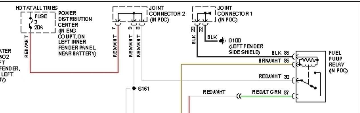
Here is a diagram of the fuel pump relay circuit. Note that there is a joint connector in the PDC in the grounding circuit. - John
-
I am assuming this is a relay for the fuel transfer pump. This relay should get its power to the coil portion of the relay from the ECM - yellow/whit wire that used to be directly wired to the fuel transfer pump. A fused circuit from the battery should go to the load portion of the relay. This relay should power only the fuel transfer pump. Since you have identified a red/green wire on this relay, I believe you are talking about the fuel pump relay in the power distribution panel. This relay supplies power to the VP44 only. The power to the coil portion of the relay comes from the ECM - a brown/white wire. The ground for the coil is a black wire and is grounded on the left inner fender area. This ground is important. Fuse #3 (20 amp) in the power distribution panel supplies power to the load portion of the relay via a red/white wire. Can you confirm what I have written? - John
-
No worries. There will be embarrassment for a very brief moment and then you will forget that it ever happened. - John
-
I think everybody missed the fact that you have a two wheel drive even though it is shown in your signature, I know I did. Otherwise, I would have mentioned that you could have inspected and adjusted the wheel bearings if they were in good condition. - John
-
Me neither... - John
-
It is beyond my ability to comprehend as to why a simple brake light switch would be engineered in such a manner that it could not be reused. i suppose if you removed your brake pedal, you couldn't use that again either. - John
-
About 150,000 miles ago my brake lights were staying on. I removed the brake light switch and modified it to be reusable. I cannot remember what I did to it, but I know it was simple. I am currently using the original switch now with over 350,000 miles on it. - John
-
May not be related to what is going on now, but a melted fuse holder is a sure indicator of a poor connection inside the fuse holder. The heat generated from the resistance of the poor connection (voltage drop) melts the fuse holder. Definitely worth checking out and maybe worth performing a voltage drop test at that location. - John
-
I think the changes were made for safety. On higher speed limit two lane highways, a vehicle signaling for a left turn from the highway is easily recognized by on coming traffic when the vehicle making the left turn has turn signals that switch off the driving lights and only operate the turn signal. From what I have read, earlier versions allowed the driving lights to remain on when operating the turn signal. This made the turn signal more difficult to see for oncoming traffic and sometime contributed to collisions. I use Daniel Stern's turn signal driving light module to make the turn signals be driving lights when the headlights are not being used. The module is designed to give the driver the choice of leaving the opposite driving light on when using the turn signal or turning off the opposite driving light when using the turn signal. I have mine set up to turn of the the opposite driving light. As soon as the park light or headlights are turned on, the driving lights stop operating. - John


