


Tractorman
Yearly Subscription
-
Joined
-
Last visited
Everything posted by Tractorman
-
Don't forget to check for excessively worn shock absorbers. They may not leak and may appear to be normal, but if one or both of them collapse or extend easily without resistance, that can definitely contribute to your condition. The only way to check the shock absorber's condition is to disconnect the shock absorber at one end and operate it by hand. There should be lots of resistance, especially while extending. Death wobble is usually generated by several worn steering / suspension parts and having large tires and wheels on the truck. What is your tire size? - John
-
The title says, "2001 3500 EX Cab Dually 2WD?" with a question mark. Is this a two wheel drive or a four wheel drive truck? If it is a two wheel drive truck, then it is has an independent front suspension - no track bar. But it does have upper and lower ball joints and it does have upper and lower control arms. Are any of these loose? Are you truly experiencing the death wobble? If you are, you probably think that your truck will leave the road and you won't live to tell about it. I didn't think that two wheel drive trucks had a problem with the death wobble. - John
-
Actually, the most important benefit of an exhaust brake hasn't been mentioned - it is its ability to use the engine to hold back a heavy load on a long steep downgrade without the use of service brakes, or at least with very minimal use of the service brakes. If an emergency stop is required half way down the grade, you will have cool, fully functioning service brakes available that have not been overheated from controlling vehicle speed while going down the grade. To me, that alone is worth the 1000 or so dollars - the saving of wear and tear on pads and rotors is just a bonus. - John
-
I don't think it is clear in @Mopar1973Man's post as to whether or not he re-used the injectors or he installed new ones, but I am sure we will find out. - John
-
@Mopar1973Man, in the last few days I have noticed that there are no longer any names associated with "Likes" for my posts and others that I see. For example, I have two "Likes" in my previous post, but I don't know who they are. Anyone else experiencing this problem? - John
-
What is that red wire that has a messy connection to the alternator output terminal? If there are more wiring connections on your truck that are done in that manner, I would be thoroughly looking over the electrical system. - John
-
Did you find the cause of the 4th gear failure? How did it fail? Just curious. - John
-
I can't speak for others, but I have 312,000 miles on the original six speed transmission with no repairs. I replaced the clutch with an OEM clutch at 297,000 miles (failed pilot bearing). I use the exhaust brake on my truck in the exact manner that @Mopar1973Man describes. - John
-
Not surprising. - John
-
Moving the lower control arm forward will increase positive caster. This will utilize the weight of the truck to improve the handling of the truck for straight line driving and to improve returning the steering wheel to center after cornering - the positive. It will also add more steering effort (especially sharp turns) and put a bit more load on the power steering and steering gearbox under certain conditions - the negative. Personally, I have set mine to 4 1/2 degrees positive caster years ago and I like it - I think it is well worth the trade off. - John
-
What ? Are you saying my truck's retarded? (attempt at humor). I understand what you are saying about the limitations of the Smarty S03. On a different subject, is the screenshot in your photo the actual display you are looking at while driving down the road? If so, what is the size of the screen? - John
-
@Evan, it is good that you have read @pepsi71ocean's Smarty S03 article. Another good read, if you haven't already done so, is @Tittle Diesel Performance's posts regarding what a Smart S03 representative told him. Two important items: 1. He lists the default Revo settings (torque management, timing, and fuel duration) for each software setting (SW1 through SW9). This makes for a good reference point when deciding which Revo settings you want to change, which direction you want to go, and which settings you will leave default. 2. If all Revo settings are left to default, the software in general increases torque, advances timing, and increases fuel duration progressively from SW1 through SW9. But, if you select a Revo number in either Torque Management, Timing, or Duration that is not Default (0), then those parameters stay the same regardless of software number (SW1 through SW9). My truck has a manual 6 speed transmission and the engine has RV275 injectors, so tuning for me is much more simplified and using the information from @Tittle Diesel Performance's posts, the software settings I have tried seem to agree with that information - at least for my truck. I believe @pepsi71ocean has had a different experience. Your truck seems to be a closer match to @pepsi71ocean's truck. It seems that with automatic transmissions and large injectors, the transmission shift points can be greatly affected with different Smarty settings which masks what is really going on at a particular setting. This would definitely make it harder to tune the truck. These are only observations from my point of view from reading different posts, as I have never tried to tune a truck with an automatic transmission. - John
-
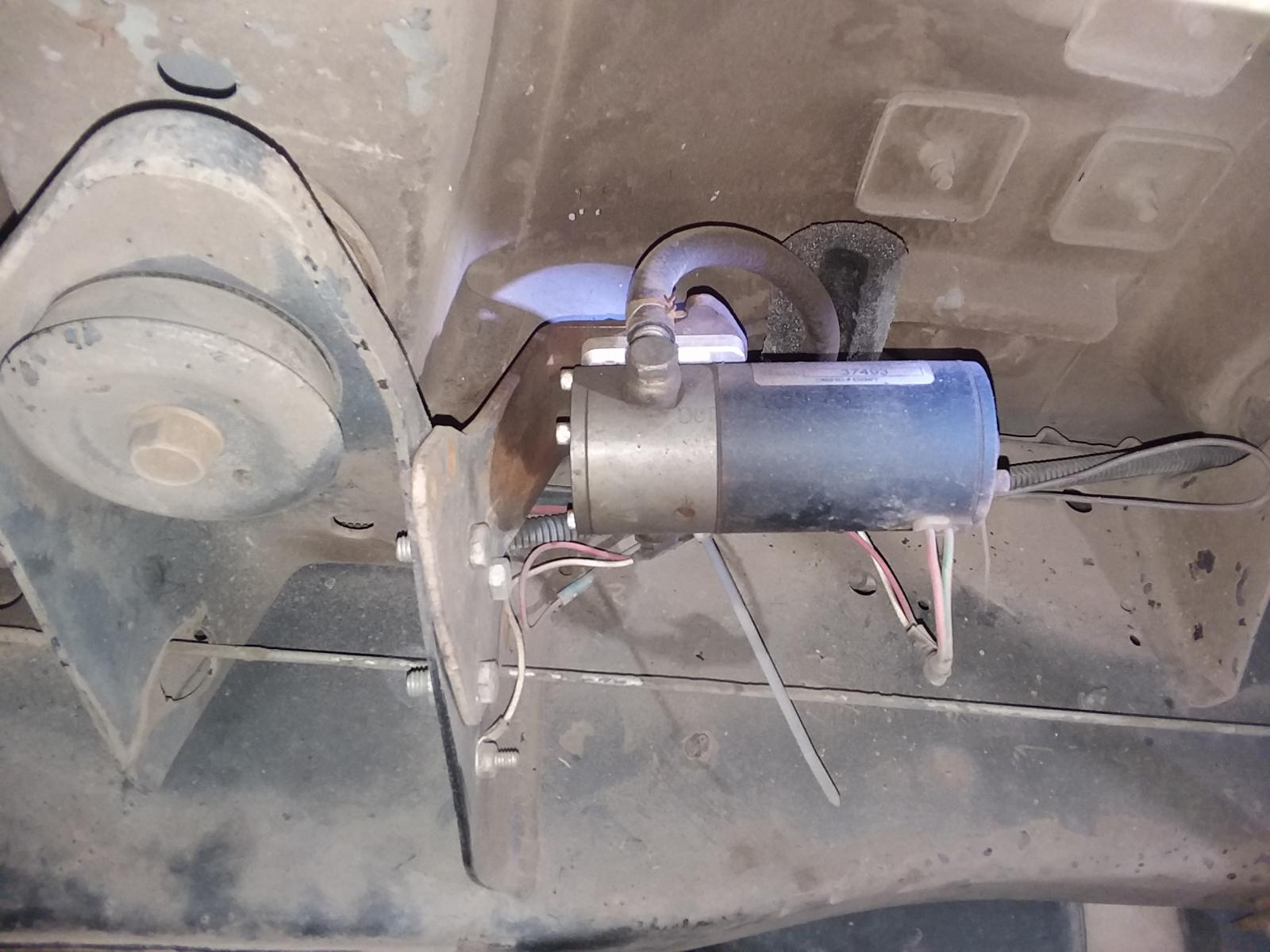
A few years ago I bought a used FASS lift pump and mounted it onto one of the rear cab mounts right at the front of the fuel tank. I just stayed with the factory lines and it was easy to tap into the fuel lines on the inside of the frame. I also installed an in-line fuel strainer (Napa 3270) on the inside of the frame between the tank and the lift pump. - John
-
@dripley, I checked where the power for the lift pump relay contacts come from on my truck. As you suggested, it comes from the battery connection at the PDC. A short distance away is a 15 amp in-line fuse. @Daleb, I can't remember if you mentioned where your lift pump gets its power, so if you haven't checked, it would be a good thing to verify. If the power for the lift pump is tapped into an existing circuit, the additional lift pump current could easily overload that circuit. Ideally, the lift pump should be fused and relayed from the PDC and the coil portion of the relay triggered by the ECM. - John
-
Since you said that you just purchased this truck, do you know any history about the truck - particularly the headlight system. * Are the headlights still OEM? * Is there one 9004 bulb for each side? (one bulb per side system) * Is it a sport headlight system? (t2 bulbs per side system - 9007 bulbs for 2 outside lamps and 9004 bulbs for 2 inside lamps) * Does the truck have fog lights? If anyone has modified the headlight system, I would start my troubleshooting there. - John
-
@dripley, when my first VP44 failed 64,000 miles and was replaced at 87,000 miles, it was replaced under warranty along with the lift pump and the associated wiring. At that time the factory fix was to install an in-tank lift pump and to relay that lift pump. The coil portion of the new relay was triggered by the ECM, but I don't know where the power source comes from for the relay portion that actually operates the lift pump. I was wondering if you might know. I think I might have to do some investigating - John
-
If the headlight wiring is OEM with a factory one bulb per side system, then all of the headlight controls (headlight switch and dimmer switch) use the ground wiring side of the bulbs to switch the headlights on and off. The headlights are fed by a hot lead. Does your truck have fog lights? I am assuming your headlights were working normally before your problems with Joint Connector #2. Try the following: * Leave the key switch off and operate the headlight switch. The low beams and high beams should operate normally. If they don't, operate normally, then I would start my troubleshooting here. * If the headlights do operate normally with key switch off, then I would be looking for something powered by the ignition switch circuit that is switching the ground side wiring for the headlights to ground. Sometimes when I am troubleshooting electrical problems I like to prove what is working correctly rather than trying to come to a conclusion that I can't prove. For me, it is a process of elimination. - John
-
Good thinkin'! - John
-
The two times over the life of my truck that I noticed the breather tube was messier and leaked more oil than normal, I had a vacuum leak. Neither time was the vacuum leak large enough to noticeably affect vacuum operated controls, but the excessive air flow showed up through the breather and added to the mess. Each time I repaired the vacuum leak the breather began venting normally again. - John
-
I use the treated wipes the guy hands me at the car wash for interior cleaning. They are white so I can see when I wipe off a dirty spot on the engine. - John
-
If I understand correctly, that junction connecter supports a few fused circuits and some other circuits. I don't see anything stopping one from bypassing just one damaged circuit and leaving the rest intact, just as long as the new circuit has the proper size fuse and wire gauge. - John
-
I figured you did know that, just thought it worth a mention. I am glad that the miss was something simple - you probably had all sorts of things going through your head on that test drive, and none of them good. When I was in my late twenties, I owned a mobile auto repair business for a few years and many times I found myself working in less than desirable weather conditions; so I hope you are feeling good about what you have accomplished working in the elements under the canopy. - John
-
The pushrod absolutely needs to be straight, as it rotates constantly while in operation to ensure uniform wear on its mating surfaces on both ends. - John
-
Sounds like there might be a trend here - thanks for the heads up... - John
-
It doesn't sound like the intake valves were held open - that's good. Were you able to rotate the afflicted pushrod to see if it is still straight? If the pushrod is straight I think you are good to go. The raw fuel symptom makes sense - no fresh air entering the combustion chamber. - John


