


Tractorman
Yearly Subscription
-
Joined
-
Last visited
Everything posted by Tractorman
-
Since the headlights are relayed, I am guessing that your truck may not have the trailer tow package which would relay the taillights and clearance lights for the camper. If the headlight switch is handling the combined load of the truck's and camper's tail and clearance lights, the switch would get hot. Just a guess. My truck has the trailer tow package and the headlight switch never gets hot, in fact it is still the original headlight switch. I relayed the old headlights immediately when the truck was new just to have better lighting and to take the load off of the headlight switch. - John
-
I am assuming that your 02 truck has OEM sport headlights. Aren't they relayed? - John
-
The opening for the headlight housing in 2001 truck should be large enough to accommodate a sport headlight housing without any modifications. If you haven't done so already, be sure to relay the new headlights because the length of the OEM wiring is so long and so undersized that it is one of the main reasons the OEM headlights perform poorly. I have had an after-market sport headlight conversion for about 2 1/2 years and although there is room for improvement, they perform far better than the OEM single bulb headlights. - John
-
Just wanted to follow up on this topic. I was able to use a Smarty Touch programmer to read actual fuel rail pressure and the truck owner purchased the block-off tool. With all six injector fuel lines connected, the rail pressure maintained about 900 psi while cranking. With cylinder #1 injector line removed and rail plugged, fuel pressure immediately responded to above 5,000 psi and engine started and continued running on the five remaining cylinders. Fuel pressure remained steady at just above 6,000 psi at idle and responded as commanded under acceleration. Engine oil and filter have been changed twice since fuel dilution problem. Number one cylinder injector has been replaced with a new Bosch injector and the truck is running normal with normal rail pressure readings. A lengthy test drive was performed and power is normal and smooth. There appears to be no smoke or engine blow-by or unusual engine noises. The truck owner will monitor the engine oil for fuel dilution, oil consumption, blow-by, and performance for the next few weeks. If all is well, he will be installing five more new Bosch injectors. I thank all for your assistance and I especially thank @AH64ID and @04Mach1 for their very specific advice that led to a productive conclusion. - John
-
VP44 vs. HPCR!
-
It took me to 250,000 miles to get a Smarty S03, then 303,000 miles to upgrade from stock injectors. So maybe I am headed that way, but at the rate I am going I should die before I am "sick". - John
-
My speed varied a lot. Maximum was 65 mph, but mostly 60 mph where there was no snow pack on the road. About 250 miles of driving was on snow pack - 30 to 50 mph. Overall, I am very happy with the RV275's performance. - John
-
In this particular case I think all of his alternators would have bench tested fine. He needs to know why they aren't working on his truck. That is why I would go to the extent of making a separate field control circuit. - John
-
@mbloom65, I would be looking for something that might have happened when you changed out the original alternator, since it was working fine. Something as simple as a poor ground like @JAG1 suggests or something else that is being overlooked could cause the problems you are experiencing. If the truck were mine I think I would rig up a complete separate temporary circuit with either a fixed resister or a variable resistor and 5 amp fuse protection to the field control circuit of the alternator. This way I could prove whether or not the alternator is working properly without risk of damaging the PCM. - John
-
They are a definite improvement. I do have to keep in mind that I am comparing the OEM injectors with 305,000 miles on them to new Bosch RV275 injectors. Just having new injectors will improve performance. I had to dial the fuel back considerably on the Smarty S03 and I advanced the timing a step, but the engine now pulls very strong starting from 1300 rpm's and up - great for a manual transmission. Smoke is much easier to control. I netted 20.7 mpg on an 800 mile round trip to Baker City and back, which I think is good for winter time driving. - John
-
When I read your original post, I am assuming the first alternator you removed was still working because you said, "replaced my alternator in preparation for getting my ECM rebuild". You didn't say, "replaced my alternator because it wasn't working". It would be valuable information for the readers to know whether or not your original alternator was still working. - John
-
Your article is very much appreciated. I have never understood why there is so little operational information given by the manufacturer. I have always liked the Smarty S03 because I tow a fair amount. For me, you have shown that different SW settings can significantly change how fast the TPS signal ramps up with the same foot pedal effort. I don't think I would have ever figured that out. Just that one piece of information alone should help a lot of people get their trucks tuned better - I know it has made a big difference for me. Thank you, - John
-
Good observation. These are the kinds of things we will have to watch for as our trucks get older. - John
-
The noise you have described with an idling engine and transmission in neutral is a normal sound for a dual disc clutch and a warmed up transmission. The pulses from an idling long stroke diesel engine are transmitted through the heavier mass of the dual discs, intermediate plate, and pressure plate causing gear rattle in the transmission. It is that rattle you are hearing, not the clutch assembly. When you depress the clutch pedal, the rotating mass comes to a stop - quiet! When you select a gear and engage the clutch - again, quiet, because the gears are now loaded and gear train slack is removed. - John
-
This is good advice in general, but keep in mind if one is not very knowledgeable regarding drum brake operation and the parts are installed incorrectly from a previous repair, one may duplicate those errors and continue to have braking problems. A photo of the correct rear drum brake assembly from a repair manual can be very informative. - John
-
The power brake portion of the brake system is powered by the power steering pump with an accumulator, not a vacuum boost diaphragm. - John
-
The power steering pump supplies power steering fluid to operate the brake booster. There is an accumulator on the brake booster that stores power steering fluid under pressure for power brake applications. If you haven't done so already, with the engine off press and hold the brake pedal briefly to drain all of the power steering fluid from the accumulator. Do this several time to ensure the accumulator has discharged all of its fluid. There is a possibility that air could be trapped in the accumulator from when you did the brake booster replacement. - John
-
We're waiting...
-
. I bypassed the transfer case vacuum switch and plugged off the ports. I installed the new vacuum switch in the cab. If my truck is stopped I can engage either the transfer case or the CAD first for 4 Lo or 4 Hi. If I want to shift to 4 Hi on the fly, I slow the truck to around 20 mph and shift the transfer case first because it has a synchronizer that absorbs the energy to bring the front driveshaft up to speed. Once the front drive shaft is up to speed, I then lock the CAD. I also leave the CAD locked and just use the transfer case to go in and out of four wheel drive as needed. - John
-
The option "shift on the fly" is advertised with or without CAD (center axle disconnect). You will need to look at the axle to see if there is a CAD unit attached. If you do not have the CAD - end of conversation. If you do have the CAD, my preference for control would be the vacuum switch. The one disadvantage of the mechanical cable setup shows itself when you attempt to engage or disengage the CAD and the axle splines are not lined up when engaging, or if there is torque being applied to the axle when disengaging. One hand will always be dedicated to having to push or pull the cable control until engagement or disengagement occurs. Sometimes that can be annoying. With a vacuum switch control, you just flip the switch and the vacuum motor does the rest when the axle splines are lined up or when axle torque is removed. I didn't buy a kit - I just used a $2.00 vacuum controlled HVAC switch from a GM vehicle in a salvage yard. It has worked fine for over 300,000 miles. Which ever way you go, you will like it. - John
-
I did know that SW1 is the fuel saver program and I did know that it has aggressive timing, but like you say - how much is unknown. I used SW1 just for a reference point and since my truck was empty, I knew couldn't hurt anything. I thought it was interesting that the SW3 performed just as well as the SW1 as far as fuel economy taking into consideration the elevation differences and that I was doing a lot of mountain driving. Also, I just realized today that I need to adjust my fuel economy recordings that I reported in the earlier post. I had set the Smarty to stock briefly before my trip so I could see the difference between my old stock injectors and the new RV275's. I forgot to reset the Smarty to adjust for the 245 tires again. I wrote in a previous post that I traveled 889 miles, used 41.4 gallons and netted 21.47 mpg. Not true... darn!, I adjusted the miles driven (reduced by 3.5%), so I really traveled 858 miles, used 41.4 gallons netting 20.72 mpg. Still a good number. I will edit my previous post to reflect the correction. Well, I guess I can't edit the previous post. Hopefully, people will read far enough down to see the correction. Again, thanks for your input. - John
-
I would put them on a slow charge for several hours (a 10 amp battery charger will do) . When batteries are pulled down to nothing, it takes a long time to get a full charge. Heavily discharged batteries have a fairly slow absorption rate, so no matter how much power you throw at them, they can only absorb so much energy in a certain amount of time. Battery condition also plays a role. - John
-
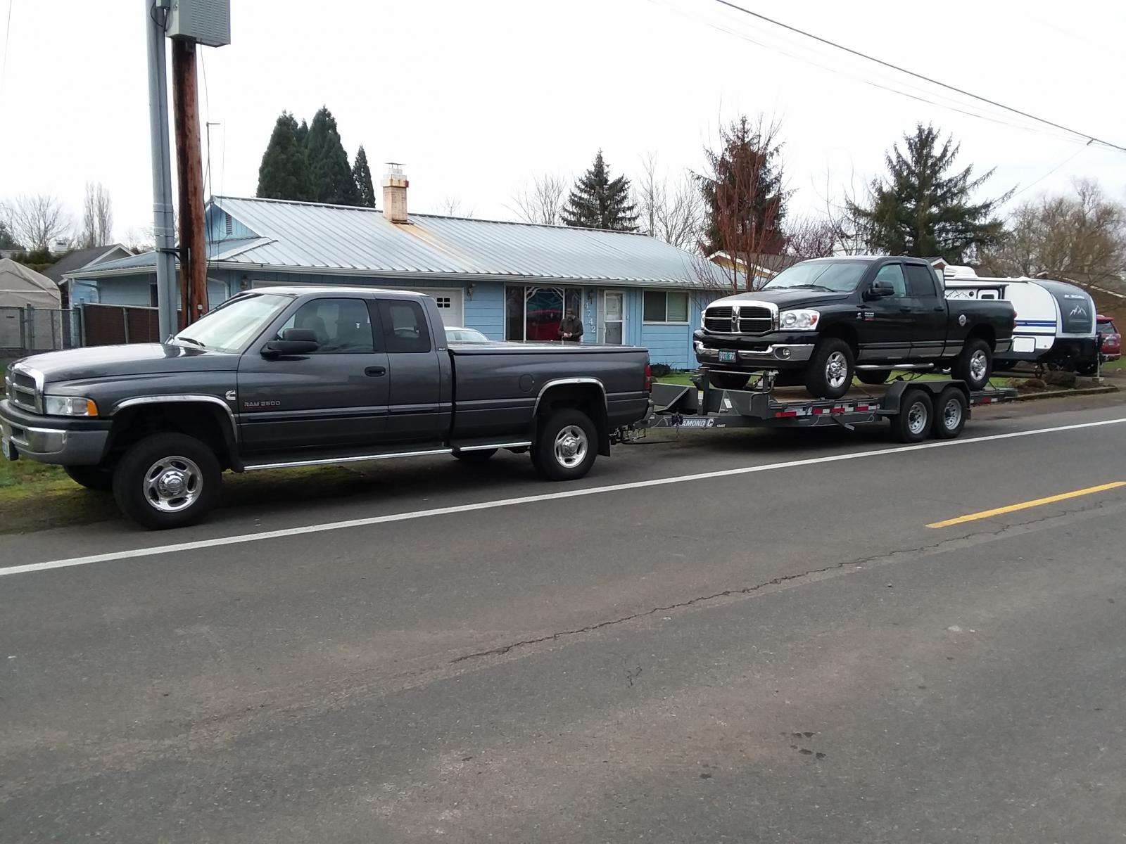
I am back home from the round trip to Baker City and back to Scotts Mills (near Salem). The truck weighed in at 8,100 lbs. I set the Smarty to the fuel economy program SW1 TM-6, T-default, D-default at the beginning of the trip. The tank was filled with B5 fuel and the first fuel stop was in John Day. The route used was Hwy 22 over Santiam Pass, through Sisters, then Hwy 26 through Prineville, John Day and onto Baker City. I spent three days driving around Baker City. Most of the 85 miles of highway between John Day and Baker City was snow packed. Also, three other passes west of John Day were snow packed. The first fuel stop was John Day (336 miles, 15.3 gallons netting 21.96 mpg with B5 fuel). I filled the tank with B20 fuel. The next fuel stop was John Day again (John Day to Baker City and back to John Day) (252 miles, 12.9 gallons, netting 19.53 mpg with B20 fuel). I filled the tank again with B20 fuel and I changed the Smarty settings to SW3 TM-6, T-3, D-2. The last fuel stop was at home. (301 miles, 13.2 gallons, netting 22.80 mpg with B20 fuel). There were several variables involved with this trip (two different Smarty settings, B20 and B5 fuel, snow packed roads, new RV275 injectors, 3,000 feet elevation change to and from, etc.), so I cannot say specifically what played into the miles per gallon recorded. Overall, I was pleased with the performance and fuel economy. Total: 889 miles, 41.4 gallons, averaging 21.47 mpg. The power was very good with both Smarty settings. The first setting (SW1 TM-6, T-default, D-default) had some timing rattle and throttle at low rpm’s surged a little. The second setting (SW3 TM-6, T-3, D-2) had less timing rattle and smoother throttle response at low rpm’s. It was easy to control smoke accelerating from low rpm’s, even at higher elevations with both Smarty settings. I attribute this to the new injectors. @pepsi71ocean, my original Smarty setting before I started my trip was SW3 TM-6, T-2, D-2. So, at John Day on my return trip I used that setting but bumped the timing from 2 to 3 as you recommended. I couldn't say that the turbo spooled differently, but the performance was good and still pulls hard down low and the timing rattle was not annoying. I think I will drive with this setting for awhile and then try the SW5 settings that you recommended. Thanks for your input. Also, the 245/75R16 tires performed well in the snow. Had to slip in a picture of the truck on at the property where we will be building near Baker City. - John

-
My decision was influenced by the Big Three in 1987. Ford and GM thought it was a good idea to put naturally aspirated V8 diesel engines in front of three and four speed transmissions in their pickup trucks in the early 80's. Let's see - crazily run up the engine rpm's to handle the few gears, pour out back smoke (especially at higher altitudes), and enjoy all the noise without getting the power or fuel economy of a diesel. I give credit to Dodge for not joining the foolishness. I really wanted a diesel engine because I knew what they were capable of. I was frustrated that there was not an in-line four or six cylinder turbocharged diesel engine available in a pickup by 1987 - it's not like it was rocket science. So, in 1987, when I found out that Cummins was offering a 50 state emission certified turbocharged 4 cylinder diesel engine (4BTA3.9) that was already made to fit in any Dodge, Ford, or GM pickup with a small block engine configuration, I ordered one. I ran that engine in two different 1/2 ton vehicles totaling just under 300,000 trouble free miles. At the time there was nothing like driving up Vail Pass in Colorado at 65 mph in overdrive with no smoke. If anyone would have known that they were just passed by a 3.9 liter four cylinder diesel engine, they would have just shook their head. When the time came, it was a no-brainer to buy my 2002 Dodge Cummins which I will continue to drive for years to come. - John
-
If I am driving on a 50 mph road such as you have described, my truck will always stay in 6th gear, even when I am towing. If I can easily accelerate (which I can), I see no reason to run a lower gear (with lots of engine noise) for such a light engine load. Remember, peak torque for a stock engine with the NV5600 is 505 lb/ft at 1600 rpm. I think that would leave you with an over abundance of torque to motor down a flat road in sixth gear at 50 mph. Just another opinion. - John


