


Tractorman
Yearly Subscription
-
Joined
-
Last visited
-
That will be quite the project. Just curious, what are you going to do with the front suspension for the additional engine weight? John
-
One more thing to possibly verify, if you haven't done so already. Temporarily jumper an LED test bulb to the wire at pin #7 at the VP44 (the 12 volt supply from the fuel pump relay). This bulb should always be lit while the engine is operating. If and when the engine dies, note whether or not the bulb stays lit. If it stays lit, then at least you know the wiring and fuel pump relay are working properly. Interesting regarding the reduced frequency of the symptom after adding two-stroke oil. Could be something to it, or just coincidence. You have done a lot of work trying to figure this out, so I personally would not draw any conclusion just yet. John
-
Here are some threads to peruse that may offer some insight. I have performed both mods about 1 year ago - well worth my time and expense. John
-
From the FSM. The torque for the end yoke nut is 470 ft/lbs. John (10) Check bearing rotating torque with an inch pound torque wrench (Fig. 54). Pinion rotating torque should be: • Original Bearings: 1 to 3 N·m (10 to 20 in. lbs.). • New Bearings: 2.8 to 5.1 N·m (25 to 45 in. lbs.). (11) If rotating torque is less than the desired rotating torque, remove the pinion yoke and decrease the thickness of the solid shim pack if greater increase shim pack. Changing the shim pack thick- ness by 0.025 mm (0.001 in.) will change the rotating torque approximately 0.9 N·m (8 in. lbs.).
-
So, are you saying that this "return to tank" is fuel return from the FASS lift pump, not the VP44? Just want to understand correctly what you are saying. If this is the case, it would seem that there could be a restriction in the return fuel line from the FASS lift pump. John
-
Can you give more detail as to what this is about. I am not sure what it or how to interpret what you did. Thanks for the update. John
-
Good idea posting the video. I listened to it several times. To me, it sounds as if the engine fueling is being momentarily switched off (no fueling, falling rpm) and then a split second later switched back on (fueling hard, to catch up to idle speed). It doesn't sound as if a heavy load is being placed upon the engine. As time progresses, each time the fueling is switched off, the duration (off) seems a bit longer until finally it cannot catch itself, consequently the engine dies. A most unusual problem. There is an ASD relay (automatic shut down) that is tied into the controller on the VP44. Blue Chip Diesel talks about this. If pin #5 (VP44 controller) has voltage present, fuel will be shut off. Supposedly, the ASD relay is a fail safe that protects the engine (such as when no engine rpm is sensed by the cam / crank sensor). The ASD relay (#59) is located in the PDC. You could swap it with the AC relay to see if it makes a difference. Also, Blue Chip Diesel mentions that some people cut the # 5 pin wire on the VP44 controller. John https://www.bluechipdiesel.com/runningtests
-
Good information on your first post; however, I am not sure what a "hiccup" means - could you elaborate on that description a bit more? In the meantime I will refer to "hiccup" as a symptom. If I understand your symptom correctly, it only happens a few seconds AFTER the transmission is shifted into gear - never right when it is shifted into gear. Is this correct? Trying to figure out if this is a transmission related symptom or an engine control related symptom. Also, are you saying that this same symptom occurred 3 years ago along with a P0216 DTC? Just confirming. The P0216 code concerns me. Is the mechanical set screw for the throttle cable secure? Have you confirmed that the idle validation part of the APPS is working properly? John
-
You mean this one? John https://mopar1973man.com/cummins/articles.html/24-valve-2nd-generation/engine/electrical/w-t-ground-wire-mod-simplified-r574/?&do=getLastComment&d=4&id=574
-
Here you go...., John
-
Any poor electrical wiring or wiring connection starting from the power source, through the relay, and finally ending at the lift pump can cause intermittent or continuous electrical resistance. The same is true for ground wiring or wiring connections between the lift pump and battery ground. Also, intermittent disruption of power can be caused by broken wiring strands, or partially shorted to ground wiring on the positive side of the circuit. I believe that your FASS lift pump draws about 10 amps and FASS wants 10 gauge wiring for the load carrying part of the circuit. I assume that the relay coil is still getting its power from the ECM. That wire can be as small as 18 gauge. If you are familiar on how to perform a voltage drop test, this would be the best test to perform for isolating any voltage drop issues. All voltage drop tests would be performed with the engine and lift pump running. Typically, the positive circuit should see no more that .2 volt (two-tenths volt) drop in the positive circuit - one lead on positive post of battery, the other lead on the positive post on the lift pump. The ground circuit should be no more than .1 volt (one-tenth volt) drop from the negative post of the battery and the case of the lift pump or the ground wiring at the lift pump. The readings should be steady - no fluctuations. John
-
Sounds like a good plan - thanks for keeping us posted. John
-
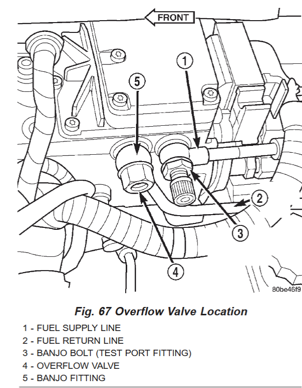
It appears that the lift pump is doing its job. Were you able to hold a specific pressure - say, 15 psi - while you filled the bucket? Overflow valve removal, testing, and installation from the FSM below. No o-rings, just two sealing washers at the banjo fitting. If the sealing washers appear to be okay, I would re-use them - just carefully check for leaks after reassembly. John REMOVAL, TESTING, AND INSTALLATION The overflow valve (pressure relief valve) is located at the outside of fuel injection pump (Fig. 67). It con- nects the fuel return line (banjo fitting) to the pump. The valve has no internal serviceable parts and must be replaced as an assembly. Two sealing gaskets are used. One gasket is located between pump and banjo fitting. The other is located between the banjo fitting and end of valve. A rubber tipped blow gun with regulated air line pressure is needed for this test. (1) Clean area around overflow valve and fuel return line at injection pump before removal. (2) Remove valve from pump and banjo fitting. (3) Discard old sealing gaskets. (4) Set regulated air pressure to approximately 97 kPa (14–16 psi). (5) Using blow gun, apply pressure to overflow valve inlet end (end that goes into injection pump). (6) Internal check valve should release, and air should pass through valve at 97 kPa (14–16 psi). If not, replace valve. (7) Reduce regulated air pressure to 10 psi and observe valve. Valve should stay shut. If not, replace valve. (8) Install new sealing gaskets to valve. (9) Install valve through banjo fitting and into pump. (10) Tighten to 30 N·m (24 ft. lbs.) torque.
-
I am assuming that there is a return flow line to the fuel tank that is directly connected to the FASS pump. Did you measure fuel flow returning to the tank during your test while the lift pump pressure was at 17-19 psi? This is important. In all of your testing, you have mentioned various fuel pressures, but you have never mentioned flow during the test. Maybe it's flowing lots of fuel at the pressure stated, but we don't know that because you have not mentioned anything about flow. If your return flow was low during the test, it would not necessarily condemn the lift pump - there could be a suction restriction to flow, which could show the same symptoms. If your return flow was high and steady during the test, it would show that the lift pump is performing as it should and that there is no suction restriction (at least for the duration of the test). An idling engine returns about 18 gph of fuel to the fuel tank through the overflow valve. The overflow valve is downstream of the VP44's internal fixed displacement vane pump. This internal vane pump's pressure is regulated at over 100 psi. All fuel must pass through this pump - there is no bypass. Even if the overflow valve offered no back pressure, the fuel return volume will remain virtually the same, consequently lift pump pressure will remain the same. So, I am not saying that an overflow valve cannot be your problem - I am just explaining why I don't think it is your problem. And, your case will be the first one that I know of, if it turns out to be your problem. It is certainly easy enough to remove and test the overflow valve with regulated air pressure. Here you mention fuel pressure, but not fuel flow. Fuel pressure tells you that there is a resistance to some flow, it just doesn't tell how much flow. If the flow is not enough to meet the demand of the VP44 internal vane pump, then fuel pressure will fall. I know you will persevere. John
-
Long posts are appreciated - especially when they are informative - like yours. I'm leaning toward your new low-stall converter triggering this issue. A stock converter has a stall speed of about 2,100 rpm, so it does not put much of a load on the engine when "drive" or "reverse" is selected. Your new converter probably has a stall speed of around 1,800 rpm, so shifting into gear will load the engine much heavier, especially in cold weather. I vaguely recall that there was an ECM update (referred to as "Anti-stall") around 1999 for these VP44 trucks. I think it was geared for the manual transmission trucks, but possibly the automatic trucks as well. Maybe @Mopar1973Man will chime in on this topic. Have you tried taking the Edge EZ completely out of the circuit? John


