


IBMobile
Staff
-
Joined
-
Last visited
Everything posted by IBMobile
-
I do a lot of camping south of there at 7200' with the morning temps at 25°-32°F. The engine starts with the heaters disconnected but with a lot of white smoke (unburned fuel) and rough idle. This is why I made the grid heater bypass switch so I can use them when I need them with no 'check engine' light.
-
Remember, the populous of Seattle believe in 'Global Warming' and will pay any thing to get rid of the white stuff.
-
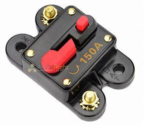
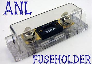
Yes, it can be in stalled to protect the alternator in that cable. Some people are using a 150 amp circuit breaker and others are opting for a fuse block with a 150 amp AMI/MIDI or ANL/AMG type fuse. circuit breaker
-
It's a little hard to run your 2 stroke boat motor on a frozen lake so sales of it are down and no need to carry it. The Walmart by my place has it for $13.84 / gal. The lake around here don't freeze in the winter.
-
Call or go into a few truck/auto repair shops and find out who they use. They are only going to use reputable machine shops because the truck/auto repair shop's name is on the line if something goes bad. With the high mile you have you might want to have the head gone through and renewed. See what they say about inspection and repair. Order of work Clean , pressure test, magnaflux, inspect valves, valve springs, valves guides. valve seats. Repair, resurface, replace valve guides and springs if needed, reface/replace valves and valve seats as needed, new valve guide seals.
-
I came across this. https://www.ramforum.com/threads/how-far-can-a-5-7-be-bored.114818/ As for low cost cylinder heads all ready built, there are a few machine shops that did videos about how bad the heads were. You get what you pay for.
-
When you say fuel system relay is this the relay supplied by Fass for the lift pump or the fuel pump relay, in the PDC, for the VP44? RELAY TEMINALS old number new number 86 1 85 2 30 3 87a 4 87 5 Most systems use terminal #86 (1) to energize the relay solenoid and terminal #85 (2) for ground.
.jpg.8841ba71f6746cc4df69b4941a3f1b40.jpg)
-
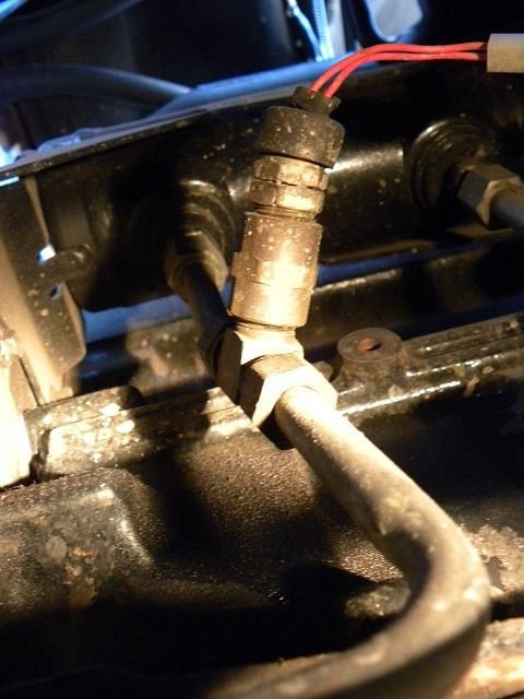
I put the trans temp sender in the line from the front of the trans to the oil/water heat exchanger. The truck is mostly used for towing a 8k lb 5th wheel. It takes about 10 miles to start seeing a reading and a normal reading between 155°-180°F depending on ambient air temp with 190°-210°F in stop and go traffic or backing up.
-
You and @MoparMom be safe in your travels today.
-
CONNECTOR TRUCK # FUCTION COLOR GAUGE --- # COLOR 1 GROUND WHITE 12-10 --- ADDED WHITE 2 TRAILER BRAKE BLUE 12 --- ADDED BLUE 3 TAIL/MARKER BROWN 16 --- 285 BROWN 4 BATTERY RED 12-10 --- ADDED RED 5 L-TURN/BRAKE YELLOW 16 --- 283 YELLOW/BLACK 6 R-TURN/BRAKE GREEN 16 --- 282 GREEN 7 BACK-UP/AUX ORANGE 16 --- ADDED ORANGE The red wire is use to recharge the trailer battery and supply added power for additional equipment such as a power winch. Determine the load and install 12-10 gauge wire with a corresponding 20 to 30 amp auto-reset circuit breaker. The added white wire is used to ground the trailer's electrical system to the truck's electrical system. The wire gauge should be the same size as the largest power wire, brake or battery, 12-10 gauge. Grounding the white wire at the battery negative terminal will give the best system performance. The wires for the trailer's turn signal/brake, marker/tail and back-up lights can be run to and fused in the extra PDC before going to the extra pin connector. Indicated below are a couple of places the truck wire harness can be spliced into for these lights.
-
So many going to hell that they had to build a highway. So few going to haven that there is only a stair way. greater lesser both evil.
-
Trailer brake controller installation is straight forward following the instructions provided by Tekonsha. I'd use the 20 amp auto-reset circuit breaker and the black, white and blue wires be 12 gauge with all connections soldered and sealed.
-
So what it come down to is number of holes (X) times size of holes (.Y") at pop pressure (Z bar) will equal a smooth running no smoke engine. If this is the case then it should be graphable.
-
I've never had to shovel rain.
-
The best stuff for cleaning deposits, varnish, and gummed up parts is a 'throttle body and intake' cleaner. It melts deposit and varnish off of parts. Mineral sprits won't do it, I've tried it in my solvent tank and after a day the deposits were still there. Mineral sprits as well as diesel fuel will work as a degreaser.
-
It's been 44 years since the last time I shoveled snow from my driveway. Do I miss it? I'll let you know in another 44 years.
-
This is to put you headlights on a rely and take the high amp load off of the headlight switch. If you're running H6024 halogen blubs then the high beam amp load would be about 10 amps at the switch. With the relay it will be about .2 amps. 18-16 gauge wire will be fine with a 15 amp fuse. The fuse and relay can be mounted in the spare PDC. Cut the red/yellow wire about 2"-3" from the connector at the headlight switch. Connect the red/yellow wire from the head light switch to terminal #86 of the relay. This is used to energize the relay solenoid. Connect terminal #87 of the relay to the red/yellow wire that is left and goes to the headlight dimmer switch. This will bring battery power to the head lights when the head light switch is turned on. I'll have another diagram for the brake controller tomorrow, I hope. In the diagram below the wire runs are numbered with the number corresponding to a color.
-
I thank the Chicken Man for the recognition and will display this wonderful symbol of achievement at a prominent place within my home.
-
There should be battery voltage at both sides of the fuse and terminal #30 of the relay. ECM voltage at terminal #86 when ignition switch is first turned on (5sec) and when starter motor is engaged (25sec) and battery voltage at terminal #87 at the same time. Terminal #85 to ground should test < 5 ohms. With no voltage at the fuse I'd check the wire and connection from the fuse to the power source, either the battery or PDC.

-
The answer to that age old question.
-
Bought a reman starter from NAPA 8/21/08 for $189 with lifetime warranty. I put about 54k miles on it. If you by any part for your vehicle that has a lifetime warranty on it do two thing. 1. Make two copies of the receipt. Put one copy in an envelope with a copy of your registration and proof of insurance. If your vehicle brakes down while on the road you have your part warranty with you. This helped me when the crank speed sensor went bad while I was camping in Moab, UT. Pulled the copy of the receipt from the glove box envelope, O'Reilly's, gave them a call and part good in stock. Fixed that day with no charge. 2. Put the second copy with the original receipt and file it away with other important papers for that vehicle. A lot of store receipts go bad, the printing fades after a year, so hopefully the copy will last longer.
-
Is it true that in Oregon if you don't drive your truck every day then moss will grow on its north side.
-
From: Candlepower.com Technical bulletin: 9004 & 9007 blubs "The 9004 (HB1) bulb, introduced in 1983, was the first halogen replaceable headlight bulb available for use in North America. It uses 12 Volts, has a 45 Watt low beam filament producing 700 lumens, and a 65 Watt high beam filament producing 1200 lumens. These filaments are transverse—if you hold the bulb upright, they run across the bulb from side to side. " What's 5 watts up or down the blub still sucks.
-
What type of head light do you have? A 6014, H6024 / 6014 Halogen, or L6024 LED. This is needed to determine fuse and wire size. How many axles on that trailer? Need this for controller circuit breaker and wire size to trailer. I've mapped out the "lamp wiring diagram" for the F250 for which wires to splice to, relay power and switching. I need to know how you want it incorporated into the truck. Are you going to use the salvaged PDC for this or put something else together? Are you using a Dodge PDC in the Ford now to support the Cummins and if so can part of that be used for the relays and circuit breaker. These are the size connectors that I salvaged from a PDC.
-
@JAG1 looking where to toss the bolts in @Mopar1973Man truck.


