


Haggar
Unpaid Member
-
Joined
-
Last visited
Everything posted by Haggar
-
It all SHOULD come back to the battery. And that is the OPs point. According to the FSM so far that we can see, the main grounds go to the block. The two other items that we consider groundable are electrically isolated from the block. The only reliable return path is through the 8 and 10 gauge wires. G115 and G120 go to the body. (they are both 10 gauge) G118 goes to the frame (a single 8 ga) The 8 ga off the primary battery is intercepted and spliced into the ground circuit for the wiring harness without touching the body engine or frame. Ampacity for a given wire is determined by voltage drop and temperature rise (so length of wire makes a huge difference, so do connection splices etc.), so use my numbers with a grain of salt. 10 ga (under 4' length) can handle up to 85 amps. and 8 ga under 4' length can handle 100 amps. So, in all reality, the wires supplied originally are just fine for the amps and the length. (you have more than 130 amps at the body, and more than 100 amps available on the frame) (just for giggles I ran the 0ga.... its probably fine for 1500 amps..) This is for new wire and no de-rating for connections.... As our wires get older and corrode, and the ring connections are rusty and nasty.... available return path current degrades. So my take from thinking through this: The original design is fine, but with little to no room for error. This is why the WT ground mod works so well. Our trucks are older and especially for the guys at the rust belt and north (or coastal guys too) corrosion is making grounding marginal. Just my $0.02 HTH Hag
-
Awesome question. It made me look at the ground distribution better. I am not seeing a bonding ground between the engine block, frame and cab. It probably wouldn't hurt to add one. Just like the old gassers, the braided wire straps with ring terminals on the end. Anything electrical that the return path not directly connected to the drive train, has to either take the high resistance route through the springs, shocks engine mounts, or on either the 8 or 10 gauge wires to either battery. I have not had the engine out of this truck (thats when you run into the bonding jumpers) so maybe someone who has pulled a motor can chime in whether they exist or not. Next time I have her on the lift, I will look really hard. I may just go ahead and add a couple. Thanks! Hag
-
VIN is Vehicle Identification Number. Its on the dash. The same one the state uses to give you a title. please take all things with a grain of salt. We are south of the border. You canuks could have mandated all kinds of weird stuff The reason they are asking, the manual transmission trucks got an HX turbo and the automatics got the HY turbo. (again Canadian emissions could have been different.) Most people upgrade to the HX from the HY at this point. But there may be some modifications needed along with the change. Some people are happy with what they have (they don't pull heavy loads, and want a simple repair) and just put an HY back on. Post a couple pictures of the turbo, especially the exhaust output. Many of the good turbo guys here can tell you what you have with some pictures. HTH Hag
-
oh by the way, DF I like your shield it seems so simple (and you did a nice job of fabrication!). Hag
-
Each battery on the negative side has a zero gauge, an 8 gauge and 10 gauge connection to different parts of the chassis, body, and engine. (I attached the FSM page of the battery ground wiring.) If those connections and wires are in good shape, it should be fine. There is enough ground for the starter to work, so 400+ amps. I wouldn't worry at all about small things like lights etc. If you add a winch, you need a new ground wire from as close to the battery as possible. Don't use an existing ground wire for your new equipment without looking at it in a detailed manner. If you drill a hole in the frame and add your ground there, you should be golden. HTH Hag 2001 FSM Ram 8W-15-11.pdf
-
I ran some quick numbers and looked some of my old heat transfer stuff. (I could spend a day modeling it and still have a lot of questions on the variables.) Since the exhaust pipe and cooler do not touch, there is no conduction. When the exhaust is hot, you are moving down the road and the air is passing by, so no convection to each other, but cooling to the atmosphere happens. The only mode of heat transfer is radiation. (remember from the other thread, radiation is driven by emissivity...) It comes down to a simple heat shield will in most situations reduce the radiated energy by half. (watts/foot) (I agree yes/no lets sit down with lots of beer and argue the finer points...) Now that is radiated heat, not actual temperature. Radiated heat is like at a big bonfire how your face and arms will feel like they are starting to sunburn (radiant heat) but when someone walks between you and the fire, you are all of a sudden you are cool. (they blocked the radiant heat) Insulation seems to work better on paper. (according to a spreadsheet I am running.) 6mm of the right insulation reduces the lost heat energy to 1/5. (I thought the heat shield would be the same or even slightly better. It may be, as I didn't factor in the the heat loss of the air moving by the surfaces...) It looks like wrapping the area or going to a ceramic coated exhaust in that section would really cut down the heat transferred to the transmission. HTH Hag
-
I am with Katoom on this. (and also on the strange de-rail of the original topic) I think Gale has some interesting theories, but I think there is no update on the video because the data he recovered did not support his hypothesis. I understand he is worried about the "stirring" of the fluid as it hits that abrupt stop in the casting. But that amount of "work" is NOWHERE near the amount of heat generated from the sliding action of the hypoid gears. That shearing and torque transfer is by far the greatest heat generator. Now since we added some more fluid to the system, the amount of time it takes to get that much fluid hot and try to keep it there.... I just think it didn't/doesn't add enough work to be a problem. I really think in all you are better off. (I have a new diff cover to put on and will still do it.) His worry about the new higher fluid level has some merit. You will lose hp (and therefore efficiency) the deeper the oil is you need to drag anything through. But the new higher level may bring the axle tubes more into the cooling situation..... the efficiency "lost" may still be very small compared to the power required just to turn our ring gears, huge long axles and the awful unpsrung rotating mass on the ends (tires and wheels especially on a dually.....) Anytime you drag a rotating mass in a sump of oil, foaming is a possibility. Our axle lubes are designed with anti-foams in them.... I cannot think of a single on road automotive or industrial differential that is not dependent on splash lubrication. This is not a hydraulic pump or valve application where air entrained in the fluid can be catastrophic. I think that entrained air between the hypoid teeth is not an issue because the viscosity of the fluid and the large contact area allow the teeth to compress or expel the air, but the teeth do not come into metal to metal contact. TL;DR I don't think Gale got the results he expected and so never reported them, or is inspecting his system/test rig to find out what is "wrong" with it. I am pretty certain other losses in the system create more heat and make his worry so small as to not be noticed in the data. HTH Hag
-
Katoom, Any infrared measurement is factored by the emissivity of the surface. This is mainly a color thing, but is also actually affected by surface finish. In the calculations (internal to the device) the emissivity has a range of 0.0 (a mirrror, no infrared thermal emission) to 1.0 (perfect black body, perfect infrared thermal emission). most inexpensive units you cannot adjust this value for actual emissivity. Its generally in the range of 0.95 and that is good enough. (there are other problems with inexpensive ones, how they average the pixels, spacing between the pixels etc) A good test is find an area that has been out in the sun for a bit with both a white and black surface. Measure the temperatures of both. (black will be closer to the 1 white will be closer to the 0) see what "temp" each are knowing that both are really the same temperature. This will give you an idea of the range your "temps" are based on reality. Infrared is great for relative temperature measurement. It lacks a lot for absolute temperature measurement. (what is fun play with a mirror sometime, when you have a fire in the fireplace or such. The infrared gun/camera reads the reflected temperature, not the actual temperature of the mirror. You can hold a 1,000 degrees in your hand!!!!) TL;DR there is a couple degrees difference between your measurement and the actual temperature. The shinier it is the more likely its off. GL HTH Hag
-
Sorry didn't see this until today. Hag 2001 FSM Ram 21-770.pdf2001 FSM Ram 21-768.pdf
-
I attached the page from the 2001FSM on how to adjust the linkage. HTH Hag 2001 FSM Ram 21-769.pdf
-
Hmmm, How hard are you going to push this truck and are you going to use it as a tow rig? Are you going big on boost pressures or stock? The reason I ask, if you are going to be easy on it, you won't be making much boost and therefore IAT shouldn't go too high. The opposite is true if you are going to tow or really horse it. You are just gonna have to think about it some. If you do finally need to cool it, will you have good room to get your water sourced cooler in there somewhere? I guess just start visualizing what you would have to do to get something in there later, and will it be easier then or now. A benefit of moving the motor back some, is you are moving the Cg back some which will help with steering (less weight on front wheels) and traction (more weight on rear wheels.) but I am saying that without know the cowl to block clearance etc etc. just my $0.02 Hag
-
ahhh, but those voltages were in reference to battery ground. they need to be to sensor ground. lets try that first. Hag
-
Ok, when testing this the "ground" should be sensor ground not truck ground. That said, in most cases, you can swap those. But any questionable voltage must be retested to the correct ground.... Yes in step 3 they are asking you to read the sensor lead (Grey red). BUT I worry that something is supposed to go on in the computer. (remember they are asking you to read this voltage through the DRB, not directly at the sensor) The reason I say this, There is very little difference in manifold pressure from the truck idling and off (on the pressure side.... do we actually go into a vacuum state at idle? I don't think so but I didn't get a pressure gauge with vacuum too.... so really don't know) but they are EXPECTING a huge voltage change. (0.2v running 2.35 volts kOEO) Didn't you get one of the bluetooth obd things?(that uses an app on your phone?) that should show you the map sensor output so you are checking it like this DTC check system is. What voltage do you get at the sensor lead with the ignition on but engine not running? Hag
-
grrr i forget yours is newer than mine..... I will try and find the wiring diagram for an 02 and take a peek. Hag I looked at the 2002 manual. The page is the same 8w-30-33. It shows the same splices S165 and S166. So I think it operates just like the picture shows, you just don't have the splices apparently. when you were checking for voltage, were you doing this with the map sensor connected or with it disconnected? where did you have your ground connected? (while checking this?) The way you should look at this circuit is: Map sensor plugged in. ( you will need to "backprobe" the connector with paper clips. DO NOT LET THE PAPER CLIPS TOUCH!!!) meter ground connected to sensor ground. (not vehicle ground. they are different. they COULD be the same, but not necessarily) Now you can check to see (with the other probe) what the 5v reference is. (it should be almost exactly 5v.) Now you can then check the signal back probe. This should change with manifold pressure. p0237 is expected map voltage is too low. (I am totally guessing here, i can't find a reference as to the sense in the manual. I am guessing 5v is near max pressure and 1.5vor so is low pressure. P0236 is map sensor too high too long so i think that means high voltage is high pressure)So I guess that during low manifold pressure the 5v is brought down low BUT IS NOT ZERO. (this is how the computer knows if the map sensor is disconnected or bad.) I found this (starting to get up to speed with you guys) I am a bit confused as they want to see a 0.2v map sensor with it running but 2.35v with the engine off.... but by doing the above with the back probes you will see what the DRB would be reporting to you. ( I will try to look tonight to see if my snapon reads the actual map voltages like the DRB. there should be more than 0.2v with it running. maybe it switches ground references depending on if running or not or is it a misprint.... grrrrr. anyway 18 is way out. Hag
-
The signal should never be 12v...... The map sensor is supplied 5v (positive) relative to the sensor ground. The map sensor is basically a rheostat (like the volume knob on an older radio) It cannot have an output higher than 5v. it is supposed to vary between 0vdc and 5vdc depending on pressure. If you are seeing 12v there is a definite problem. If 12v is really getting there, it is sourcing itself from another system. I attached the FSM page of the oil pressure and map sensor. Hag 2001 FSM Ram 8w-30-33.pdf
-
No neither systems talk to the PCM. The wipers get timing information from the CTM, but should still work on low and high without a central timer. HTH Hag 2001 FSM Ram 8W-62-2.pdf 2001 FSM Ram 8w-53-2.pdf 2001 FSM Ram 8w-53-3.pdf
-
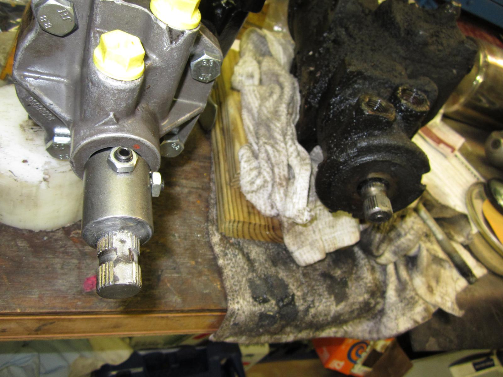
Here is where I ground the flat on my adapter for the Borgeson
-
Dave, Take a look at this post here. (this is a DHD yours may be a DLD or some other, but they all work similarly. You only need to know exactly what you have when you go to get parts.) Well it is one of two things.... No chain or no dogs. (or broken fork...) look at the exploded view. Notice that there are two forks 51 and 54 one is range and one is mode. I think your range fork is working (you get high and low) , but your mode fork is not. It could be that the fork pin 53 is now missing. (fork just slides on the shaft) this is rare. The more common failure is the pads 49 and 50 are gone. there is just not enough stroke to engage the synchronizer sleeve 29, to engage the drive sprocket 20. You are going to have to split the case to see what your problem is... it is not in the tailshaft section. I agree usually a chain will ball up in an area too small for it and cause catastrophic damage. I imagine it is possible to break and go to a safe spot. I am betting the mode fork is your culprit. GL HTH Hag
-
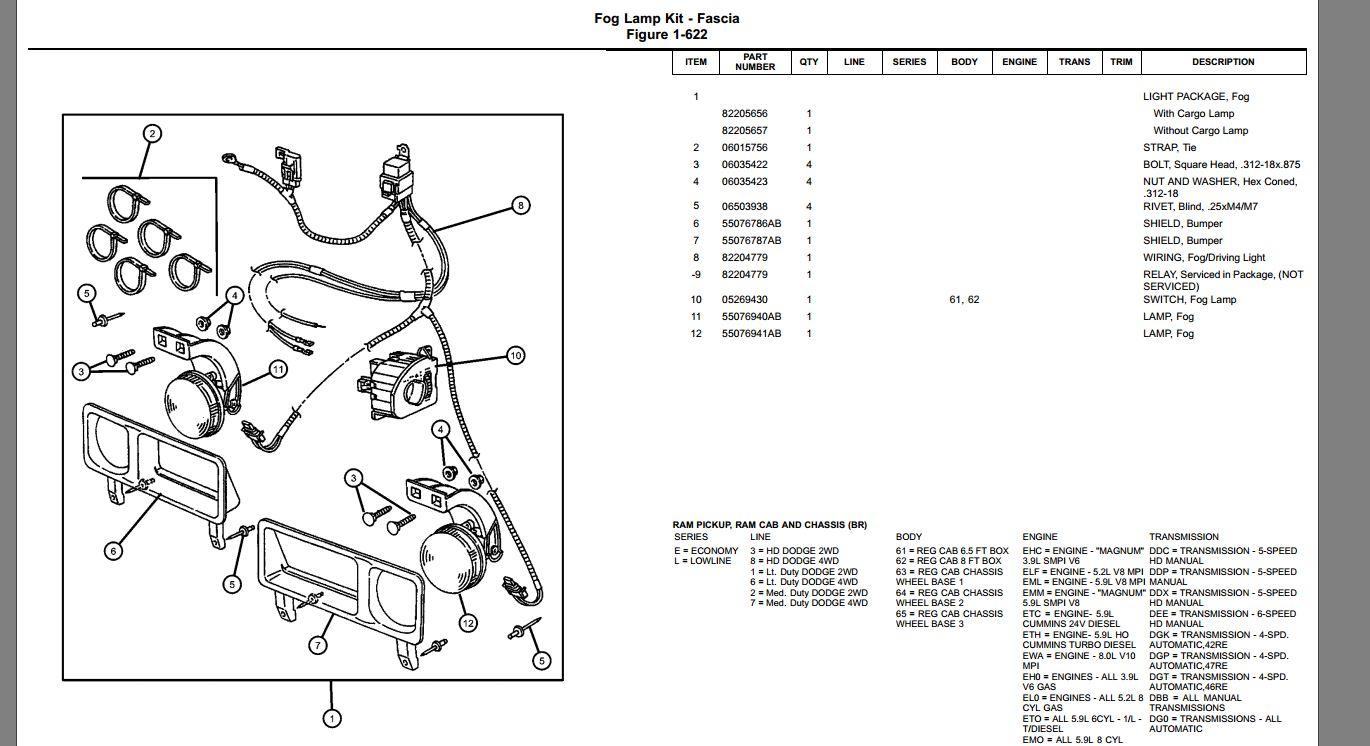
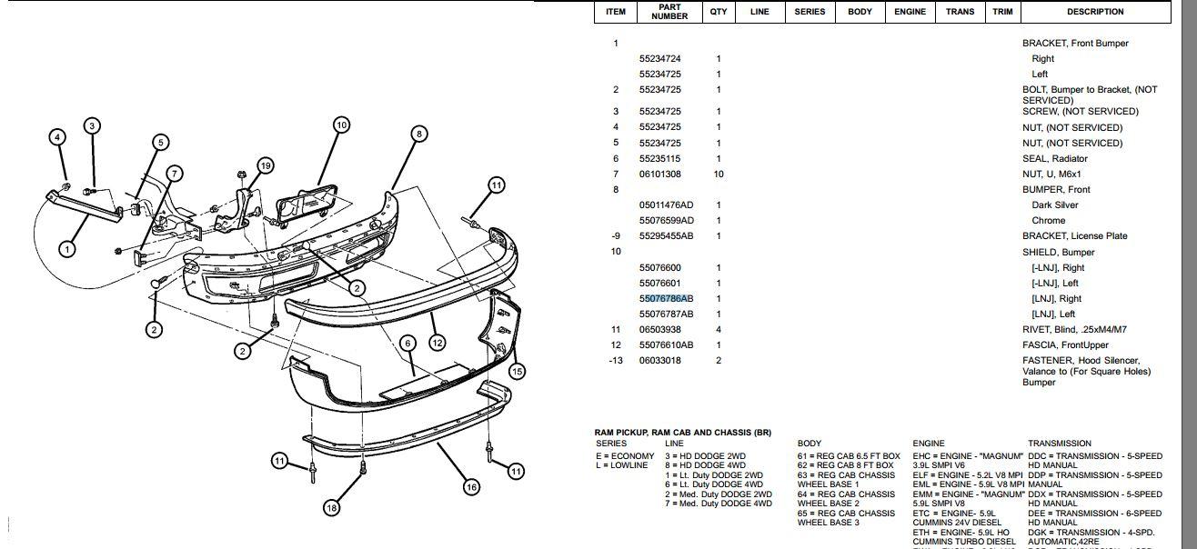
not all trucks came with fog lights. Pretty sure the bumper is exactly the same, but the plastic pieces that bolt into the rectangular holes is different. Looks like LNJ was the code for "with foglights"
-
Dave, since you get the 4wd light on the dash, the actuator is moving. (notice the 4wd light switch is at the end of the stroke of the actuator.) the actuator moved, but did the collar move is our question. Put the front axle on on jack stands. (I assume you have an Auto truck, so put it into neutral.) Idle the truck (so you have vacuum) (or supply the vacuum yourself with a hand pump. <--- I like to do it this way so i don't have to listen to all the rattling...) put truck into 4 hi or lo (transmission still in neutral.) prevent the TC output shaft or input to the front differential from turning. (you can do this with a pry bar in the universal joint somewhere) Spin the left front tire by hand. The right front should spin the opposite direction. take the transfer case and shift it out of 4wd to neutral or 2 wd. Spin the left front tire. the right front should not move. (it is no longer connected to the differential) If the above works fine.... Problem is most likely in TC, but you can check it out. (try by hand first, but you can do this with engine running and a friend watching.) Jack up the rears to match front. put TC in 4wd put trans in neutral. turn the FRONT drive shaft (axle to the TC) the rear drive shaft should try to turn. If you have a buddy, you can do it with the engine on. In the 4wd modes. the front TC output should turn in 2 wd on the rear should turn. (idle is fine you don't need much) There are shift fork dogs that go bad in the tc (you coulda wadded up the chain but that usually is catastrophic and externally visible) I don't think ours has a clutch in it (some of the later model gms do) or there could be gear problems in the planetary, but I think you would HEAR that.... GL HTH Hag
-
Dobber, Check out the Apps. Make sure it is not the problem. Try a different ECM. (I was able to swap my brother's and mine to confirm it wasn't the ECM) This is a failure mode of the VP. My brother's died this way. No codes ever. But when cold it was dead pedal. If you let the truck warm up, it would run normally. VPs really rarely fail this way, but it does happen. Our mental model of the problem is a cracked solder in the wiring to the fuel metering solenoid. Fuel volume is not increased as the apps increases voltage. (the crack in the solder closes with the thermal expansion of the pump. allowing it to begin working normally.) There appears to be no confirmation programming (and therefor set a code). In most gas cars there are some lines of code that relate TPS voltage and engine speed. (this is usually in the Idle speed control circuit, but i am seeing it more in other areas) but the code uses a bit of logic: my commanded engine speed is increasing, but the actual engine speed is not increasing. Hope you find your troubles! GL Hag
-
Ronnie, I hope they come off for you... they can be a pain!!! You may want to try a little bit of heat too, if you have a heat gun (or just a hair dryer.) this also may help working some penetrating oil in there. In the old days of US cars, the wipers had a center bolt. So you could use a special puller (like a gear puller) to get the suckers off..... Hey just think, this (the new clipped slip ons) saved a good 3 minutes per vehicle during manufacturing!!!! It doesn't matter that it is a nightmare for you now! Hag
-
Ronnie, I have had them stuck before too.... Spray a bit of penetrating lubricant in there. With the lock in the out position, I use some small pry bars, and slowly and carefully put some upward pressure on each side of the wiper arm. Wiggle, pry, wiggle pry, spray more oil. Eventually it will slide off. Some of the issue is the wiper arm is to one side, so when you try to pull, you make a rotating movement and the splines don't want to separate. The trick is even parallel pressure. HTH GL Hag
-
Ronnie, The wipers SHOULD stay powered until it trips the park switch. So something is wrong there... I have not played with the chrysler wiper motors, but the GMs you could get into and see how the park switch worked and test it out. I see you are in UK, so i am guessing a new wiper motor is not an easy trip to the autoparts store. Be careful. The diagram I attached is a 2001. The wire colors may be wrong, but I think you could use it to test your system. you will at least be able to see if you are getting the proper 12v signals on the high and low commands. GL HTH Hag
-
No worries it is cold as the dickens here, and we are the sunny south! I put a description of where your trouble may be if that light stays on bright. Take a peek at it when you get a chance. Hope we can solve it. l8r Hag

