


Haggar
Unpaid Member
-
Joined
-
Last visited
Everything posted by Haggar
-
I am agreeing with the other guys, get someone to look at it. It is quite possibly fixable. (I would) Do keep in mind, your vacuum pump coupling may have died. I can't explain it, but frequently front end collisions will damage this. So don't sweat it if the power steering seems to fail real soon. It is just the coupling. Do a reseal on the vacuum pump and replace what is damaged. If you have questions look up fixinrams.com (Gould gear) super nice gentleman to talk to and knows those parts in and out. Yes to fix the oil pan you have to lift the motor a few inches. I don't think anyone has successfully done it without lifting. (we have seen pictures where someone cut the cross member, but I really don't suggest that.) Good Luck! Hag
-
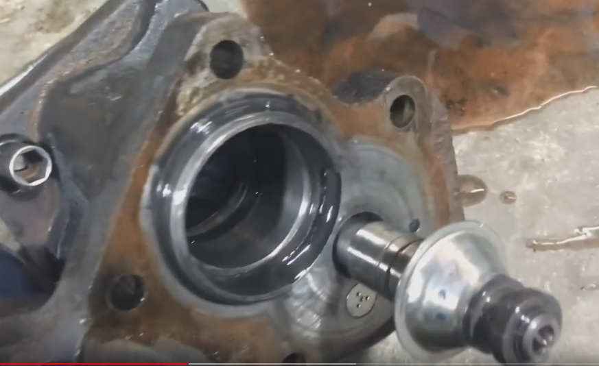
Did you leave the rod attached to the booster and only take it loose from the pedal? The length of the actuation rod is extremely important, and any change in that could cause the issue you are having. (that was why I asked how you removed it.) I know you don't want to take it apart. But it usually seems the problem with self actuation after repair is the primary valve spool is in the wrong position at rest. Power steering fluid from the pump is allowed into the boost section without having to move the pedal. I don't know exactly what the problem is. I have never experienced it. A few people have. A couple solved it by disassembling and correcting something. (of course they never list what it was, and may not have known what they fixed.) I swear I remember that there was a part in the linkage from the primary valve to the power piston that could be assembled backwards. I have no pictures of this in my records, so my memory could be muddled. And I think the way you did the work, you did not take that assembly apart. Did yours come apart like this? (the primary valve stayed stuck in the main body?) You have to make certain the ratio lever connected properly into the groove on the primary valve. Note: I have done a bit more researching..... Its a fairly rare problem but happens. Some say it can be dirt in the check valve etc. I hope you can find it. I am thinking it is something simple during reassembly. GL HTH Hag
-
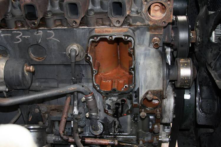
Don't agree with me. I am taking a total wag at it. I just found it interesting that a picture from another engine shows something machined in that area. I cannot find a really good oil or water flow schematic that really shows what is going on exactly near the oil cooler like that. Get it cleaned up, I hope it will be blatantly apparent what the hole was for. (maybe no plug and it is supposed to be there....) This looks like a 12v motor but that hole looks machined and no plug.....(but doesn't look like water got on it either....) Ok so your new question then, is why did it appear to have oil "flowing from it" . (the oil didn't originate there, or did it?) Edit (the crazy forum keeps pushing these replies together.....) If you are worried that there is a crack you will need to pressurize that orifice and see if you get air coming out of the oil gallery. There should be no communication of the oil gallery to the water jacket. (you may have to remove the water pump and or the elbow just to the right of the area you are working to stop the flow of air there to get pressure in that passage.) Otherwise it has to be oil from the oil cooler. HTH Hag Sorry Jack, it keeps adding these to the other reply I just made. lol
-
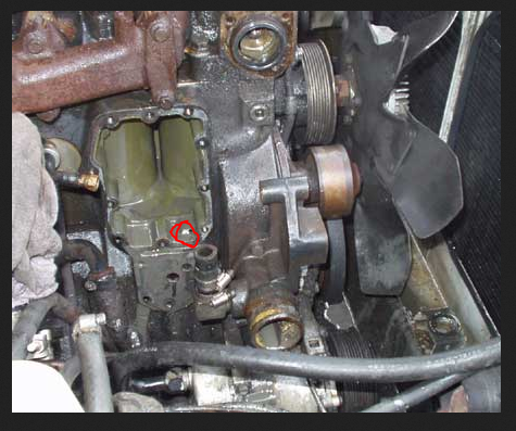
Oil gallery plug should be there. I am betting it will become apparent when you get it cleaned up. Looking for more pictures,but look at this one (I circled it in red). I just don't know if it was a threaded hole or a peened ball. HTH Hag
-
D, Something went really wonky in the hydroboost. (it should not self apply.) Somehow you are getting pressure past the primary valve and into the boost cavity without actuation. I have seen this during reassembly by getting the ratio leaver installed incorrectly, but usually the pedal to the floor happens almost immediately. I wonder if yours didn't do it immediately because there was insufficient fluid in the system until you bled it a bit? Take it back apart and look for dirt, trash or anything not allowing the primary valve spool to seat properly. Did you disconnect the rod from the brake pedal? or how did you take that part out. (this is very important) HTH Hag
-
When you look at the schematic, you will see that the 12v source is basically constantly provided to the blower. (the power runs through fuses and the relay, but the relay closes the path when the ignition is in the "run" position. So 12v positive in reference to the battery negative directly should always be "hot" or "on" The controls on the dash in combination with the resistors change the relationship of this 12v+ with reference to ground. (by adding resistance to ground, the motor "sees" less true voltage than 12v. ) So the trick is to get your mind around, there will always be 12v+ available. It is the ground reference (how the blower motor "sees" the ground) that is most likely your problem. You are going to have to do two different checks to see where your problem lies. 1) connect a volt meter red lead to the blower hot wire (Dark Green on the 2001) and use the chassis as your ground. (not the ground to the blower motor) (your 12v+ should not disappear at all.) 2a)leave the volt meter positive on the dark green. place the negative on the black tan wire to the blower motor. (this should read 12v on high, and lower voltages on the lower speeds. It should show up immediately with the key placed in the run position.) 2b) alternately you can change the volt meter to "resistance" or to "ohms" and connect it between the black tan wire and chassis ground. (there should ALWAYS be continuity to ground. The actual resistance number should be steady and only change with speeds..... The resistance to ground should only go to "open circuit" or "no continuity" when the mode selector is in the off position.) You will want to rig this up so you can have it ready to read before you start your truck in the morning and try and catch why there is a delay in the power. and sorry I am mechanical, so my electrical explanation may be a bit incorrect, but I hope you are getting the gist of it. Hag
-
GS It is going to take a bit more investigation then..... (I attached the wiring diagram from an '01 manual) You will need to connect a volt meter to the hot to the blower (and reference to your own ground elsewhere) to see if your 12v positive stays available. Here is the FSM of the controls. The blower speed is referenced to ground through the switch on the dash (and based on your selection for speed.) What could be happening is your reference to ground may be going away. G201 is in the right center support of the dash. But if it were completely loose you should be complaining about other things. I think your problem is closer to your control on the dash (the connector or the multi-layer switches.) HTH Hag 2001 FSM Ram 8W-42-4.pdf
-
To troubleshoot my brothers '01.5, I swapped my '01.5 ECM into his. He has an automatic I have a manual. His truck seemed no different with my ECM in it. His in my truck was immediately noticeable. His ECM does not have the stall control that my truck had. So I couldn't just let the clutch out, like I can with my ECM. Other than that I had no troubles back and forth. But they are very close in manufacture date and I think the partnumber on one of the lines of the ECM was the same. (but obviously had different programming) mine is a base model truck and his was an SLT but i don't think it was the highest level one with theft prevention and such. Hag
-
To find the bad ones. You have to have someone you trust on the wheel to move it. (luckily I trust Helga!!!) (the reason you want someone paying attention, they could crush your hand if not paying attention.) I put my had completely around the tie rod (ball joint or whatever components you are testing) so my hand touches both the tie rod and the steering knuckle in this example. While Helga is "sawing" ( that is a perfect description drip!) the steering wheel, I close my eyes and just feel the two parts in my hand. I am trying to feel ANY motion that is NOT what it is supposed to be doing. In tie rods, you will feel the tie rod move, and the steering knuckle not move for a second, then move. or if the idler arm is bad, the tie rod will wiggle a bit, or twist as it is trying to move the wheel. When the parts are brand new and tightened properly, the entire unit moves as one piece. As the parts begin to wear, they have differential movement. I do the same with ball joints and trac bar, but have friends jump up and down on the bumper or set up ladders so they can step onto or off of the bumper etc. HTH Hag
-
I too have had a master cylinder seem to bite the bullet during a brake overhaul..... (was it semi-bad before the job and didn't live through bleeding? Did i do something by pushing the fluid backwards???) I don't know... it is frustrating though sometimes!!!!! the cylinders SHOULD push back without damaging the master/ABS etc....at rest the fluid reservoir should be in direct communication with the wheel cylinder piston. (no valves closed, no seals in the way) It has definitely added to my grey hair!! Hag
-
Yeah give it a shot again.... One of my suburbasauruses drove me nuts!!!! It took like 3 weeks until I found the gravel road trick, but I had to have someone with me and bleed them right then too.... total PITA! But worth it. I like rock solid brakes! Good luck! Hag
-
Unreal, While it is possible the hydroboost magically died, when you were working on another completely separate part of the system, it could happen. My guess is that probability is less than 1%. The easiest way to prove this is: are they mushy with the engine off? If they are, then it is air or trash in the brake lines. (a small amount of air will feel a LOT less mushy without the booster. The booster adds like 500% to your application force.) I am guessing you have the 4 wheel ABS, like I do. It is VERY easy to trap some air in there and have issues with soft pedal. When you pushed the pistons back in for the new pads, did you relieve that fluid, or push it backwards into the master cylinder? I used to push it back, but have in the last 10 years, quit doing that and relieved it. This keeps from pushing trash into the brake combination valve and into the abs system. You may have to play some games with the actual bleeding procedure you are using, and you may want to force the abs to operate a bit. (if you have a bi-directional scan tool, there is a brake bleed procedure) or you can find a gravel parking lot and force it to operate and bleed it. (I don't know if this abs is like the GM's where you can manually open the abs valves.) GL HTH Hag
-
I really like my Dodge off road stuff. He can have delivery problems apparently though. I think if you look through most posts, that is really the only complaint.... I have never noticed one on quality of the product. I was not in a hurry for mine, so I don't remember if they came in quickly or not. HTH Hag
-
That picture is from the '01. (scary i just noticed the picture is of a P-Pumped engine.... ) Anyway HTH Hag
-
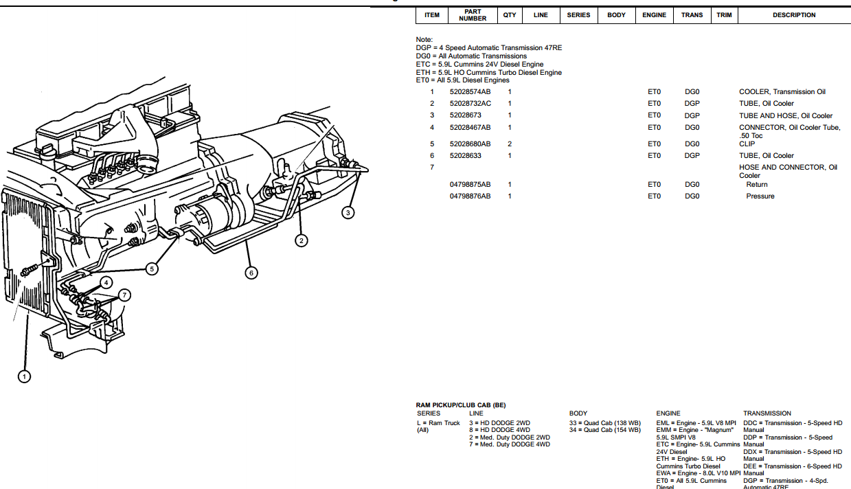
cooler lines are under the cooling section (group 7) here is what the pictures look like.... don't use these numbers I don't know what year yours is. but this is what you are looking for.
-
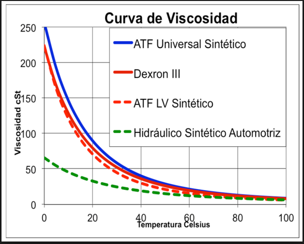
Katoom, That is an interesting play in the brake pedal. My truck is not here, but I will try to look at mine this weekend. My first thought is "is your accumulator working properly?" With the truck off, you should have 2 to 3 fully boosted brake applications before the accumulator is drained. My truck, with the engine off, the next two brake applications "feel" just like the engine is on. The third application feels odd, and the 4th the pedal feels all wrong..... Sorry guys I couldn't stop the comparison.... Katoom has the baby bear cooler, NIsaacs has the papa bear... so that makes mine the mama bear cooler.... Here is a neat chart (sorry it is in spanish) but 20C is about 68F (and 100C is 212F). The viscosity grows significantly in the colder temps. So your steering could feel "sluggish" in the really cold. (yes this doesn't show "power steering fluid" but it does show ATF (how bout you auto boys in the winter?) and the Viscosity/temperature curve should be similar) I have not noticed a cold weather problem in mine (but of course here, our frost line is less than a foot, and we are lucky when we get snow), but my system will start to whine more when I am in the woods, going slow and turning constantly maneuvering around trees and stumps and stuff in the summer.
-
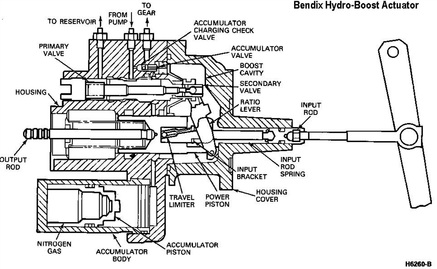
Nissacs, Here is a great article I found. It has the best drawings for how the hydroboost control valve position moves and what ports are exposed. http://www.brakeandfrontend.com/operation-diagnosis-and-repair-of-hydro-boost-power-assist-systems/ In the hydroboost, the control valve blocks the return (but keeps the pump input connected to the power steering gear) so there is no return during "no brake" operation other than the leak around the control valve. (this means that a leak in the control valve CANNOT self apply the brakes....) It is hard to imagine, if you have not seen a system like this. Otherwise it is similar to some of the more simple hydraulic systems, it is more a function of system response time. Our steering gear works similarly. The control valve does not apply power to help turn one direction or the other until it is told to. There will be "some" return flow. These valves leak by a little bit internally. HTH Hag
-
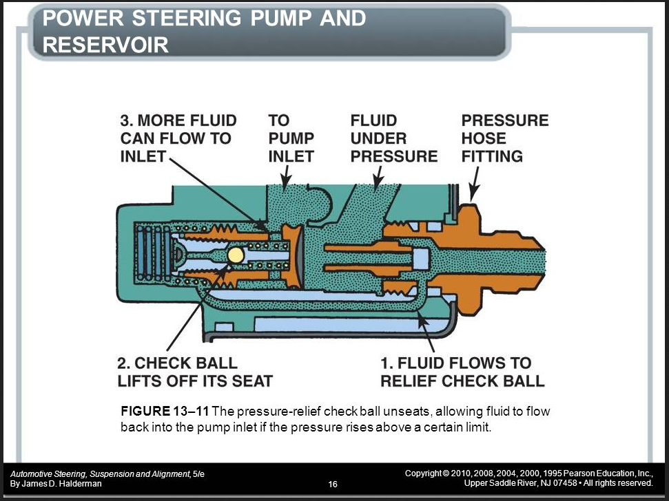
Great pictures! Yes, in the wood splitter hydraulic circuit, when the spool is in the center position, any flow from the power unit returns directly to tank. If you watched the pressure gauge shown, it would only show a few PSI. Just the resistance of the flow in the tubing and the spool to return the fluid to the tank. In our system there is this in the bottom of the pump.... The "fluid under pressure" is the pump output. This circuit allows the "pump output" to cycle back to the "pump inlet" under certain pressure and flow conditions. (but at the cost of small passages causing heat from work) But all the green dots coming out of the "pressure hose fitting" are under pressure when the pump is turning (engine is rotating) This is a parasitic loss. Probably a 1/4 to 1/2 hp at idle and up to 5 or 6 hp max. (engine full speed etc) This is why there has been a move to "electric steering"... cafe standards don't look at battery charge during the driving cycle. its just like VW, our car design is being forced by the almighty mileage standard and the numbers it puts up.... (is electric steering better safer? are electric air conditioning compressors better safer?) they can probably store more electricity so the steering works anytime, but only recharge the battery when there is excess energy available (during a coasting section etc.) anyway that's my $0.02. Hag Katoom, Interesting. Well you could have one wheel bearing dragging a bit more than the other. another thing to not forget, our Dodges are NOTORIOUS for internal failure of the front flexible brake lines, causing a resistance in the return flow. I have on my truck, and a couple friends trucks, experienced this. (of course we didn't catch it early as you may have...) I have a couple thoughts on your "slackness" under certain conditions. (I was truly hoping you find a bit of slop in the input rod or something.) I will try to orient those thoughts in a semi readable form. (while stream of consciousness writing is fun, it is really hard for someone else to follow....) Hag
-
NIsaacs, I think i am getting where you are at. I am sorry, it is truly a problem with many of our engineering descriptions... the language is not always robust enough... Hydro-pnumatically the names are the same and you have to know from the system what the function is.... (and I hope we are not getting hugely technical in the fact of whether it is "flow control" or "pressure control" and some of the side arguments associated with that...) Ok The "relief valve" you may be picturing is like on our air compressors or water heaters. These are designed to "relive" to prevent catastrophic failure to other components in the system. They are also there BECAUSE something unrelated to the NORMAL operation is present. In the case of the air compressor, the pressure regulator could fail allowing the compressor to keep pumping. In the hot water system, normal system pressure is supplied by the city, county or your well pump. If the heating elements stick on and don't stop heating at the right temperature, we could boil the water, and the resultant volume expansion is catastrophic. (our waste gates on the turbos, burst discs on a supercharger etc.) In all of these cases, system pressure is set by something else in the system. (notice almost all the things we just talked about were compressible fluids....) The "relief valve" on our power steering pumps, SETS the system pressure. (and should more properly be called a "pressure regulating valve"... but there are other reasons it is not called this....) If you can visualize it, our PS positive displacement pump output is directly connected to the "relief valve". When you start the car, the power steering pump immediately begins pumping fluid. Whether we have a "pressure relief valve" or not, the pump would build pressure. Since (in our case) we are not presently using any of the pressure (our foot in NOT on the brake, nor are we turning the steering) the pump would very quickly dead-head. (dead-head is the point where there is no flow and usually result in maximum system pressure...) Since power steering fluid is relatively in-compressible, and the efficiency of the vane pump fairly high, the pump would completely stall (lock up in this case) causing belt slippage break things etc. Since we have this "relief valve" "in line with" the hose that feeds the presently closed valves ( brakes not being used, steering not being turned) the pump does not stall, but all the fluid is forced through the restrictions and returned to the reservoir. When we then step on our brakes and hold, some fluid is allowed to fill the hydroboost force multiplication reservoir. the system pressure will immediately drop (we have opened a "large" cavity of low pressure fluid) the "relief valve" will close and the pump pressure goes to the hydroboost and it recieves the pressure. the pressure builds until the hydroboost reservoir is at system pressure and the "relief valve" opens again, recirculating fluid into the pump reservoir, and maintaining system pressure. The same cycle happens when you turn the steering wheel. As soon as you begin turning the wheel, system pressure drops and actually stays dropped until the wheel quits moving, or the flow of the pump is greater than the speed of turning the wheel. (any of you/us guys with big tires notice that when in a bind you can turn your tires in little spurts? or you lose your turning strength momentarily when you touch the brakes? or speed up the engine and it will turn?) Edit: So to answer your last question. Yes. The pressure lines at the exit of our pump all the way to the hydroboost then to the power steering sector are at a pressure ( I hesistate to says it is 1500psi at idle without checking.... but it is at what pressure the PS pump can make at the speed (idle) that it is running.) system flows and heads make diffferences in the actual pressures, but your pump starts pulling Horsepower the minute the engine is on. I hope this helps! Hag
-
Nissacs, You are correct (and what I was trying to explain) The pump, when no flow is being used (by the brakes or steering) is trying to flow it's entire work THROUGH the relief. So it results in a constant 1500psi available on the system. (but all of this work is returning right to the pump to be heated up some more, and some more and more) Demand sensitive means if there is no flow (no need) (the steering is not being used, or your at higher speeds), there is no pressure (or as GM did, low pressure) when the computer calculates that you need more pressure it closes one relief valve and opens another giving a higher pressure only when needed. (I have not seen that they used this with hydroboost, but due to the accumulator they may have been able to.) I really liked this system (when it works) you could easily turn the steering at low speeds (backing a trailer, parallel parking) but at highway speeds, the steering was not overboosted. The suburbasaurus never handles like a sports car, but the steering felt acceptable at higher speeds. The perfect place to put our coolers would be on the relief valve. (this is where there is the most constant flow) (in real hydraulics we put coolers on the reliefs when they are a large portion of the total flow over time.) But there is no easy way to do this with how they designed it. It all happens in the reservoir of the pump..... HTH Hag
-
Yes our PS systems get hot fast. The reason is, it is always making pressure. It is not demand sensitive. So the pump is always fully loaded. When there is no mechanical work to be done, it is all that horsepower going into heat. (the pumped fluid has to go through the small orifice in the pressure relief constantly.) I am going to add a PS cooler soon. I have a manual transmission, so the area Not occupied by a transmission cooler is the perfect spot for me. I am going to use the oil cooler from a Ford truck. It is not perfect. As I am going to add it to the return side of the power steering. So my cooling will only be when the truck is being steered. long idles, it won't cool. (most of the factory systems worked this way, on the return line. It is the simplest place, as the pressures are very low.) We could add one to the pressure side and catch it in the loop for cooling all the time, but the heat exchanger will need to be rated for more than 1500 psi. (1550psi is our max operating pressure rating) Many of the larger GM vehicles (Cadillac, Oldsmobile, Buick) had coolers in the PS system. The were just small 2 pass units, but they were on the front engine bracketry, and caught the flow of the radiator cooling fan. (they too were on the return side) Hag
-
015, The head return is "pushed" by the residual pressure of the closing injectors. A bit of restriction there is not of a huge concern to the primary lift pump. In an engineering sense though, I have wondered what effect that pressure has when it tees into the return from the VP..... could we run into a funny pressure at certain operating conditions with total flow to the tank..... AH that is a great point. spill over is greatest at idle and goes down as throttle opens! Hag
-
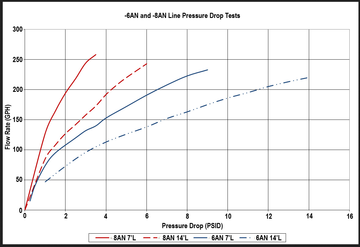
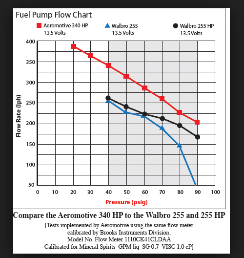
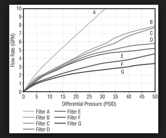
Mike, Don't think of "total head" as a change in elevation. It is the sum of all of the restrictions that impede flow. It is said and implied like that because that is the actual impact on the system, but the actual elevations don't need to look like that. There is elevation, (and what is fun is the fact that you "lift" the fuel to the pump, suction side restrictions can have a higher impact on system performance than discharge restrictions...) which is the elevation of the supply, elevation of the pump and elevation of the discharge. Now you add the restrictions (pressure drops) of fuel flow in the hose, what the surface roughness of the hose is, the fittings. The elbows in the system, then the biggies, like pressure regulators and filters. (and valves.... valves can be real resource hogs) Here is a representative of pressure loss in hoses. (-6 is 3/8 and -8 is 1/2) That is for straight lines, not bent. Elbows (depending on internal design and radius) can add about 30 times the restriction of 1 foot of pipe/hose. (banjos are usually worse) Here is a generic pressure drop vs flow rate for filters. Viscosity makes a huge difference, but this gives you an idea, the more you try to flow through the filter, the more pressure drop (head) it adds to the system. These charts are for clean filters. Start to imagine what happens as they get dirty. Here is a great graph (sorry it is for Fuel injected gas vehicles,) but look how fast head and flow change positions.... even with a good pump.... Notice flow rate is in litres per hour Which is about .26 gph so the top of the flow is 100 gph. Hope the background gives you some visual of what is going on. HTH Hag
-
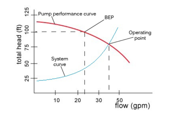
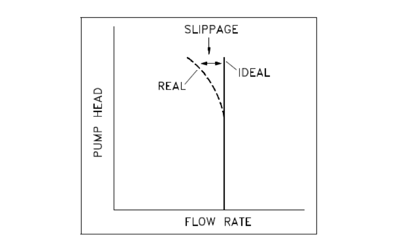
Here is a typical pump flow/head curve.... (flow is flow, head is the pressure working against the pump (whether on the inlet or outlet side...) (these are not the numbers we work with but 1psi is 2.3 ft of head ) Notice how for the pump to flow over 50gpm, it needs to see less than 50 ft of head resistance. But if we have 75 feet of head resistance, it will only flow about 40gpm. As we get closer to 112 ft of head (your filters are getting dirty....) and flow goes nearly to zero.... yes zero gpm it has stalled.... for sales sake we get a cherry picked number. If i was selling you this pump (and an advertising guy not an engineer) I would say it flows 50 gpm. I would say it can operate at 110ft head. I didn't lie, but I didn't tell you the complete truth. The gear rotor and vane type pumps we use fall under the "positive displacement" types, but they are far from positive displacement. So there is a flow/head curve associated with it. Here is the "curve" for positive displacement pumps..... It is unitless, but you get the idea. It will hold a flow rate for a set of conditions, but then migrates away from ideal, as the restriction to flow increases. This "slippage" can be internal recirculation of fluid, or speed of prime mover slowing, etc etc. HTH Hag
-
That is a normal way to show a shielded pair. With only one side going to ground. I'm not electrical, so my terminology may be a bit off, but the end not connected is "floated" and the other end of the shield is grounded. This was to prevent electromagnetic interference on the wires. (if you ground both ends....well this can set up a problem that ground loops and sends your signals haywire....ask me how I know....) just for fun, sometime you do connect both ends to ground though..... I swear sparky's used the English language as a guide to setup their rules for electricity. (the exceptions are almost as plentiful as the rules.... lol) Hag

