


Haggar
Unpaid Member
-
Joined
-
Last visited
Everything posted by Haggar
-
Aww we don't have the emojis for the "this thread is pointless without pics" Pics of the Riviera! Hag
-
I find it very hard to fully fill the coolant system on both dodges. The upper radiator hose is higher than the top of the radiator. I can usually squeeze the hose and suck a bit extra coolant in there, but I can't positively ensure all the air has escaped. Even when I use my funnel with the extension and radiator adapter, I don't feel like I have gotten all the air out. Part of me wants to make a bleeder in the upper radiator hose..... but then there are more hose clamps... Grrrrr Hag
-
Glad you are ok and you found it. I was hoping for a rear, it is cheaper to rebuild. But it is what it is. Hag
-
Soox, Too firm and almost firm etc etc are too subjective of statements. The reason the cap has a pressure setting is, its allowed to rise to that pressure and then be relieved, maintaining at or below that pressure. When we come to the hose, in theory you could determine the internal pressure by a deflection game on the exterior of the hose, but that information is not easily available, and would be different for each batch of hoses made... (what is the elastic properties of the reinforcing cloth etc.) You can do this for yourself if you are really interested. Get a pressure test rig for the radiator (this way you can put differing pressures in the system.) get a tool like a belt tension gauge that allows you to put the exact same amount of force repeatably. Get a tool to measure the deflection. (or a good reference on the engine if the tool has built in measurement.) Make a chart for deflection vs pressure. Now anytime you wanted to know the pressure, you could measure the deflection with the know force and voila you know the pressure. (or as you are using the pressure test rig, just feel your hose at different pressures. you may remember the feeling of the different pressures) The other thing, you could put a pressure gauge in. For testing purposes, just hook the pressure test rig up, and run the engine. As the pressure rises you can read it on the gauge. How much pressure should it have? (I can hear my friends in unison... The perfect engineering answer....) "Well, it depends." There are too many variables there is no way to know what it "should be". Has so many things to do with things that are totally not controlled (or specifically controlled individually, but only generally controlled as a unit). I bet if you watched the "operating pressure at a given coolant temp" of each vehicle as it left the assembly line, there could be as much as 10 psi difference. Most would probably be in a 5 psi group, only by accident would they be the same.... (mainly because they all got the exact same coolant mixture, it came out of the same rail car.) Slight difference in hose lengths, slight difference in fan blade angles, accidental blockages in radiator or other parts of cooling system. routing of hoses (is the heat shield in exactly the right/same spots.) dimensional differences in water pumps... the list is ENORMOUS. Be happy with. 1. when cold, hose is not pressurized. 2. when just started, the hose shouldn't immediately become pressurized. 3. when hot, the hose is firmer than it was when it was cold. 4. no loss of coolant. 5. (nice when it works properly) full cold radiator, when warm increases the level in the coolant tank, and when cools back down, pulls coolant sent to the tank back into the radiator. GL HTH Hag
-
Soox, TL:DR at bottom Think of it like this. When you start a cold engine, there is lets say 6 gallons (notice the measurement is a volume) of coolant in the system. All of this coolant is 60 degrees F. When it gets to 190 degrees F, it is 6.25 gallons of coolant. (the mass of coolant stayed the same but the volume increased.) If our coolant system was just open to the atmosphere, you would push out the 1/4 gallon. Our system has a pressure cap. So the expansion of fluid is allowed to pressurize to a pressure, THEN it will allow some to spill to the reservoir. One thing to keep in mind, while the water temperature may be 190F, most of the surfaces inside the engine of the cooling system are much hotter than that. In fact many of the surfaces the coolant is touching are WAY above the boiling point of the coolant (if you are 50/50 it is about 225F with no pressure). The coolant in touch with a surface that has a temperature higher than 225F IMMEDIATELY BOILS, but then cools down quickly. This boiling will cause small bubbles in the coolant. This is bad, but unavoidable, for many reasons. The bubbles do not transfer heat well. the bubbles lead to cavitation in the pump etc. While the engine manufacturer cannot avoid the sudden bubble formation, through good design, they minimize the effects. High turbulent flow keeps the insulating bubbles from staying on the surface. turbulent flow causes the hot gas to cool and collapse, reforming into a liquid. A hot engine, turned off will form bubbles out the behind. There is now no flow to break them up and move them. (pop your belt off and run the water pump with a drill, bubble formation will be minimized.) To look at this at home, grab a pot and put some water in it. Throw it on the stove. Crank the stove eye to high. Watch the water. The very first thing you will see is the formation of bubble on the bottom surface. now stick your finger in the water (or stick a thermometer in it for weenies), is it boiling? no, its not close, but the water near the bottom of the pot is boiling, but the whole mass is not near boiling. now start stirring the water, are there more or less bubbles? Now as the whole mass of water begins to get hotter, more bubbles will form. Until we hit the point where it is at a "rolling boil". The "hard upper radiator hose is a head gasket leak" has a HUGE caveat. The engine must be cold. The hard hose should be noticed in the first less than a minute of running. (so basically that there is no way that expanding coolant can create the pressure.) As many head gaskets (and cracked heads) as I have replaced, I can only think of one case where you may have noticed a hard hose during cranking... but the other signs were still huge and more obvious. When they catch the bubbles in a cooling system shooting for a head or head gasket diagnosis, they capture the expanding gas and test it for byproducts of combustion, (probably carbon monoxide, or carbon dioxide) otherwise they couldn't tell the difference between natural formation of bubbles from head/head gasket problems. Now when our cooling system cools down, If the radiator cap operates properly, the coolant goes from 6.25 gallons back to 6 gallons. This cooling creates a negative pressure, and "sucks" the coolant back from the coolant reservoir back into the radiator. ( ambient air pressure is greater than the pressure in the coolant system due to the reducing volume, and the coolant is pushed back in....) TL:DR probably nothing wrong. but keep an eye on it. HTH Hag
-
Double check your logic theory. Go get the PCM to command the Clutch coil to pull in it will need 2 things. The command from the heater control on the light green/ white. AND It will also need a 12v input coming into the PCM on the brown wire confirming that the high pressure AND low pressure switches are closed. I think that is your problem. Put the system back together and just put jumpers in both the high and low pressure switches. If it works, one of the switches are bad. I am pretty sure both switches are hot swappable. HTH Hag
-
Hit, Glad you finally got something! Its crazy when it just won't work, but there is no direction to help you figure it out! Hag
-
Cam, Order of replacement sounds correct. Before you start, MAKE SURE that the control arms have the correct bushings in them. My 2001 used 16mm bolts on the lower control arms and 14mm on the upper control arms. My guess is somewhere in 2000/2001 they upgraded the lower control arm bolts. A LOT of the replacement lower control arms only have 14mm bushing in them.... (that probably covers more of the total vehicles.) Just check your existing bolts on your truck with some dial calipers. make sure all your fasteners and bushings etc match. Good Luck! Hag
-
Thanks for sharing the pics!! What battery post adapters are those? I like them. The tinfoil thing was a "repair" they tried for the automatics to quit the "surging" (TC lock/unlock) that was being experienced about 10 to 12 years ago. Hag
-
Wow, That is spooky! Glad you are OK. It is a tough call. I would check differential first. It would be easy for one little piece to be wrong (broken tooth, Spider gear axle retaining bolt, etc) to get in the wrong place at the wrong time and lock it up. then reversing the mechanical action allows the offending piece to fall away, and all feel normal. I can't believe you are not 4wd. The chain wadding up is usually the culprit. So you have that going for you. It has to be something with the carrier in the rear diff. so between ring gear and pinion, or inside the spiders. Otherwise it is in the tranny. Good call by NIsaacs on pulling covers and looking for a tooth. GL! Hag
-
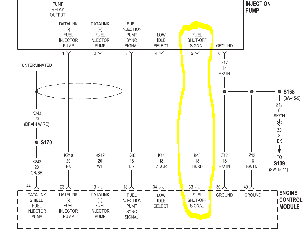
Thanks IBM, you are right. I misread or just didn't catch you were watching the fuel shutdown solenoid, I envisioned it as the fuel pump solenoid (or relay) hmmmm, That is interesting... I realized why I don't like your graphs.... notice they are all low while running, and spike high. That is exactly opposite to how either of those circuits should work. (fuel cutoff solenoids are always held open by power, so they close on loss of power. (same with the fuel pump solenoid. power holds it energized.) I think the same sampling error could be the problem... we are seeing the software command, but the output is latched. (though that doesn't explain the inversion) I want to think of the FSO to be digital like it is in a Ppump (and most other diesels). It is commanded high to (open and) allow run, removing power allows it to close and stop the fuel flow and therefor the run. Could Cummins/Bosche have decided to modulate this command? (I don't think this would be a Chrysler thing, the Engine, ECM and Inj pump were supplied by Cummins as a functioning unit. My brain hurts. Hag
-
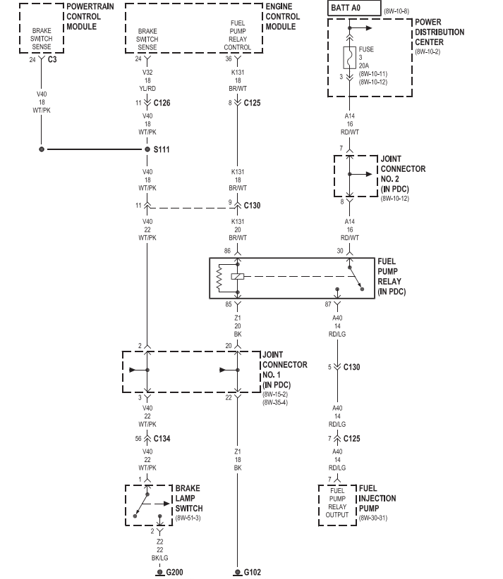
It (the fuel pump relay control you are scanning with the snap on) is what the ECM commands to turn on the DSG in the VP. It is what powers up our VP. We are seeing the software command for the output from the ECM terminal 36. The relay coil that it energizes completes the circuit for fuse 3 in the PDC (which is a constant hot, not interrupted by the ignition switch.) to the VP44 control circuit board. Thanks for reading it a couple times..... That is as simple as I could make it, but it is still a weird combination of words to describe. what is worse is my programming kung-fu is weak, so I may not use the correct words or current words for proper programming. Hag
-
I just had a brain fart. (gas gas gas) I think I feel better, and pretty sure I didn't get any on me.... I think I have a possible explanation, but your testing will confirm it. TL:DR go to bottom, otherwise we are heading into the rabbit hole.... We are displaying("seeing") the COMMAND from the ECM to the relay. What if the relay is internally latched through programming to stay energized until another condition is met. If this were a PLC program in ladder logic, my line would have a string of conditions that had to be met for the first firing of the relay coil. BUT i can latch that output with another set of conditions before it will turn off . If we were watching the logic run we would never worry that the set of conditions to make that output high (coil energized) happened again. But IF we were watching this logic program run by looking at the output that commanded the rung to go high, WITHOUT respect that it was already high, we would see a "new" command to go high any time the conditions were right. TL:DR we are seeing the command. The command may be valid at multiple times during running... SPST switch for starting vs 3 wire start. It is a shot in the dark, but I can see that reverse engineering my PLC programming might work like that. HTH Hag
-
Grrr, You will have an ECM issue (you are now actually) in the future.... Just know that it will not start if the WTS light doesn't cycle properly. You need to go through the parasitic draw testing. It takes time, but do it. Amp meter between battery and truck then pulling fuses is faster than pulling each fuse and measuring amp between those terminals, but both will give you the same answer. You could find that fixing the draw fixes the WTS problem. It is possible. maybe 10%. Its possible that what is causing the draw caused the damage in the ECM 20%. the other 70% is that they have nothing to do with each other. These are not known percentages, just good guesses based on what could still be powered up and kill the battery in a week not overnight. GL HTH Hag
-
Yeah a regular voltmeter won't see it, too much averaging and balancing. you would have to use the oscilloscope function to watch directly at the relay coil for the ECM command. I suspect (truely hoping!!!) it is a false signal. Something dropping out in the interpretative software of the snap on that no one caught.... Very interesting none the less. Hag
-
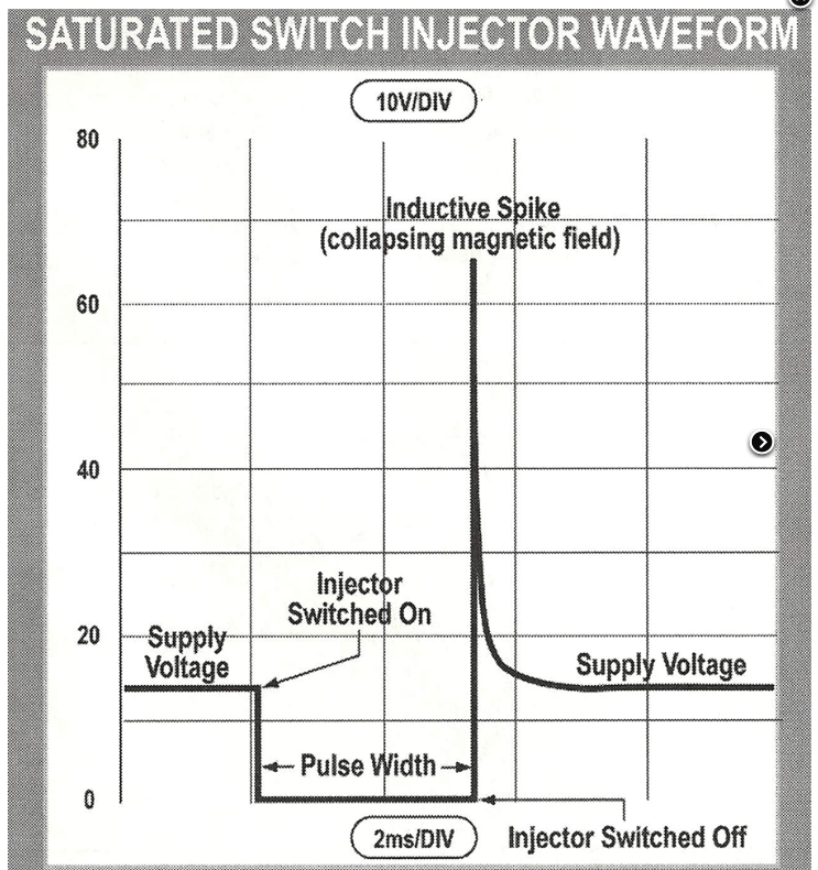
Moparman, We are seeing the theoretical command to the fuel pump relay. Agreed, if the command goes to off the truck will not run since that is the power to the VP PSG. Since this is the command to the relay and it is a very short spike the coil could keep the contacts closed (so truck does not shut off) and re-energize before the truck shut down.... BUT this has some huge and interesting implications..... If the coil is de-energized momentarily, there is a back EMF wave pushed towards the ECM..... This voltage spike can be quite tremendous. This picture is of an injector. But the concept is the same. When the command to the coil is interrupted, a spike of voltage is produced from the collapsing magnetic field..... (this is voltage, not necessarily amperage) so if we are worried about stray voltages damaging our ECM and if our programming actually turns this on and off (for no apparent reason) this stray voltage has to go somewhere, and back to the ECM it goes.... This is an ECM output, how does it handle a stray input... Probably not well. This shows an injector, the coil is being returned by fuel pressure and a spring, so the amplitude is higher than we might expect. But the similarity is there. It will be awesome to see if the signal is really there, or if it is a software interpretation. Hag
-
I wasn't worried about when it was down... It was the crunchy sound when I pulled it up.... The hydro boost limited the up travel when it was connected. Did I pull it up too far? That is my worry. I will know soon... Hag
-
When you turn on the key, and the wait to start light does NOT come on, do all the other lights come on? Are you getting a full response or partial response from the ignition switch? Since you have a battery drain, I wonder if the ignition switch is failing. As Dripley said, the wait to start light also confirms the boot up of the ECM. Sort your drain out first. The cause of it may also be the cause of the WTS problem. There are some good you tube videos of searching for a parasitic drain. The basic way is to put a amp meter between the battery and the battery lead. You will read an amperage if you have a problem. pull fuses until the problem goes away. We have 2 batteries so it is a bit weirder, but you can disconnect the passenger battery, but you have the alternator connected to that one. The alternator is a possible parasitic drain.(there should only be 2 wires to passenger battery, ALT leade and crossover to drivers battery. If there are more, someone added them and should be checked) If you don't find the circuit that is fused that reduces your amperage, it will be tough. That means that somehow some wire is attached to the batteries directly, but not fused in the panels. (there are two fuse panels one in cab and one underhood) Moparman and Dripley have referred you to a possible cause of the failed WTS. You will want to investigate it. But finding the drain is the biggest priority. (it could be both... if diodes are bad in the alternator you definitely made AC noise, and depending on the side of the bridge, can be a very large parasitic drain.) Good luck HTH Hag
-
Interesting.... @Dripley has my Solus. Maybe we can get him to look at the same parameter real time on his truck if he has it with him. The only thing I caution, we are watching the output of interpretative software.... It may not always be the real information. It is bits and bytes (pun intended) of the real info filtered through another software package. If you suspect it is real (boy it makes ZERO sense) do a measurement of the control wire to the fuel pump relay, does the command signal really fluctuate? In my small mind, I envision it does not. (that wire is going to be hard to back probe.... The ECM commands it. So one end is waaaay down there the other is buried under the PDC. you could use one of the relay jumper kits. or you can just hotwire 30 and 87 and test 86 to ground with high speed sampling. ) Good luck! This is very interesting. Hag
-
The input rod for the hydro boost is on a pin to the side of the brake pedal arm. The brake light switch is on a bracket sensing the front of the pedal arm. I do hope I didn't damage mine. after I got the hydro boost out I noticed my brake lights on. I am going like duh, there is nothing to push the pedal back to the rest position. I put a bungee on the brake and pulled it up. I hope I didn't pull it too far. Hag
-
As long as the main spring isn't damaged too bad (broken, cracked etc) they are adding the other leafs to support it. Put chocks on front wheels. Put the rear frame on jack stands with the axle in full droop, the tires just off the ground. set the parking brake or leave it set). lightly lift each side of the axle, undo your U bolts and let her sit on the ground. (watch your shocks, brake line, vent line or your rear sway bar may limit your travel.) do each side, then get the springs out. If you are worried about the travel, you can set the axle not on the ground but on another set of jack stands. (after you take the ubolts out, the block will come out, and you can actually go up with the rear differential and still have room to take springs out.) HTH Hag
-
Now that is a good question. I had the springs for the 64 Galaxy re-arched. (he kept main spring, and maybe some of the others, and added a couple) I had no clue then what I wanted, I just hated the droopy drawers look.... He asked me a bunch of questions, and then it was less than 200 for the pair (late 90s) and all the new u bolts etc.. I was totally impressed. I don't think you would want to do it to just one spring.... if he is good, he won't do one or at least advise you that trouble will surface... you will be leaning the other way... You need to talk to them. He should have already done something like this before and give you a real close price. If your main spring is good, the price should be reasonable. The spring with the eyes is expensive, all the others are just flat springs with a little arch in them. Hag
-
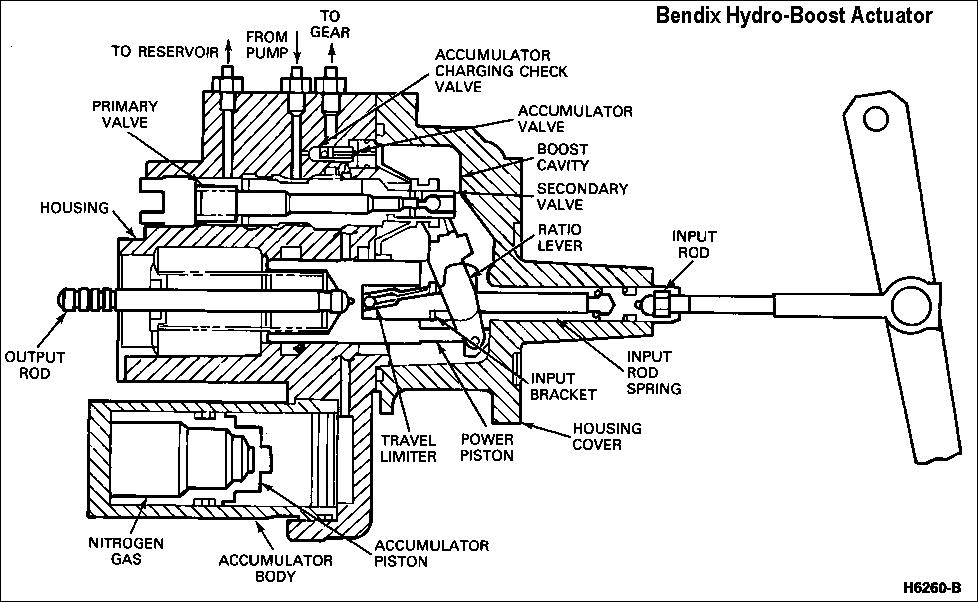
Soox, This is too funny.... I pulled my Hydroboost Saturday (and steering sector Sunday.....). Hope to have the kit here tomorrow. So I will try and take some pictures. I was not going to pull the rear seals you need to fix. (let a sleeping dog lie, lay whatever...) I will look and see..... The GM version used a staked actuator rod. Getting this apart is a bit of a pain. I will look and see if the Chrysler version is the same way. here is a generic cutaway. The "inner seals" are around part of the input rod. Notice the input rod "ring" that goes to the brake pedal is too big in diameter for the housing cover to come off over the "ring" so the input rod needs to be disassembled. Like I said, GM staked that together. We will see how Chrysler did. My leak is around the power piston. I hope the piston is in good shape and just needs a seal. Brake light switch is not affected during removal of hydroboost. I will update you guys soon. Hag
-
Do you have a truck/trailer spring shop near you? These guys are awesome to talk to, and will rebuild your leaf stack for you. They should be able to give you some great advice on where you want to go with the truck. took about a week, if you can live without the truck that long. If you can't, take them a junkyard set. GL HTH
-
I tried to find the article, but didn't find it quickly. Have a good DVM. Set to AC. put one probe on positive battery terminal and the other on the negative. You will see AC volts. This AC will change with how hard the alternator is charging and engine speed. So if you see bad numbers before you do anything, there is no reason to keep proving the problem. I couldn't find the exact numbers, but you are looking for found it it is in transmission section, not electrical. I think it should be cross posted..... HTH Hag

