


Haggar
Unpaid Member
-
Joined
-
Last visited
Everything posted by Haggar
-
Glad you found it!!!! None of my dodges have the steering wheel radio stuff. So did your aftermarket piece allow this use again? That is great if it did! Hag
-
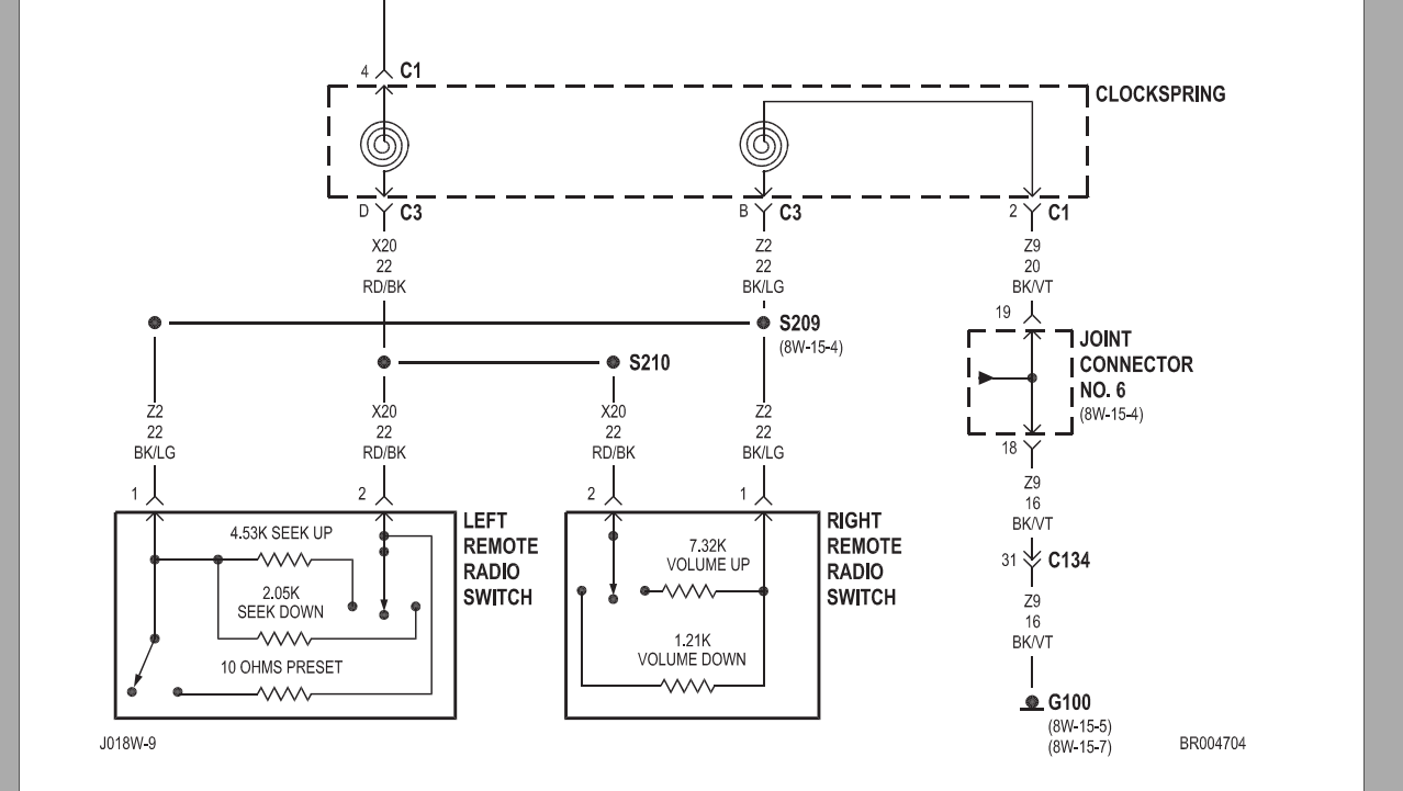
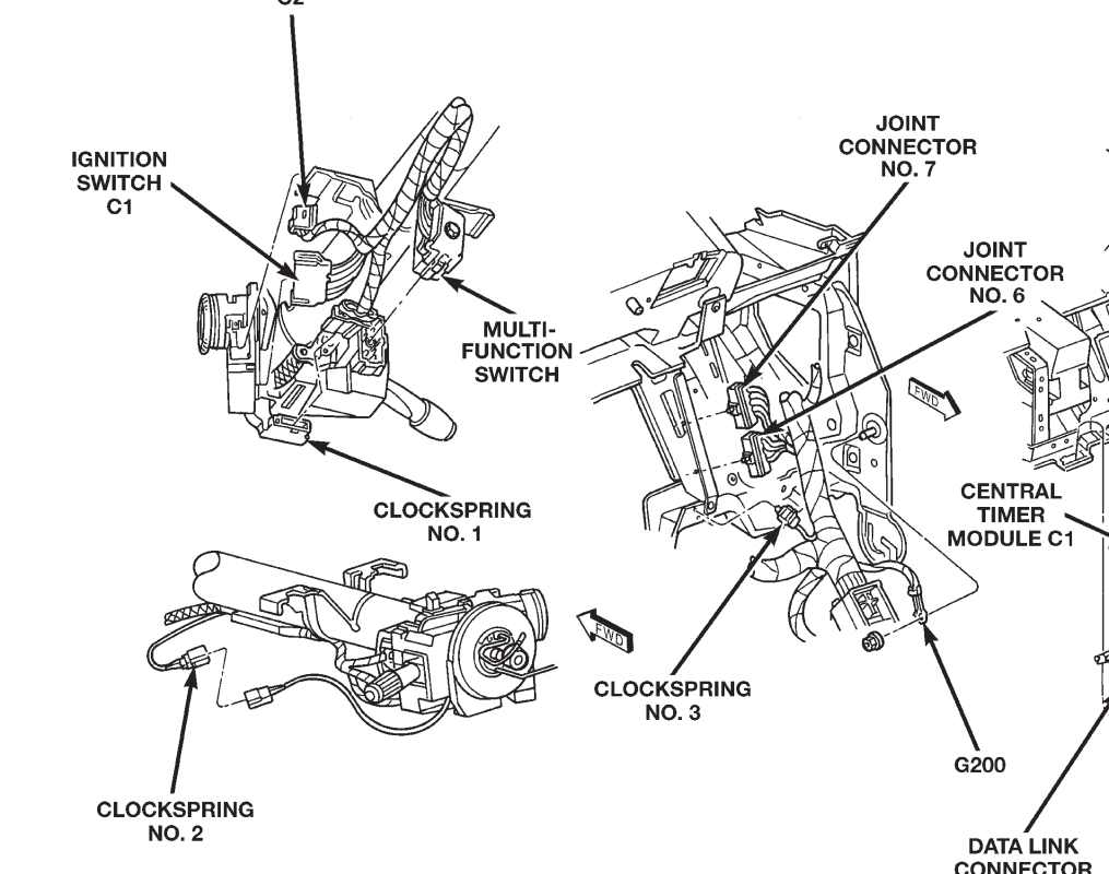
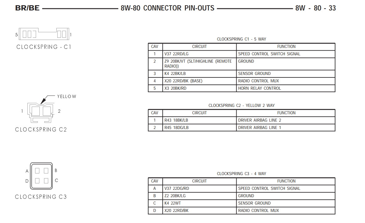
Connector C1 is after the clock spring, so that should be somewhere on the column. Clock spring 1 2 and 3 location Pinouts for each connector.
-
A trick i learned on these new packaged wheel bearings..... jack the car up and spin the wheel. Then loosen the nut that is setting the pre-load on the package bearing. now spin the wheel again. More than once when chasing a wheel bearing, the minute you spin the wheel when you just lifted it off the ground, it feels fine, but when you loosen the pre-load, it felt like snot. replace that bearing and its a happy sunny day! GL HTH Hag
-
The 2500 with automatic transmissions got the dana 70U rear differential. The 2500 with manual transmissions got the dana 80 all 3500 whether automatic or manual got the dana 80. hope that helps. Hag
-
As long as the relays stay in place, and you just unhook the main power lead, you will not show an error in the PCM. The computer is kinda stupid. It only checks that there is resistance in the control circuit. (that is how it knows there are relays there to be cycled.) It does not CONFIRM that power flows from the battery to the grid heaters. So basically, if you leave the relays in place, the computer thinks everything is kosher. It doesn't know you have it relaying nothing..... Hag
-
Greg, Sorry I have no insight for you.... I hope someone will chime in. I need to replace fenders on mine, so I want to see what you find. It will help me not make the same boo boo. But it sure sounds like something didn't get plugged in just right or you missed a ground.... Hag
-
There is also the lifter gallery plate and seal. It sounds like if you are doing the vp go ahead and replace that gasket at the same time. GL Hag
-
The ECM (from pin 36) controls the coil on the relay that provides power for pin 7. This is from a 2001 manual, but I suspect yours is similar. HTH Hag
-
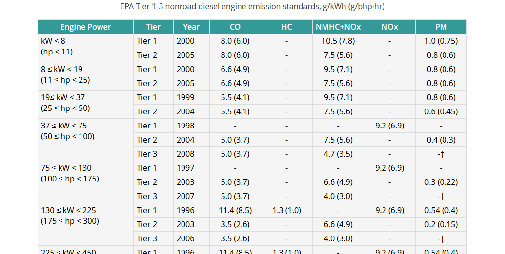
Jeep, Automobiles (on road vehicles) had to meet different EPA standards than off road vehicles or Tier 1 compliance. So you could tune completely differently. I don't remember how cam profile effects these numbers but I am sure that was used to make output changes also. Here are the numbers for Tier 1 "Light heavy duty onroad vehicles" Here is the table for off road engine tier 1

-
That's interesting. I will look up what the dimensions are, but we have an "odd shape" sensor like that in the US. It was an oil pressure sensor. I have a special socket from the late 1970's early 80's and that is what is stamped on the outside. Most domestic oil pressure sensors (GM,Ford, Chrysler) used that same sensor shape. But I know one of my import cars used the same thing... not sure if it was the Audi or the VW's.... man my memory sucks anymore... Hag
-
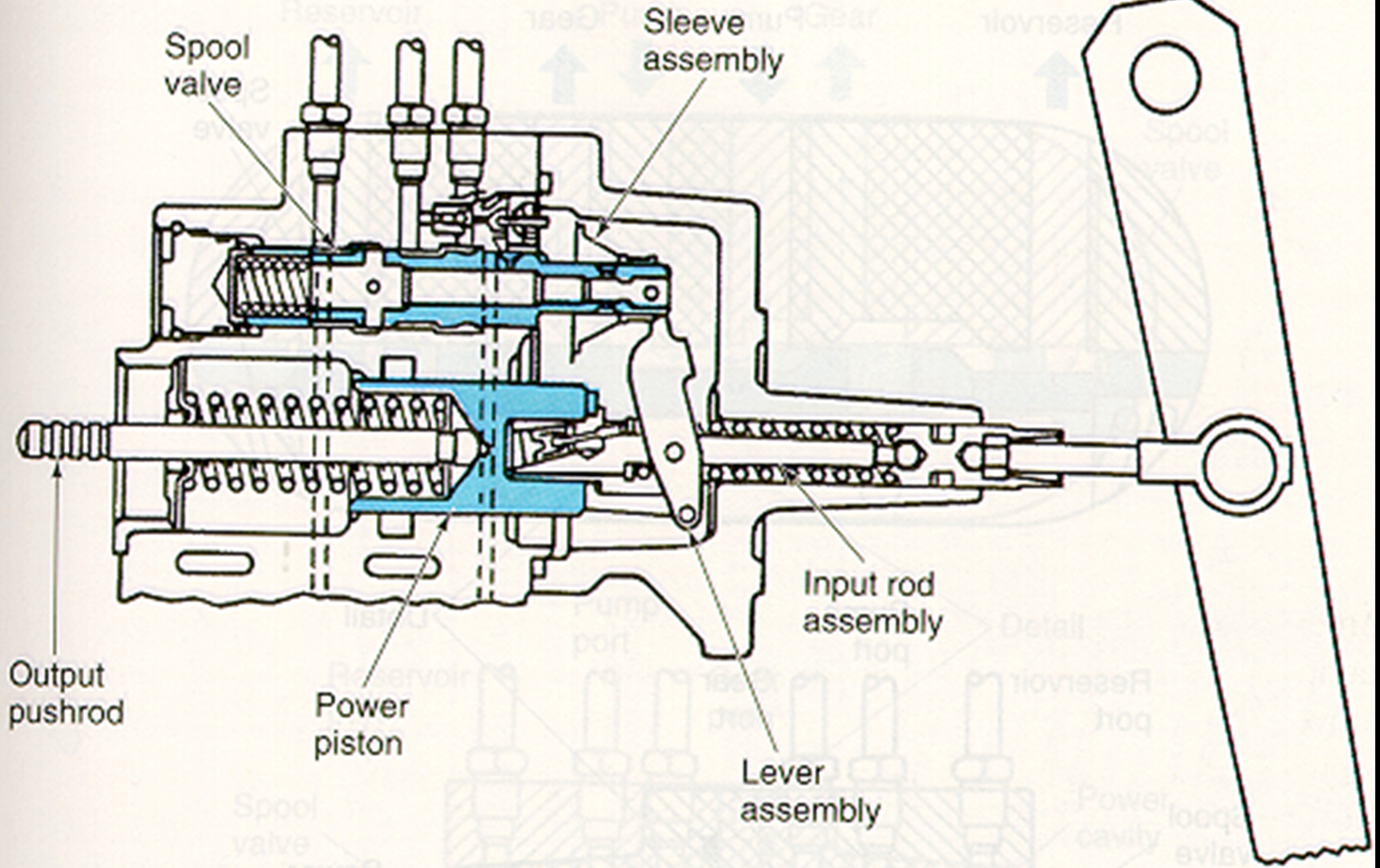
Taking some things for granted (the pressure side is connected correctly and not swapped with the return) It sounds like your input rod is too long, or the rear cover was removed and not reassembled properly, so the actuation lever is not in the correct position. (never take for granted the input rod is the correct length out of the box!!!!!) to determine if it is the input rod length, install it without connecting the input rod to the brake pedal. start the truck. The hydroboost should not go to full apply on its own. You can try to push the input rod to see if it actuates and moves properly when not connected to the brake pedal. GL Hag
-
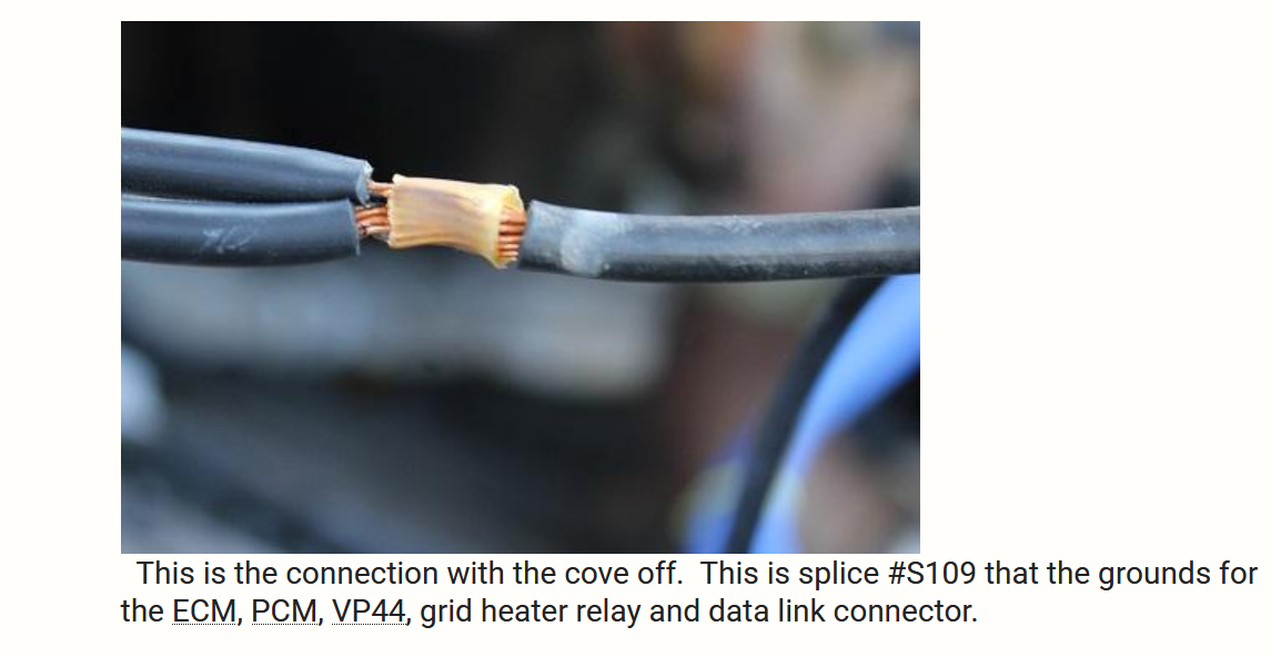
Brooks, If you have both connectors loose, and you are checking from one of the ground pins to ground, the resistance should be steady and nearly zero..... (you need both loose, so you are not also seeing resistance through the circuitry of the modules) 1.5ohm resistance in the grounding could be a HUGE problem. I stole this snip from IBMobile, but it will help you with the visualization of the splices.... notice the wires just lay together. there is no mechanical fastening of wire to wire. These splices can add resistance. S168 is probably the same way... his are very clean, but if oxidation has begun to grow in these areas, ghost systemic losses will appear.
-
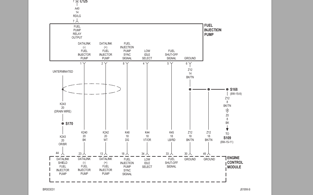
Brooks, Definitely recheck those using the black /tan wire connecting terminals 6 at the pump and 30 at the ECM as your ground. If you get a different reading than the open circuit you got during your initial test, then you can be sure that there is an issue in one of the two spices shown. You could do a quick test of the black/tan connecting 6 and 30 to the battery ground. That should be continuous with a real low resistance. If it is open or super high resistance it points to a splice issue. GL Hag
-
Double check your measurements, but I am seeing what you are saying. It looks like chrysler expected you to see some continuity from the data link wires to ground, not an open circuit. Did you measure it from terminal 6 or body ground? You may want to vary where you ground to see if you get any response.... (reason I say this, anywhere you see Sxxx connection is a splice. the wiring harness maker did not use the best method to make those splices) GL Hag
-
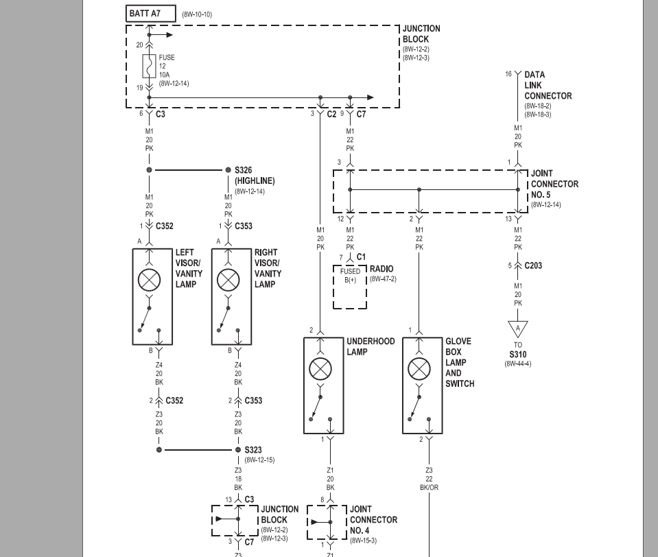
Here is the wiring for our trucks. This shows that it should be pink not orange, but orange was a typical hot leg color for interior lighting also. If you don't have wiring up there, you can tap into any of the other light hots. (glove box is probably easiest to get to. Notice it shows our drivers side should have a lighted visor even in the std model cab) GL HTH
-
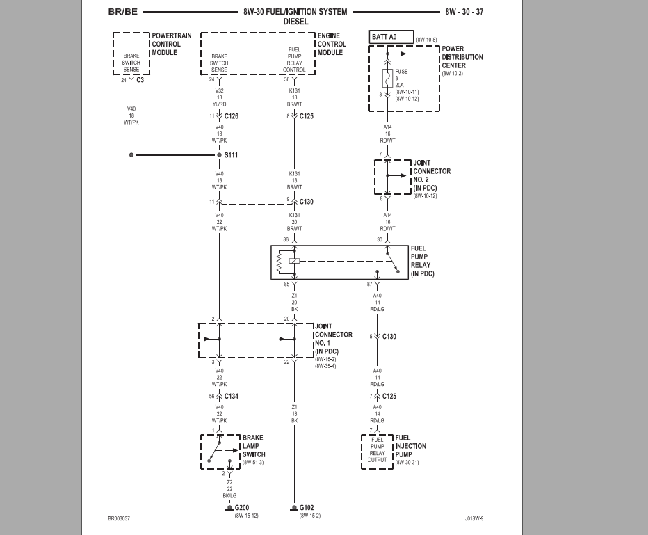
I found it in the ABS controller wiring too. It is not a speed signal. It is a brake sense. The ecm must want to know if you have the brake depressed. Looking at the section of the manual that refers to the ECM connections, pin 43 is never mentioned. See pages 8w-30-29 to 8w-30-42. on page 8w-30-37 a signal for brake sense comes in on pin 24. I never saw a wire labled going into the ECM on pin 43. I agree on 8w-80-40 the connector pin out for the ECM shows pin 43 as a vehicle speed signal, but none of the other wiring schematics show this at all. I think the connector pin out is incorrect on labeling pin 43. and since there is no wiring associated with it, I think it is empty or unused. I will try to look at mine soon. I need to pull the fuel manager and look for an oil leak. GL Hag
-
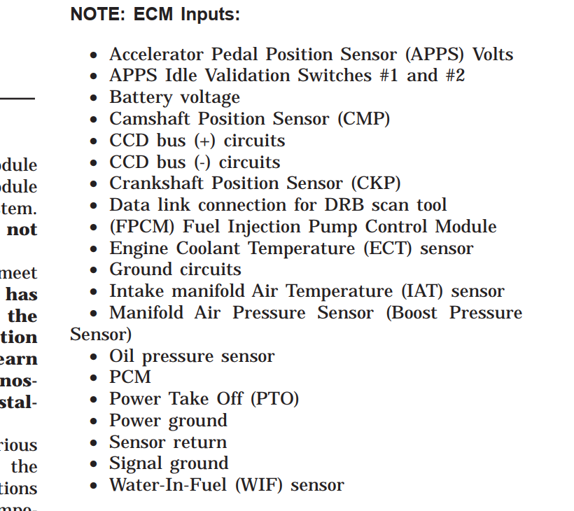
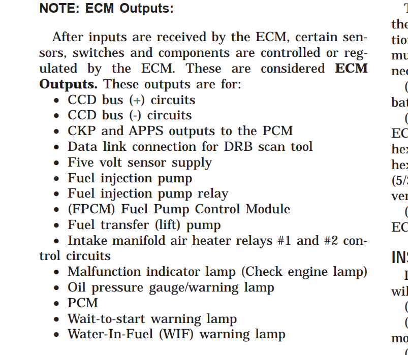
Interesting. I looked it up in the 2001 FSM. P0501 is not on the listed potential fault codes.... P0500 is on the list which is no vehicle speed detected. (so is that a FSM problem, or do you have a different PCM... interesting.) But for certain, don't spend time looking at the the ECM for this issue. The ECM cares not what the vehicle speed is. (I pasted the ECM inputs and outputs) Only the PCM and ABS care. Also with an automatic the PCM is resolving 2 "vehicle speed sensors".... One is the "output shaft speed sensor" and one is the "vehicle speed sensor" The Vehicle speed sensor is a tone ring on the final drive ring gear. It is usually used more for ABS and Speed display on the cluster. The output shaft speed sensor is located on the transmission somewhere. I assume that is the one you are having trouble with, since you still have speed display. Good luck. Hag
-
I swapped the ECM between my 2001.5 manual transmission, and my brother's 2001.5 automatic. It seemed to work fine. I did notice that the stall prevention on my brother's auto ECM was not as robust as my normal one. (the motor would not automatically respond or respond as quickly as mine.... I normally almost drop the clutch, no slipping to get started. I stalled his ECM with the manual a couple times. Other than that I saw zero difference. HTH Hag
-
bil, Across 85/86 the voltage should vary. During cranking it should be about 6v and running it should be 12v. You don't want that to die.... that is the signal for the fuel pump from your ECM. With the key on after 2 seconds or so, there should be no power there..... only during cranking, engine running, or the 25 second time during a crank with no start. HTH Hag
-
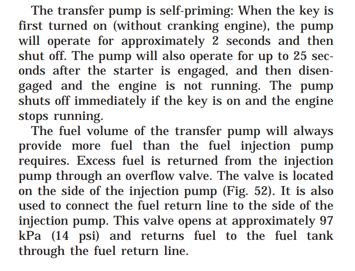
Your pump has been replaced. There should be a tattle tale tape saying warranty void if removed on the connector where I circled. Yours is missing. your warranty is void. I know my brother's 2001 had it. GL Hag
-
I have the same..... Truck didn't come with any of the jack tools. I use a a bolt with two bolts threaded together so i can use a socket and rachet. It's an odd size like 11/16ths or 13/16's or something, but I can't remember to save my life.... Hag
-
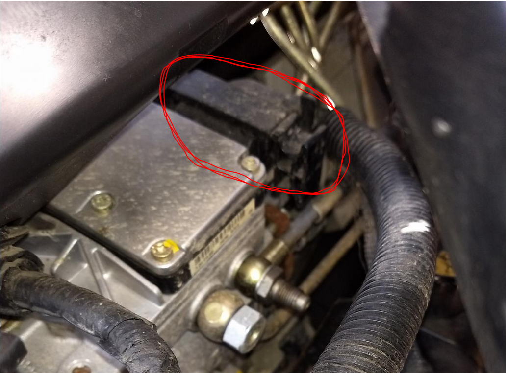
Double, There are 4 bolts from the top. I am betting what you see at the bottom are weld nuts on the winch assembly. GL Hag
-
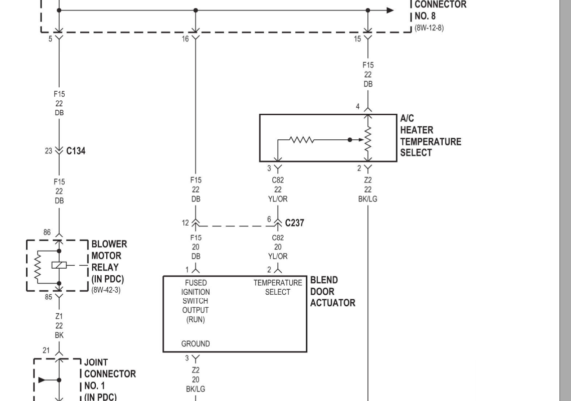
Dave, No not easily. I attached the wiring to the blend motor. (and put a snip here) You could check that the voltage varies on the yellow/orange relative to ground as you turn the knob from cold to hot. If it changes then you know that the command is being given. Checking for the response is a bit harder..... You could measure resistance from the Dark blue wire to the black light green wire to see if there is still a servo motor in between.... (if it were an open circuit you would know it is dead.) 2001 FSM Ram 8W-42-2.pdf
-
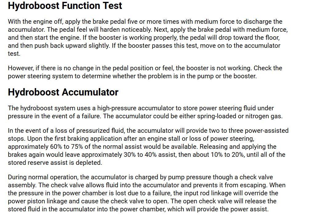
Mello, A brake pedal that slowly reaches the floor, is a brake system problem not a hydroboost problem. you could be losing brake fluid. (you should notice this in your reservoir) or You could be internally recirculating in the master cylinder. I attached the test procedure for the hydroboost below. GL HTH Hag
-
I would get yours rebuilt, or at least looked at. It worked wonderfully for 300k. so your gonna swap it with one from who knows where and someone you don't know said "they rebuilt it...." You may not have an alternator shop close, so the box store might be your only option. But if you have an alternator/starter shop I would trust them significantly more. Just my $0.02 GL Hag

