Jump to content
Mopar1973Man.Com LLC
  • Welcome To Mopar1973Man.Com LLC

    We are a privately owned support forum for the Dodge Ram Cummins Diesels. All information is free to read for everyone. To interact or ask questions you must have a subscription plan to enable all other features beyond reading. Please go over to the Subscription Page and pick out a plan that fits you best. At any time you wish to cancel the subscription please go back over to the Subscription Page and hit the Cancel button and your subscription will be stopped. All subscriptions are auto-renewing. 

DIY vp 44 and ECM. It runs, very happy


Recommended Posts

17 minutes ago, Mopar1973Man said:

I'm assuming this is the new ECM and VP44 controller you made? Wow. I wanna see the your hook up point how your wired in.

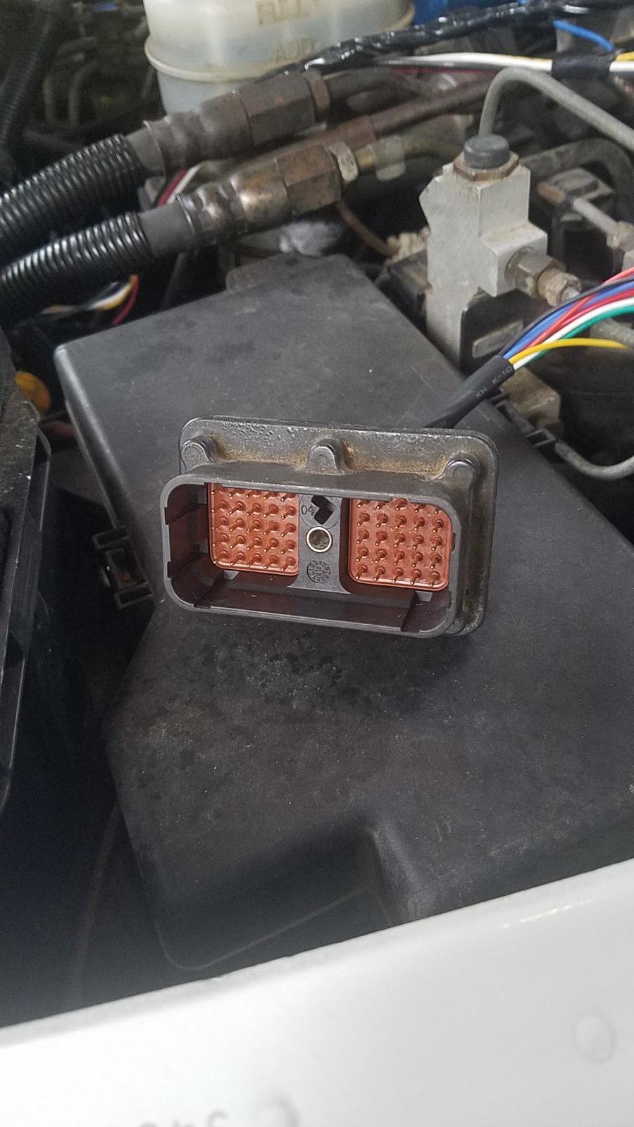
The hookup is pretty ugly right now. Since I had the ECM open anyway I soldered wires on the circuit board in there on the connector instead of hacking up the wire harness. I cut the wires from the psig to the solenoids and put quick connectors on. I also had to tap into the speed / angle sensor of the vp under it's cover. Tried to make a 5 min video on YouTube but I forgot to record it in low res so it was going to take hours to upload so I skipped it for now.

Link to comment
Share on other sites

  • Staff

Oh, it's only that it's very interesting that Great Work 'cracked the code', figured out a way around the factory ECM and PSU. If I'm grasping what you've done here... The failed VP isn't the timing piston failure but, is a fault with the psg on top of the vp and since the ECM also failed you have by passed both those two.


One thing... you young guys pick up on things fast, I need some of it sort of spelled out. Part of it also is the amazement when I see something like this.

Edited by JAG1
  • Like 1
Link to comment
Share on other sites

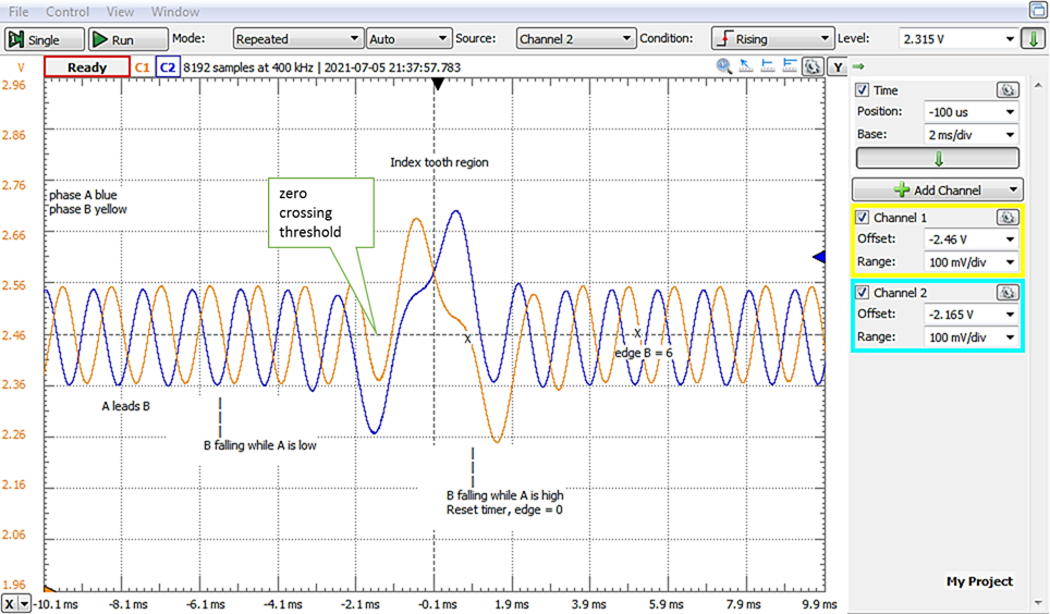
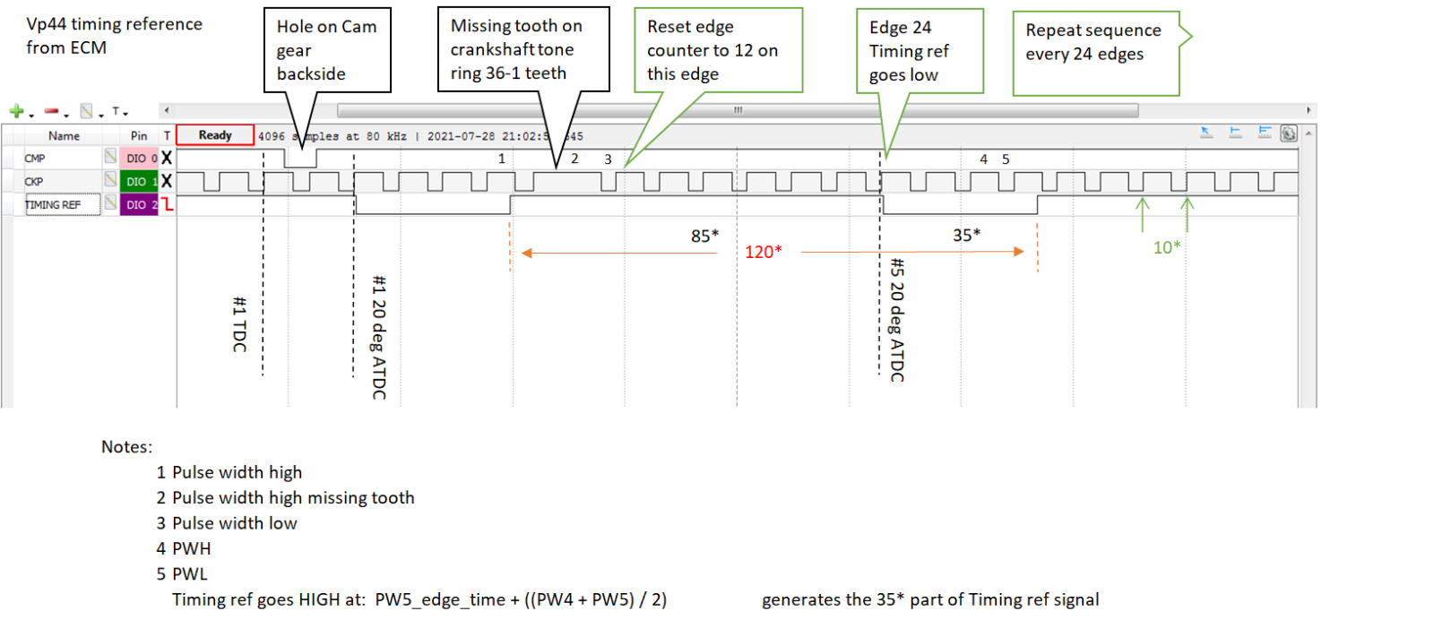
Main difference is there is no CAN bus. The tune / tables will be self contained and work off of TPS and MAP. So far I have 2 timing tables full load and no load indexed  by RPM. A value between full and no load is chosen by load or simply fuel quantity in a diesel engine no fuel to map table yet. Fuel is just what ever the TPS is. Other differences are the cam and crank sensors feed directly into it and are decoded into engine position without the ECM. A tach signal is output to the PCM to turn on the rest of the truck. There is still much to do. I need to translate the other sensors from voltage to temp and pressure and the convert that to CCD protocol then add a bus driver to the hardware so that the gauges work. Grid heaters are manual for now and lift pump power is tapped into the auto shutdown relay just like a gas truck for now.

  • Like 2
  • Thanks 1
Link to comment
Share on other sites

  • Owner
16 hours ago, Great work! said:

I need to translate the other sensors from voltage to temp


I can give a few values for temp. The IAT and ECT are the same resistor values at the same temp. As for oil pressure I know that with the CCD Network tool I've got from @Chris O.it does show correct pressure even though its a single wire sensor like the older Mopar's I use to work on. 


Need to create a out of zone error for all the sensors including APPS. Need to write the code so that if APPS falls out of range to set THROTTLE = ZERO. This way there is no runaways or out of control throttle. Then this takes you down writing the error code list and what ranges are normal and what is considered an error. Does it trip a CEL or just quietly store the code. Yeah I'd say there is more to go.

Edited by Mopar1973Man
Link to comment
Share on other sites

Update: hooked up APPS today and set some limits on that, made a better idle governor and improved the transition from idle to off the governor. Added a crude rev limiter and over speed shutdown today. Even with the WT-mod the sensors are very noisy. I tried smoothing the tps with software and hardware but to seriously reduce noise the throttle response gets a little slow. I'm going to try sampling the tps when both solenoids are off instead of randomly, the high current spikes seem to cause most of the noise. @Linuxpointed me to a method to chart temperature sensors  using 3 voltage vs temp reference points and the Steinhart - Hart equation. I also saw @Chris O.and Lorenzo's  github about CCD and I played around with it a couple years ago on a spare inst. Cluster. Definitely going to add some sanity checks as @Mopar1973Mansuggest. I actually had it idling at 575 RPM now I know why they idle at 800.

  • Like 1
Link to comment
Share on other sites

Not gonna lie i'm way out of my depth here electronics wise.. 


Is there any way to separate the tps signal? Maybe a shielded wire or something? 


This reminds me of a youtuber named Rob Dahm. He builds rotary mazdas including an awd billet 4 rotor rx7. He just rebuilt his wiring harness end to end for an aftermarket fuel injection system and power distribution module. One thing he continually stessed was how electrically sensitive they (rotaries) were. Crank angle sensor and fly by wire throttle bodies were all shielded twisted pair wires so the signal was as clean as possible.


Might be something to look into to clean up some of the electrical spikes.


Unless the dirty signal is coming from the board itself?


So i understand this, you essentially moved the fuel and timing from the factory ecu to the vp44 with what you created right? Or is it more like a Sniper/MoTeC/FiTech/FAST type ecu? 


The higer psi map sensor @Mopar1973Man mentioned would down the line if you decide to go to a boost reference fuel table similar to a Quad.. if thats possible with your setup..


I would be curious what you could get for rpms out of your setup. Sled puller in me that wants to see a vp44 do decently among the p pumps and efi live.. 


If there was a way to make a sniper type ecu out of this in the future, it could be the next big leap like the Quadzilla was with v2..

Link to comment
Share on other sites

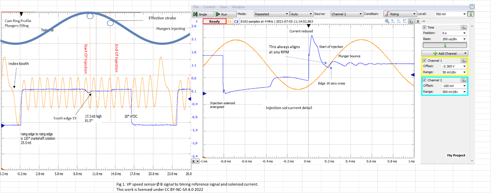
Originally this was going to replace the controller that sits on top of the pump. But when me ecm failed and I found out they aren't made anymore I just combined them.  It can do 45 deg of injection and 9 to 30 deg of timing. 40 deg of timing is possible with a shorter timing piston. I ran a simulation at 4000 rpm and that is asking alot of the inj sol. It only moves so fast kinda like valve float, and that's what will probably happen with my stock tired motor.

Link to comment
Share on other sites

4000 crank. The sol plunger has mass and inertia  so moving it (faithfully) at high speed requires a lot of electricity which makes for a very hot solenoid. 4000rpm = 200 hz or strokes per second for the plunger granted it moves slightly less then a millimeter it takes a lot. That's the drawback of rotary pumps.

Link to comment
Share on other sites

Good work.   very cool project.    If you want stock ecm maps I think I still have some of them mapped out someplace.  Might be a good place to start for building your maps.


Edited by Me78569
Link to comment
Share on other sites

  • Owner
On 3/28/2022 at 7:07 PM, Silverwolf2691 said:

Lighter material for the fuel pin?


I helped another person redesign the VP44 with the knowledge I have. After a lot of modifications, dual fuel feed into the body, higher internal regulator, drilled out some passages and few other mods. Stock SO pump typically tops at about 600 HP and his modified VP44 passed the 1,000 HP mark easy on the dyno. I don't remember part numbers or where he go the bits and pieces but it managed to do it. Pin would have to be magnetic too. So lighter alloys might not pull as good in the magnetic flux to open the pin. 

Link to comment
Share on other sites

I had some time to work on the truck tonight. Got the timing readings smoothed out and worked on the predictor algorithm some and got it running even smoother. I found it to be more tolerant in real world then in the lab I guess I was to picky. Next is cold starts I need that done before the weather gets any warmer. It likes to idle at about 10 BTDC warmed up but wants much more cold to clear up the exhaust. I need to drop it to about 5 deg for cranking in extreme cold. Then jump to 15 or more while warming up.

Link to comment
Share on other sites

×
×
  • Create New...