Jump to content
Posted

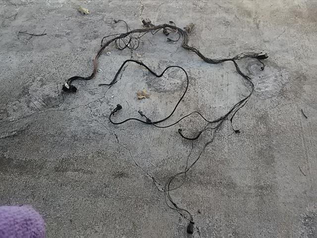
The truck I just got is on its 3rd alternator in a couple years according to previous owner, all have had diode failures causing the TC lock/unlock condition. Assuming that a quality high amp alternator is going to last longer than a over the counter replacement unit..


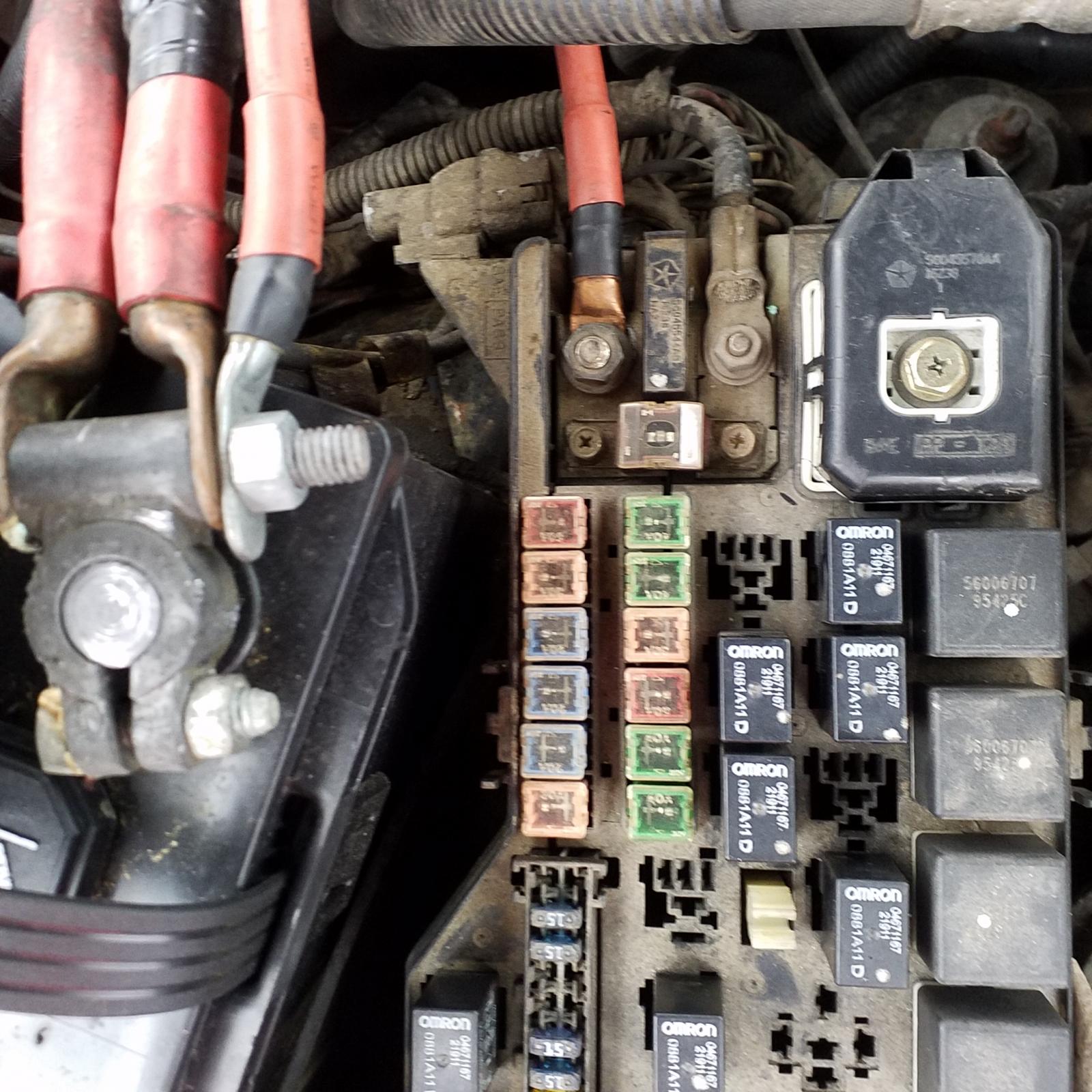
I was looking at nations alternators but the one for the 24v diesel looks to have a 2 pin plug on the back of it but mine has 2 ring terminal studs. Im new to dodge and cummins. What am I missing here? Does the 98 24v have one off parts or something??

  • Replies 217
  • Views 40.3k
  • Created
  • Last Reply

Top Posters In This Topic

Most Popular Posts

  • Mike is correct...the large current load on these 3 phase hairpin stators in conditions where all the available current is delivered does tax the design of the factory alternators. The diode's are all

  • I must admit there are many keen minds pondering this subject matter and I'm almost afraid to continue on this path but, nothing worth while is easy.   BTW...I'm still working so, when you n

  • @Dieselfuture Yes Sir, you are correct, multi pin weather-boot connectors should be dressed with Electronic Grade Silicon grease. It's a clean product and benefits small signal or low voltage contact

Posted Images

Featured Replies

I just had to do this...and I did expect to see this. Sorry for this size of the file Mike...I used my iPad on macro for close view. This IS the Master Ground (?) of the large conduit from the harness passing in front of the engine on it's way to the "three connectors" with the first at the battery tray on the passenger side.5a7beb5813ab3_Masterground4to1.jpg.706375b8724f08e1343c83a10acfaeab.jpgI did careful surgery here to peel back the high quality shrink tubing that was extremely difficult due to the seal/adhesive compound that was used to encapsulate this assembly prior to heat shrink application. NOTE: the four smaller black/tan ground wires are merely "stuffed" into the #8 Gage black/tan ground wire. NO CRIMP, NO SOLDER and NO TWIST...this is the factory assembly "glued together" and heat shrink to hide the sin. Mike...I think you told me this contains the primary ground for the VP44 electronics? None the less...this is NOT how to splice any wire(s) in any application. If this is a true identification of a VP44 lead that is supposed to be at ground, I'm very glad I took the time to inspect this. I will not take credit for this discovery as I did read about this on another web site. There was no photo so...here is my contribution.


This is NOT funny guys...when you discover how to access this mess for correction you will NOT be happy. 


I believe this electronic error to be as important as the "Killer Dowel Pin" for the second Gen CTD's. If you don't inspect this assembly and provide the service required, it would be highly questionable. 


Sorry to bare this bad news but, I've disassembled the entire electrical conduit assembly on the front of my engine...it's quite challenging. I am very confident in the worthiness of my efforts to eliminate the possibility of poor continuity.


I need some sleep...

Cheers      

Yea things are starting to become a bit cloudy. I think some actual mods to the trucks electrical setup with before and after of how the electrical behaved before versus after are what we need now. 


I have replaced aced all of my battery and ground cables with bigger and better quality stuff so I can help as needed, just let me know. 


If the grids really are what you think they are @Mopar1973Man then why not just change them out and find out for sure? 

Well I'm scared now I'm pulling my harness this weekend for sure I got a buss bad anyway but that that's not natural

  • Owner
2 hours ago, notlimah said:


If the grids really are what you think they are @Mopar1973Man then why not just change them out and find out for sure?


No way to measure the current grid heater draw nor measure the new grid heater draw. No way to even prove that is actually the problem as of yet. My Fluke 75 can only measure up to 20 Amp draw so I'm screwed for the moment. @outlaw7 just sent me a link to a China made gauge that measures 500 Amp well its a solution but let's see where my finances go this month maybe. 

That meter also comes in 750 and 1000 amp ranges as well I'm gonna work up a plug n play kit that is 52mm gauge pod based for ease of mounting 

  • Staff
8 hours ago, dave110 said:

You sure you can kick that high? He's like 7ft. tall from the picture I saw.

Sorry, I just had too. The Dave's gotta stick together!

I got all Dave's forming an alliance now :bolt:


I like what W-T has presented. The way he writes his post is excellent, educational,  wakes up even the foggiest morning.


I'm listening...  perhaps a good example, my headlights were not as bright as should be so even though the ground under the driver side kick panel still looked new, I took it apart sanded the mating surfaces. Interesting that under that kick panel is a painted surface and a crome plated ground terminal, I cleaned/ sanded everything in spite of the new look and the crome. It made a huge difference in my headlights. I was surprised.


Edited by JAG1

Good morning,

Guys...I do not wish to distort the desires of any technician that wishes to have an instrument for careful measurement of electrical parameters. The art of high current measurement is really very simple and inexpensive. All high current measurement is done with a 100 or 50 milliamp  meter. These are what Radio Shack sold for $4.98....NOW the key to using a little meter like this is to install a "high current shunt" in "series" with the high current line to be measured. You then connect the meter in "parallel" at the "shunt" connections. This photo shows the two screws where you make your meter connections.   tmc200-50.jpg.7e8e12c213075b86c8405978a4768d70.jpgThe major amount of electrons ( minus forces) race through the "shunt" unimpeded...the little side "pick off point" provides a calibrated amount of current to deflect your tiny mV (millivolt)  meter accurately. Calibrated "shunts" are available for $17 to $27 dollars...nice meters are $7 dollars. 


No one in their right mind would plump #0 Gage wire into their dashboards to read hundreds of "Amps":smart: on a meter face...that's insane ! Besides...every meter you view is a cheap little 50 or 100 mV (millivolt meter) shunted by a pricey calibrated shunt.


The photo depicts a 200 Amp shunt that would drive a little 50 mV meter to full deflection. The meter can be in a remote location for viewing and the "shunt" does the "grunt work" while you run a couple of #14 Gage tickle wires to the meter....simple...clean and safe.


Cheers,  


2.5 hours to remove it another hour to strip and clean it, it was nasty oil soaked and filthy . most of the flex and friction tape was garbage . IMG_20180208_114853.jpg.9e25c85013b80f832208aa7807b6a19e.jpg

the alternator feed cable is a joke for a 140 amp output unit so its going bye byeIMG_20180208_121949.jpg.57b5d9c7e58926ac1fc08d167ee62b4e.jpg

I have a spare harness I need to do this to. Bought it a while back and have not attempted to open much of it. Now all I need is some time. Aint getting much of that lately.

11 hours ago, JAG1 said:

I got all Dave's forming an alliance now

To be a D or not a D that is the question. l leave it to you. Ah ha haaaaaa!!


20 hours ago, Mopar1973Man said:


No way to measure the current grid heater draw nor measure the new grid heater draw. No way to even prove that is actually the problem as of yet. My Fluke 75 can only measure up to 20 Amp draw so I'm screwed for the moment. @outlaw7 just sent me a link to a China made gauge that measures 500 Amp well its a solution but let's see where my finances go this month maybe. 


Do you have to measure the amperage draw to determine if the units shot? I thought I remembered reading it was just checking resistance?


EDIT: found it http://dodgeram.org/tech/dsl/troubleshooting/Maniford_htr.htm

Edited by notlimah

Well I chased all my busses out last night right into the dash and I don't have a short or anything and it's starting to piss me off I've got 7 different cuts and gouges on my hands and arms , half my truck systems on the ground grrrrrr grrrrrr. Gotta work for a church this am then starting rewrapping the harnesses while integrating some extra features , gauge wiring and test points etc gonna be a long *** night I'll post pics as I go

  • Staff
13 hours ago, dripley said:

I have a spare harness I need to do this to. Bought it a while back and have not attempted to open much of it. Now all I need is some time. Aint getting much of that lately.

To be a D or not a D that is the question. l leave it to you. Ah ha haaaaaa!!


There is ......always will be just one Dripley in this world, Thank God :whistle2:

@outlaw7Wow...Garet, I'm not sure of the reason you have delved so profusely into removal of these multiple harness assemblies. I certainly applaud your diligence and if there is an error in your control or instrumentation then bravo to your detailed focus. 


This segment (page) of this running thread...I only wished to bring attention to the horrendous "sub-Master ground" regarding the black/tan #8 wire (previous photo) where four (smaller) black/tan wires are "poorly spliced" and my experience leads me to strongly suggest a correction of this particular ( and supposedly important) multi-lead ground. Your disassembly does cause me to pause and question the validity of your efforts?


None the less, since your "surgical" removal  of these harnesses.... I would like to call attention to an assembly nuance that may elude understanding and also possibly stop a fellow enthusiast from altering the assembly technique. 


I call your attention to this photo depicting the "water temperature sensor lead"...this particular lead is contained within the harness that runs across the front of the engine. Yes, I too am involved with disassembly of this harness but, not quite to the level Garet has taken this.IMG_0245.JPG.983abb934ac0a5e9adfd7794ac038689.JPGThe reason I wish to bring this to everyone's attention is because, this "pair" of sensor wires are "twisted" together. 


This sensor lead is only one pair of multiple leads within this rather larger harness... that IS "assembled" or "twisted" in this fashion. 


This harness also contains the #6 B+ charge wire that runs to the PDC (alternator Hot lead) and of course the "focus" #8 black/tan (sub-Master ground)  run returning to the passenger side negative battery terminal. 


I'm not trying to make a mountain out of a mole hill but, this "twisted" preparation of the water temperature sensor has meaning from an electrical stand point.


It is common practice in "point to point" wiring within chassis assemblies where multiple wire runs are are all confined to a particular location within the chassis confinement area. This holds true with "harness" assemblies that we see within our CTD's engine bay compartment. 


The practice of "twisting" a particular pair of wires in an assembly where "other" wires are in close proximity to one another is actually done to reject "interference" or "confine" the "electrical charge field" to the "twisted pair".  (am I killing you guys yet)?


Let me explain...this twisted-method is a poor mans way of providing isolation between "signal carrying" wires where the assembly has "no choice" of location.  


Any time you run two electrical wires that carry electrical charge in close proximity there is an "interaction" between the two wires due to the "EMF" electromagnetic force  or electromagnet "charge" of the near by wire(s)...this is a subtle but, a real phenomena that occasionally causes issues. 


Some of the wires in this particular harness are "low voltage/current" pairs, the B+ charge lead from the alternator to the PDC is a large current conductive element and of course the "messed up" multi-ground" black/tan #8 running "bass-akwards" is also in the mix. 


I found this interesting when I disassembled this harness to remove the B+ line ( my original focus) when I discovered this water-temp sensor lead to be "dressed out" in this fashion. 


I had to smile to myself with the fleeting thought, that Daimler/Chrysler might have a "real" Electronic Engineer on staff. (Just kidding...I'm being disrespectful)...they have such people. (my apologies) 


The art of "twisting" a pair is beneficial for "all confined" pairs. Any of you sporting "CB radios" ...the antenna line is "coax"... this is a self contained unbalanced "shielded" line. I am not suggesting that everyone tear the harnesses apart and install "coax" or shielded lines on every pair. This would be unthinkable.... I'm thinking of you Garet @outlaw7 :punish:(just funnin)...the use of "concentric line" known as coax today, is an ideal way of fully containing or promoting "isolation properties" of sensitive signal lines. 


We need not go overboard here...however; if a fellow enthusiast were to delve so deeply into a harness with multiple pairs and reassembly "allowed" such a procedure on any sensor line...then do so. 


By twisting standard insulated wires you are creating a self-protective phase reversal of the line itself...it has a natural physical property where an outside interfering "spike", "static", or "RF" (radio frequency) source is permeating the confined area where the wire runs lay. This is again the "poor mans" way of providing some isolation characteristics without busting the bank. Is it perfect....no, but, this method does provide a minor amount of "rejection" or "confinement" and is considered prudent. It is better than nothing! 


You needn't twist to tight...and depending on size (wire Gage) 5 or 6 turns per inch is ample. 


It is too bad that due to budget, during assembly, of the massive harness structures occupying the engine bay, that this old-school method was not implemented....or perhaps it was... when a "test scenario" was executed and the engineering staff suggested preparing the "water temperature sensor" lead to be subject?


I know from experience that running small signal lines near "massive" B+ lines" can create insidious consequences and logical "best practice" wiring geography is a must aspect to consider or....perhaps rethink?


I share this topic with respect to technical excellence and the development of a better understanding.


Cheers,    


  • Owner
8 minutes ago, W-T said:

By twisting standard insulated wires you are creating a self-protective phase reversal of the line itself...it has a natural physical property where an outside interfering "spike", "static", or "RF" (radio frequency) source is permeating the confined area where the wire runs lay. This is again the "poor mans" way of providing some isolation characteristics without busting the bank. Is it perfect....no, but, this method does provide a minor amount of "rejection" or "confinement" and is considered prudent. It is better than nothing! 


Bring out a bit more the design was to have mirror pulses. On one wire there is a positive pulse and then on the other wire there is negative pulse as long as both pulses are seen then the computer assume the signal is valid. So if noise is introduced to one side and another pulse is added there is no mirror pulse so the computers disregard that pulse as being valid. This system runs nearly the same rules as CAT5 cabling for networks.

12 minutes ago, W-T said:

am I killing you guys yet

Not yet but you may have wounded a few, lol.

I am looking for the MASH unit my self. 


This makes me wonder if somehow this might be the reason for the crazy temp swings my gauge experiences. They started about 10 years and continue today. I also developed an engine surgeabout 3 years that a new apps sensor did cure. This was accompanied with apps codes and an occasional map code. So one day i was going to put my spare map sensor in. During that process I broke the replacement and re installed the old. It has not surged since and the temp worked perfect for a couples  then went back to its old swing self. It seems my issues kind of wander around.

I am not trying to turn this into a solving my problem thread. That ismfor another thread. I have mostly thought my issues are electronic in nature rather than mechanical.

Edited by dripley

@dripley Good evening Sir...I certainly hope I'm not becoming a major annoyance on this site...I'm here for the brotherhood of Cummins Turbo Diesel enthusiasts :)


I understand your concerns...may I suggest in your service disciplines that grounds should be a first step...I know I sound like beating a dead horse here but, it's extremely important. Secondly, any time the service requires removing a "connector" whether it's under the dash or in the engine bay sometimes just the action of unplugging and reconnecting does some good but, for outright service a shot of Kegg product is real magic.IMG_0218.JPG.5f8a64b878c35515f47e61f9c16b44ab.JPGThis is the only product I use on large connectors or delicate component service. It is not "just another ******" product. Chemically this product is the only stuff NASA and high end manufacturers utilize as a standard. It will actually enhance connections. I use it sparingly and any connector I remove for any reason gets an injection of this liquid. 


Over time compounds in dust and airborne matter eventually causes errors on small signal contact points...the electrical flow on telemetry devices is extremely small and any debris at the contact points can cause erratic or unreliable, intermittent  readings. 


This product is produced by Kegg Industries and is available through several suppliers...I obtain mine from Mouser Electronics or Digi Key...only high end electronic facilities would have this....Oh...I forgot, Fry's electronics,would have this. It's a bit pricey but, used correctly a can like this will last years. This can is 3 years old and I still have 1/3 fill available. BTW the push button top control, has adjustable flow control for frugality.


I too do not wish to get started off subject but, I do not have lead acid batteries under the hood of my truck. I use AGM platforms only and avoid the gassing effect. Vehicles at ten years of age who have lived with a fart-cloud of sulfuric acid fumes under the hood require high-end maintenance disciplines to alleviate the unseen cancer of electronic corrosion.  


Sorry...I didn't wish to go off the rails here...lead acid batteries and Fred Flintstone cars get along quite well.:whistle2:   


4 minutes ago, W-T said:

@dripley Good evening Sir...I certainly hope I'm not becoming a major annoyance on this site...I'm here for the brotherhood of Cummins Turbo Diesel enthusiasts

No annoyance for me at all. I am here for the same reason. I have tackled a lot projects on my truck I would not have had it not been for the folks here, I have been reading this thread with great interest, the electrical part is definitely my weak point. So I will keep reading and hopefully gain a little more confidence along with it.

ok folks here it goes....... I found 2 grounds like w-t displayed, including one at the bottom of the ecm that had four 14awg tieed to a 10 awg that deadheads beside the starter on the block the fuel pump +12v is done this way as well as a couple buss sets and and a power set and I redid them all , I removed that big clump of orange wire that was like an extra foot and a half of uselessness, everything was fluxed soldered and heat shrunk to ease my mind.... and that's just the lower engine harness....the upper has only a couple done that way but both are bussing 2 for the +/- buss and two for the can buss protocol . yeah it was a lot of fun best part is I did not repeat not have a single short anywhere anywhen started get kinda pissy at that point. was cruising the web about my dash no bus condition and found two neat things number one is you can initiate a gauge cluster self test by holding in the trip reset and turning key to on position no start then releasing it and it will give you itws own trouble codes and everything....very cool.... and two again whilst bewildered scared and alone I found a true nugget that might save my sorry ***. guy claimed to have same symptoms I do werird codes no pcm coms no buss and dead pedaling issues that act strange he was checking connections and found his power distribution block harness connector ( the one that ties the engine harness to the firewall and power etc ) was NOT ONLY LOSE BUT NASTY HER CLEANED IT UP AND TIGHTENED IT AND BYE BYE CODES AND PROBLEMS ...WELL JUST SO HAPPENS WHEN I WENT TO YANK MINE OFF THE DAM BOLT SPUN FREELY IN MY FINGERS sorry caps lock bomb.... and as an added bonus got the green grimey goo not much but enough and it just happens to be on the buss side on the buss pins and connectors so I am going to walworld for contact cleaner cant get that keg deoxit W-T has so poor boys poor ways ive been gently scarping the female pins to clean them and then back to step hmmmm 8


so this is everything ive done all mods included

step 1 remove lower engine harness, better bring your patience meter and some Tylenol 6 big pain in the keister

          had only two casualties 1 is my lo side ac sensor it was melted to the connector so it got the loraina bobbit

          treatment. 2 the ground behind the starter bolt was froze solid its 10mm and I said $%^%#$%^ and lopped it off

          with a note to repair it

step 2 remove upper harness much mo easier guys, no problems at all

          total time for steps one and two 2.75 hours

          tools needed 10mm wrench and deep and shallows 1/4" drive , needle nose pliers flat blade screwdriver

          13mm 3/8" drive and long handle wratchet  side cutters and a I think 6mm allen wrench for the ecm connector

step 3 clean the harness I first sprayed it with brake kleen and wiped it down then a dose of acetone on a rag

step 4 strip the harnesses this was a lot of fun gently cutting and unwrapping everything and of course pictures for 

           refrence took 1 hour and needed two pairs needle nose to spread the harness clamps open and a set of

           front cuts for zipties and a small razor knife

step 5 reclean the harness cause it was nasty........... again acetone and a rag and patience lots of acetone and

           patience

step 6 using a copy of the 3 illistrations for the engine bay harness courtesy of mopar1973man which I spliced together with scissors and tape to make one large continuous map for ease of use I started ohming out every last dam thing total time 3 hours on harness one with notes and 2 hours on upper harness with notes

step 7 lower

          repairswhile I did not find any shorts I did feel the need to fix dodges sloppy handiwork so I repaired thw two

          ground points located just below the ecm split,  the fuel pump buss also below the split and added my custom

          fuel pump feed for my mid frame setup as well to the ground and fuel pump, the big mass of orange wire

          all tied together whicg there is 18" extra nopt needed that got shortened up its listed as a switch supply at the

          ecm I also repaired the ground mess further up near the alternator as well as another power related one

          red with white stripe that was done the same way.

          additions were as follows....a I taped a small blue wire on to the pump 12 v+ supply for the vp44

          which will go to the cab to a 12v led indicator for full time pump power notification and a orange 22awg wire

          to the apps sensor feed which again wikll go to the cab to a test banna point for quik check and monitor

          of my apps voltage via old skool analog meter these both have their own wetpack m/f connector at

          the point the lower ties into the upper and at the firewall where they leave going to the cab.

          upper

          the only repairs made were for the 2 can buss and the 2 buss points done the same way as the others solder

          and heat shrink, then I added my thermos couple feed for my gauge two 22 awg wires, 3 wires for my

          dc amps volts meter setup, 2 wires for the vp44 and apps test points and 4 wires 16awg for switching remotes

          on auxillary systems lights compressor etc, then I stripped and crimped all of my wet pack pins

          made an add on schematic for future refrence on pins and *** embled all my extra connectors together

step 8 tapeing every 8 to 10 " for ease in relooming then adding loom and then taping the harness front to back and at

           at all joints total time about 5 hours  tools solder iron solder sm phillips screwdriver all kinds of crimpers and

           strippers and other soldering based tools

step 9 ohm out new additions time 15 minutes

step 10 apply dielectric grease to all connectors everywhere and crimp on a new ring terminal for the ground

          by starter which I used 10b awg hi strand for that ground

step 11 reattach the harness clamps took about 10 minutes but set them loosely cause theygotta be movable

step 12 will be to install it


now I removed the alternator feed because it was whimpy and I'm wantin hefty plus I'm installing my ripple filter

beta test 001 for further evaluation . I'm installing 2 awg cable on its own route


so that's what ive done so far