

Alternator diode heat
- Replies 63
- Views 12.2k
- Created
- Last Reply
Top Posters In This Topic
-
Mopar1973Man 17 posts
-
dripley 10 posts
-
dave110 9 posts
-
2000Ram2500 8 posts


Most Popular Posts
-
I thought they stuffed chicken in a casket.
-
Just need brain food.
-
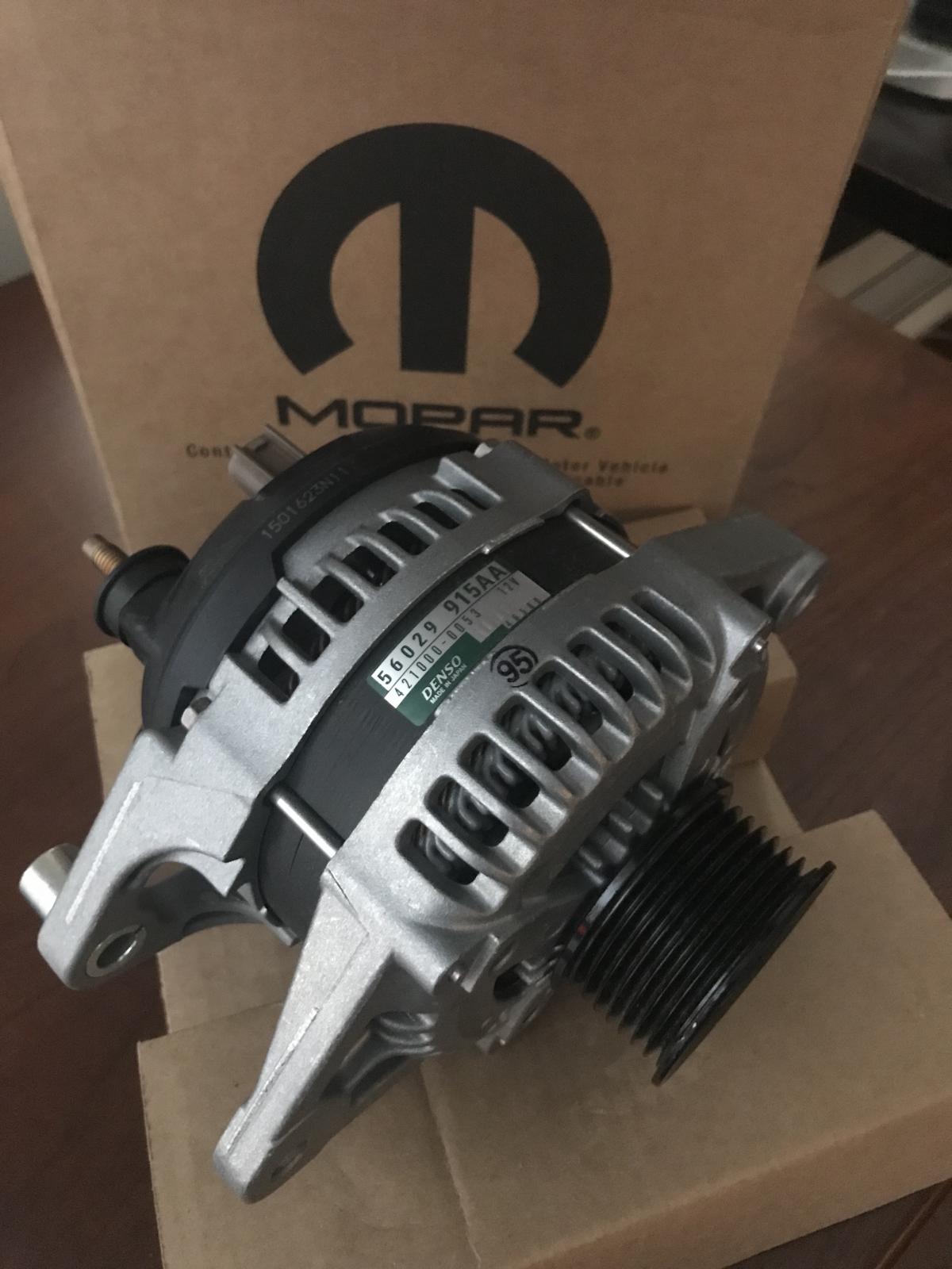
A cost effective way to get a better alternator with 12 diodes & a 6 phase stator is the 160amp "Police package" unit used on some early 2000's Durangos & LEO vehicles. You'll nee


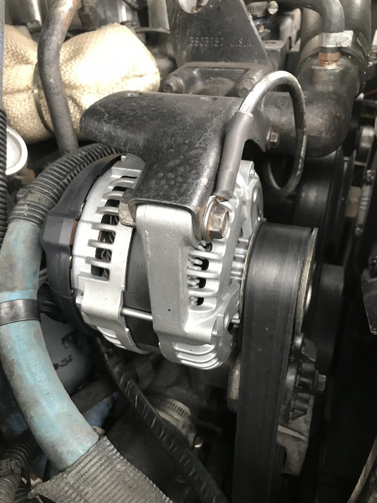
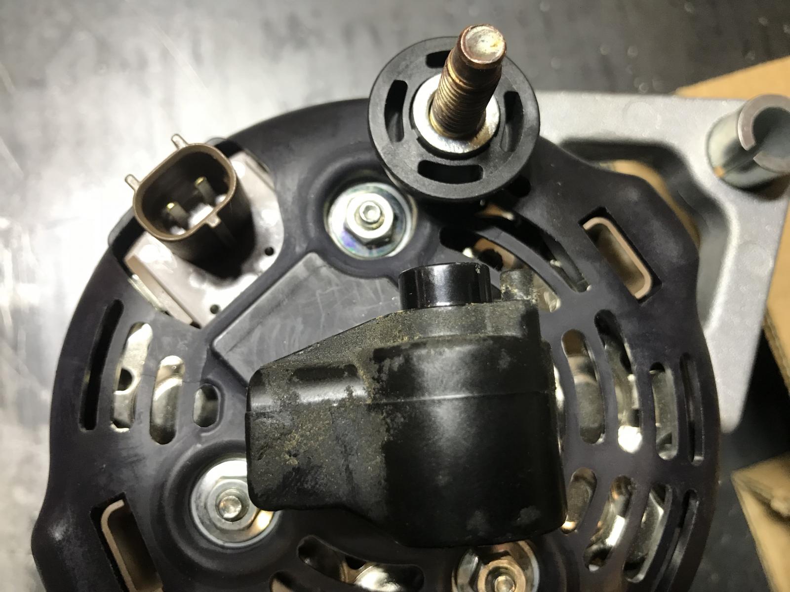

Something I figured out the other day. I had started my truck cold after doing a valve adjustment and the grid heater was cycling in and out as normal. Then I placed my hand on the back of the alternator near the diode plate and Wow! that thing gets hot. Even with the Quadzilla bumping up the idle to 1,200 RPM with its own high idle the draw of the grid heater is considerable.
I'm starting to think it might a be a good suggestion to replace my grid heater here in the future and see if the diode heat is reduced.