


Tractorman
Yearly Subscription
-
Joined
-
Last visited
Everything posted by Tractorman
-
I don't have a throttle switch or clutch switch with my exhaust brake setup and I use a momentary foot switch on the floor below the clutch pedal to operate the exhaust brake. I agree that you shouldn't use the exhaust brake and throttle at the same time, but for a different reason - that reason being that it would be possible to float the exhaust valves resulting in engine damage. How would EGT's "skyrocket" if you throttled while using the exhaust brake? I am not saying that it didn't happen to you - I am just trying to understand. In my thinking, the maximum air flow through the engine could only be what could pass through the orifice in the exhaust brake valve while it was closed. The turbocharger would not be able to spool up because the drive pressure on both sides of the turbine wheel would be virtually the same pressure. So in essence, the engine would be performing as a naturally aspirated engine with a severely restricted air flow. To support my theory, I took my truck for a test drive and attempted to accelerate with the exhaust brake actuated in fifth gear. Engine rpms peaked and stabilized at about 1700 rpm, boost remained at zero psi, and the EGT's peaked and stabilized at 800 degrees, and lots of black smoke poured out of the exhaust pipe. The zero psi boost, the 800 degree EGT, and the black smoke were about what I expected to see since there was not nearly enough air to burn the fuel to generate power or heat. - John
-
If it is a line connection at fault, you really can't blame the mechanic, especially if the lines have not been replaced for a long time. There are various size hoses and connections with plastic T's and fittings. The hoses get brittle or soft and crack or tear.. Carefully inspect each connection. The HVAC system will default to defrost mode if the vacuum supply is lost. This is designed for safety to ensure that the inside of the windshield will not fog. Let us know what you find. - John
-
It shouldn't for an oil and filter change, but you also said that he fuel filter was to be changed. That is in the area of vacuum lines. There are some large and small vacuum connections starting from the vacuum pump (large ones) up to the firewall near the rear of the valve cover. Any one of those connections could have been knocked loose or cracked - John
-
I use the throttle to match engine rpm to road speed (for a specific gear). The rpm matching must be done while the transmission is passing through neutral with the clutch engaged (foot off of the clutch pedal) When the road speed and engine rpm are matched, then quickly clutch and select the appropriate gear while holding the matching rpm with the throttle. This procedure works whether upshifting or downshifting. For example, when I prepare for a downshift, I start easing up on the throttle until the engine is unloaded in reference to the drive train. I then freeze the throttle position and select neutral without using the clutch pedal. The gear shifter slides easily into neutral because there is no torque on the gear. While the transmission is passing through neutral, I raise the engine rpm's to match the downshift gear speed (dictated by road speed) and again freeze the throttle position while clutching and slipping the transmission into gear, thus competing the downshift. The whole process actually happens q uickly and the results are smooth and seamless shifting. There is very little wear on the synchronizers or the pilot bearing because the transmission input shaft is rotating at engine speed ant the gear being selected will be matched to road speed. Back in the 70's, the truck driving school I attended taught the double clutching method, essentially the same as I explained above, but the first clutching would occur when pulling the transmission into neutral. The rest of the procedure was the same. One thing for sure, if the clutch is disengaged (pedal depressed) while the transmission is passing through neutral during a shift, the transmission input shaft speed will start slowing quickly and cannot be controlled with the throttle. Consequently, the synchronizer will have to do all of the work to match the gear to road speed. Also, since the engine and transmission input speeds will not be the same, unnecessary wear will be placed on the pilot bearing. During upshifts because the engine speed and the transmission input shaft speed fall off together naturally, the complete shift can be made with a single clutch while passing through neutral and timing the next gear selection. But, this procedure doesn't work for downshifting because the transmission input shaft must be engaged to the engine in order to raise the transmission input shaft speed for the downshift using the throttle. Hope this helps, - John
-
I think I can do that - give me a couple of days. - John
-
Mine is actually quieter than the factory air filter and box. If you end up doing the project, let us know what you think after you are done. Be sure to get an airtight seal between the parts. I think you will like the end results. Please resist the urge to glue feathers on the ribbed pipe - it won't make it any quieter and it might dust the turbo, you know, like a feather duster? - John
-
Sorry for the confusion. In a different post I had shown some photos of a silencer that I made for the inside of a BHAF. Dripley named it a BHAF muffler. I noticed in your video that I could hear the throaty sound of the intake part of the engine. The silencer that I made makes that sound go away - for me quieter is better.. I think the shortcut below will get you there. - John
-
Your truck needs my BHAF muffler kit. - John
-
But if you were and you leaned up against an electric fence, you might understand how back feeding could occur. - John
-
I agree with your above statement. The multi-meters that I use currently and in the past do not display a value lower than .1 ohm. Will your multi-meter display a value lower than .1 ohm, such as .01 ohm? If your meter is limited to measuring in tenths of an ohm (like mine), then theoretically the 95 amp element would be rounded down to .1 ohms. If your meter can measure in one-hundredths of an ohm, then the 95 amp element would be rounded to .13 which would be a value that you can work with. So, what I am trying to say is since the meters that I have worked with are limited to measuring within a tenth of an ohm, a .1 ohm reading could really be .08 ohms (150 amps), or .13 ohms (92.3 amps), for example. Since the meter would round these numbers to .1, one could draw an incorrect conclusion about how much actual amperage draw there is. This is why I don't use an ohmmeter to check for resistance on a high amperage circuit with the meters that I am familiar with. I still think that using a quality charging system tester with a clamp style ammeter would give you the most accurate intake heater current draw in a real-life situation and also tell you which heaters are operating after the engine is running during post heat cycles. Plus, you can check the output of the alternator during post heat cycles with or with out high idle. I apologize now if I have made this topic more confusing than it should be. - John
-
I don’t think that a resistance test on a high amperage circuit will have much value, primarily because the resistance changes greatly as the element is heated. Your test results kind of show that. For example, using Ohm’s Law based on your tests, the following results would be true if there is 12 volts available at the intake heater and the wiring is good condition: Cold intake heater at 12 volts / .1 ohm = 120 amps. (A bit high, but in the ballpark) Warm intake heater at 12 volts / .5 ohm = 24 amps. (I don’t think this is accurate) I think that a quality load tester with a clamp-on ammeter would get the results that you are looking for quickly. You could load test each intake heater circuit individually with the engine off, and then with the engine running. You could also test actual alternator output while grid heaters are cycling with or without high idle. I think using above test procedure would be very informative and you would quickly know whether or not the air intake heaters are performing as they should. This morning I performed a voltage drop test on the intake heater circuits. I prefer voltage drop tests over just inspecting electrical connections. Voltage drop tests tell you exactly what is going on with pinpoint accuracy because the test is being performed while the circuit is under its normal load. Many times I have seen what appears to be a clean and tight electrical connection, but the connection fails the voltage drop test because it is a dirty connection “electrically”. So, here is the information regarding my test. My truck is an ’02 with just over 300,000 miles on the original Bosch alternator. The intake heaters were modified to be operated manually by a momentary switch shortly after the truck was new. Since I only use the intake heaters when needed (never after engine is started), the alternator has had an easy life. At 215,000 miles as a maintenance procedure, I replaced only the brushes and bearings on the alternator. The current batteries in my truck are Group 24, 890 CCA @ 32*, 725 CCA @ 0*. The batteries are four months old. I manually performed two 10 second heat cycles with engine off, then three heat cycles with the engine running. I allowed a brief recharge time between cycles. I recorded the following readings in the last 5 seconds of the fourth and fifth heat cycle with engine running: Voltage drop = .6 volts from left positive battery post to each intake heater positive stud terminal. Voltage drop = 11.0 volts from each intake heater positive stud to common intake heater negative stud terminal. Voltage drop = .12 volts from common intake heater negative stud terminal to left negative battery post. The average battery voltage remained at about 11.7 volts during the last 5 seconds of each test. The sum of the voltage drops under load equals the average battery voltage under load within .02 of a volt. The .6 volt drop in the first test represents each fusible link in the positive side of the circuit, so this voltage drop is expected. The .12 volt drop in the third test represents a good ground circuit (should be under .2 volt drop.) The 11.0 volt drop in the second test represents the electrical load – the actual work being done. The voltage drop tests that I performed do not tell me the amperage draw of the intake heaters, but they do tell me that the condition of the wiring is good and the intake heaters are working. I only posted the voltage drop testing information because I think is the best method for maintaining good electrical connections before problems occur. One of the many benefits from using voltage drop testing is that any potential poor connection is never disturbed, but easily found during the test. Voltage drop testing is a very powerful diagnostic tool for determining the quality of electrical connections, but the procedure is probably the least used and the most misunderstood. - John
-
Ditto! After almost 5,000 miles of driving with the 245's with various combined loads of 12,500 lbs to 16,500 lbs making several trips to Baker City and back, there is no way I'm going back to a larger diameter tire. Some trips I used I-84, but most trips I used Hwy 26 with lots of mountain passes to climb and descend.. - John
-
Yes, the end of the perforated pipe is open and the opening is located about 2 inches from the inside of the blank end wall of the air filter. This project is one of the many small things that I have done to incrementally make the engine quieter. - John
-
Thanks for the comment - unfortunately, it was a long time ago (2001) when the running boards were purchased, so I don't recall the manufacturer. - John
-
I made my own silencer for the BHAF and now the BHAF is much quieter inside and outside of the cab than the factory air filter box and filter. I used a ribbed 3" perforated plastic drain pipe as the silencer. I modified a piece of my son-in-law's exhaust pipe from an '06 truck to make an airtight connection. I sealed the plastic pipe inside the modified exhaust pipe piece. The turbo whistle is completely gone now (the one sound I liked) and the exhaust brake is much quieter now. It is amazing how much sound is generated from the intake side of the engine. - John
.jpg.130cc6cc9a397b428c42aed90ede9dbd.jpg)
.jpg.b072b95b4171c54bbd27805251b8328e.jpg)
.jpg.6f58c827815b3e09a991c69208a3a7b2.jpg)
-
I watched your video - I think it's the oil cap that is making all the noise. - John
-
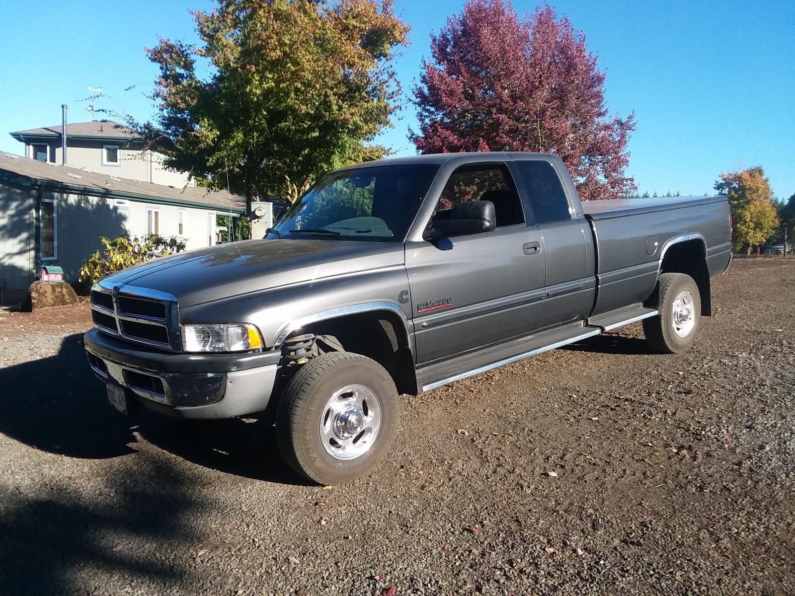
I've had these running boards on the truck since it was new. They have been reliable and are not very slippery when wet. They have never been exposed much to salty roads, so they remain in very good condition. The trim strips around the fenders are part of the package. - John
-
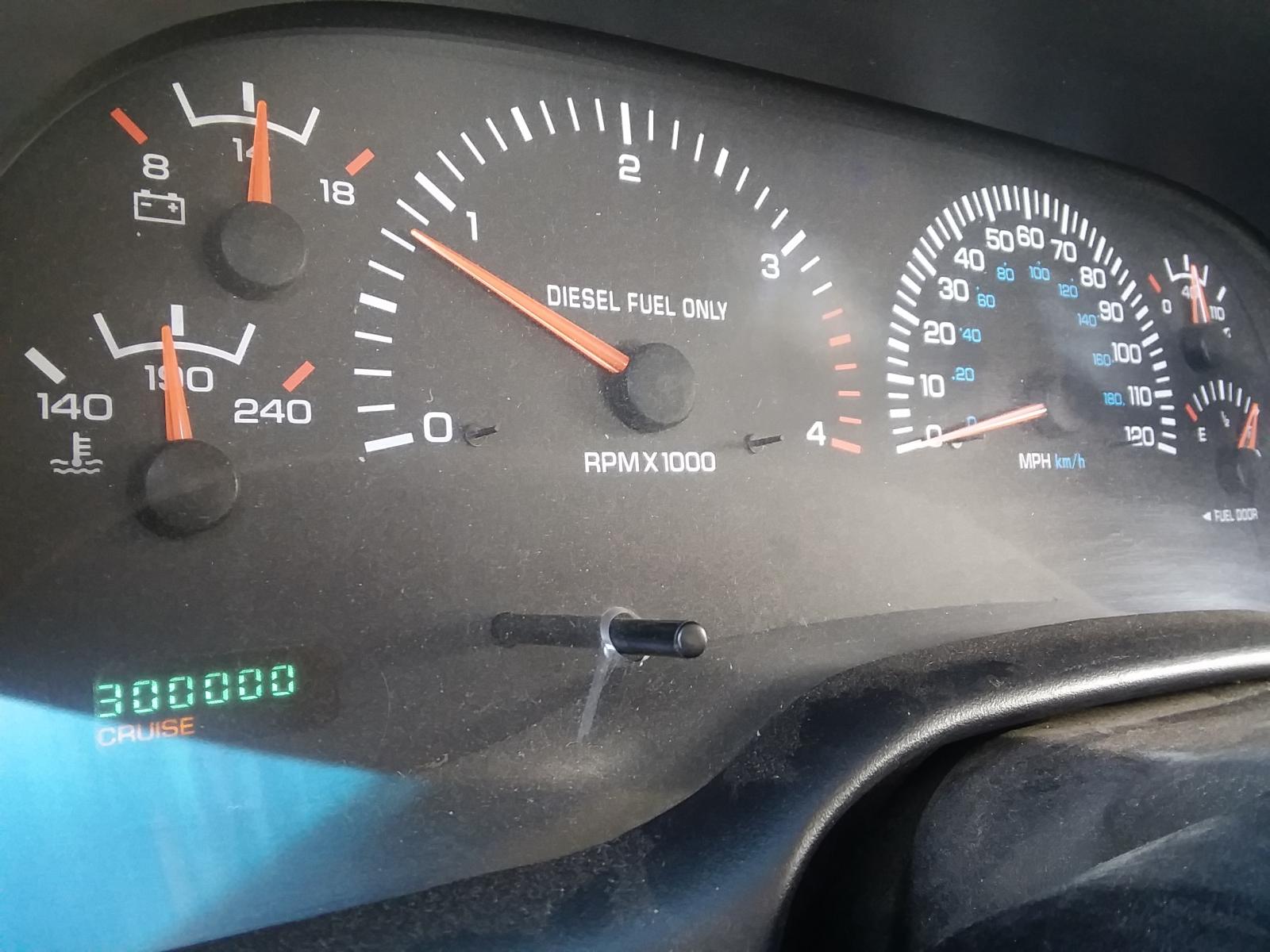
I also have a 2002 truck, but with a six speed transmission. I just crossed over the 300,000 mile mark last month and I intend to drive the truck at least to the 500,000 mile mark and then re-evaluate the truck condition. More than likely I will keep driving the truck past the 500,000 mile mark. Utilizing the extensive knowledge and personal experiences from participants of this website, I think you can drive a very reliable second generation truck for reasonable maintenance and repair costs for many years after 250,000 miles. Even at 300,000 miles my truck performs far better than it did the day I drove it off the lot. Maybe with high miles there is more risk for a breakdown, but it will likely be a breakdown where I can control costs because I know what I am capable of repairing. For me, I am comfortable with that. - John
-
I don't know about you guys... everyone knows these are spark plug boots. - John
-
Try lightly setting the park brake in very slippery situations. It is a poor man's solution for a limited slip, but it works when you need it - I know, I have done many times in snow country. - John
-
I don't think that the increased tire weight will be an issue. It's more about operating the engine in an RPM range that gives you performance and fuel economy. It is too bad that car and truck manufacturers don't provide engine performance charts that show engine horse power, engine torque, and fuel consumption in lbs/hp per hour at every RPM in its operating range. Years ago when I purchased a Cummins 4BTA 3.9 and installed it in a 1991 Ford F150, I was provided with this performance chart from Cummins. On that engine the peak torque was at 1700 RPM, but the lowest fuel consumption per hour was at 2100 RPM, so it gave me a good idea of what the final drive ratio should be. The Cummins engines in our 2nd generation trucks probably closely fit this performance chart. This is why the smaller tires will give a significant gain in fuel economy as well as performance Attached is a performance chart for a mid '80's 4BT3.9 (no aftercooler). Note the fuel consumption information (the horizontal line at the bottom of the graph) If you save the picture, you can zoom in on the graph for better detail. - John
.JPG.1e32ac54648bd4e6ea1b37a9b0219dc0.JPG)
-
I have just crossed over the 300,000 mile mark on my original front wheel bearings. I, too, have always wondered if having the six speed transmission and using the exhaust brake daily for the life of the truck has contributed to the long life of the front wheel bearings. It makes sense that the absence of serious heat would give a much longer bearing life. - John
-
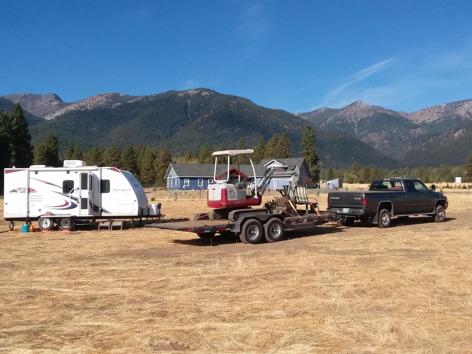
Just finished another round trip to Baker City and back hauling the mini-excavator both ways with the new 245 tires. Fuel mileage ranged from 13.8 to 14.4 mpg and the truck performs great! So far, I have not experienced any negative effects from switching to the 245 tires. Also, another noted performance improvement was during two of my trips through the Columbia River Gorge with gusty winds. When semi's passed me or I passed them, there was no longer a push to the side that I felt before with the 265 tires. I just crossed over the 300,000 mile mark on the odometer. The other photo is the 5 acre parcel of land we just purchased looking at the Elkhorn Mountains. - John
-
I am thinking the same thing. With the 245's, I towed my tractor with implements from Salem to Baker City via I-84 last week (GCVW over 16,000 lbs) and the truck had all the power I needed and delivered 13.5 mpg. Yesterday I towed the tractor back (minus a couple of implements) weighing in at 15,650 lbs via Hwy 26 and 22 at 15.2 mpg. I checked the miles per gallon from John Day (filled up with B20) to home near Salem. The power and the fuel economy are now the best they have ever been since the truck was new. Still on original injectors and I will pass the 300,000 mile mark on my return trip to Baker City tomorrow with the mini-excavator.. - John
-
I have now driven over 1,600 miles with the 245/78R16's and I am very happy with the results. About 700 miles of the driving has been towing within a 60 mile radius ranging from 15,000 to 19,600 lbs gross combined weight. With the 6 spd transmission and a 3.38:1 ratio for second gear, I can easily perform second gear starts on flat ground fully loaded now. I like that very much. Heavy loads are now much easier to get up to speed without working the engine. Sunday, my wife and took the travel trailer from home (near Salem, OR) to Baker City and deadheaded back. The trip out yielded 14.5 mpg (12,500 lbs GCW), the trip back yielded 22.3 mpg. I am very happy with that. The trip each way is about 335 miles. MPG's were hand calculated. I will be taking the tractor with implements to Baker City on Thursday and will be expecting to weigh in at about 16,000 lbs. I will post the MPG results later. Everything that Mopar1973Man posted about improved performance has happened for me by going with the smaller tires. With the new 3 1/2 turn stop to stop steering box, the new clutch, and the smaller tires, this truck drives far better now than it ever did when it was new. - John


