
IBMobile
Staff
-
Joined
-
Last visited
Everything posted by IBMobile
-
Which make and model is the kit and can you post the wire diagram? What year and model is your truck? Your signature is not filled out. Has it ever had a remote or power locks before like the high line model?
-
Look in this article in the "Repairing A/C System" section.
-
I like it. It would work for me. You could even paint the parts to match. Your thinking out side the box and coming up with a solution for a need with parts that are readily available and posting it is what this four is about.
-
Switch it around, you drive the Honda and your wife drives the truck; then you'll know what to think of it.
-
With the first (front) and third (rear) switch commanding its own motor to operate in one direction but not the other tells me those switch contacts are dirty/bad. The motors are good because they work with the second switch.
-
One way to tell if a t-stat is stuck open is to start the vehicle cold and let it run at idle. If the upper radiator hose at the radiator slowly warms up until it is hot the t-stat is stuck open.. With a normal operating t-stat the hose will stay cold then when the t-stat opens it is hot, no slow warm up.
-
That's what is great about this forum; the willingness of people always looking for a better/easier way to do something or the next best product to install on their truck and posting it. When you find it your wagon can get crowded quickly.
-
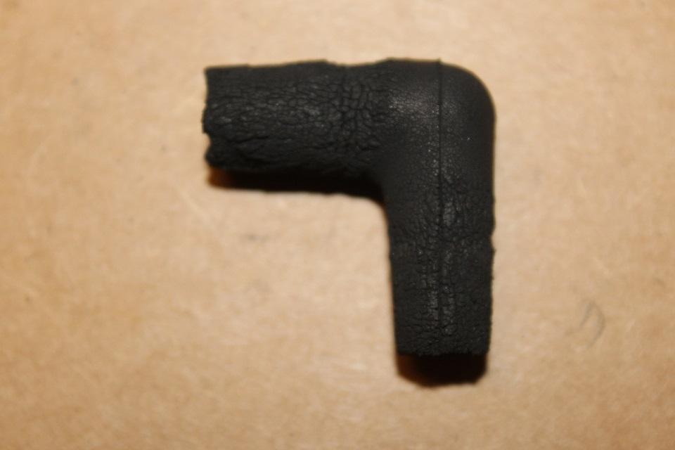
I found a piece of vacuum hose that fits just right; just cut it a little longer to make the 90° turn. You probably have a piece laying around.
-
It's the Merry Chicken Molting Season
-
That wouldn't do it. The power to the fuel pump would be battery/PDC fuse, to relay terminal 30, to relay terminal 87, to fuel pump. In a proper installation the fuse would blow. The ECM powers relay terminal 86 to the relay solenoid. The power draw on the ECM would be .175 amps at 14V. They are resistor protected.
-
I think this is the wire diagram that will work for you. To test a motor apply 12 volts to one wire going to a motor and a ground to the other wire. To test the driver power seat horizontal motor apply 12 volts to pin p17 red/light blue wire (not the red/light blue wire from the circuit breaker) and ground pin p15 yellow/light blue wire; the motor should move one way. reversing the power and ground will make the reverse. The other motors can be tested the same way by applying power and ground to them.
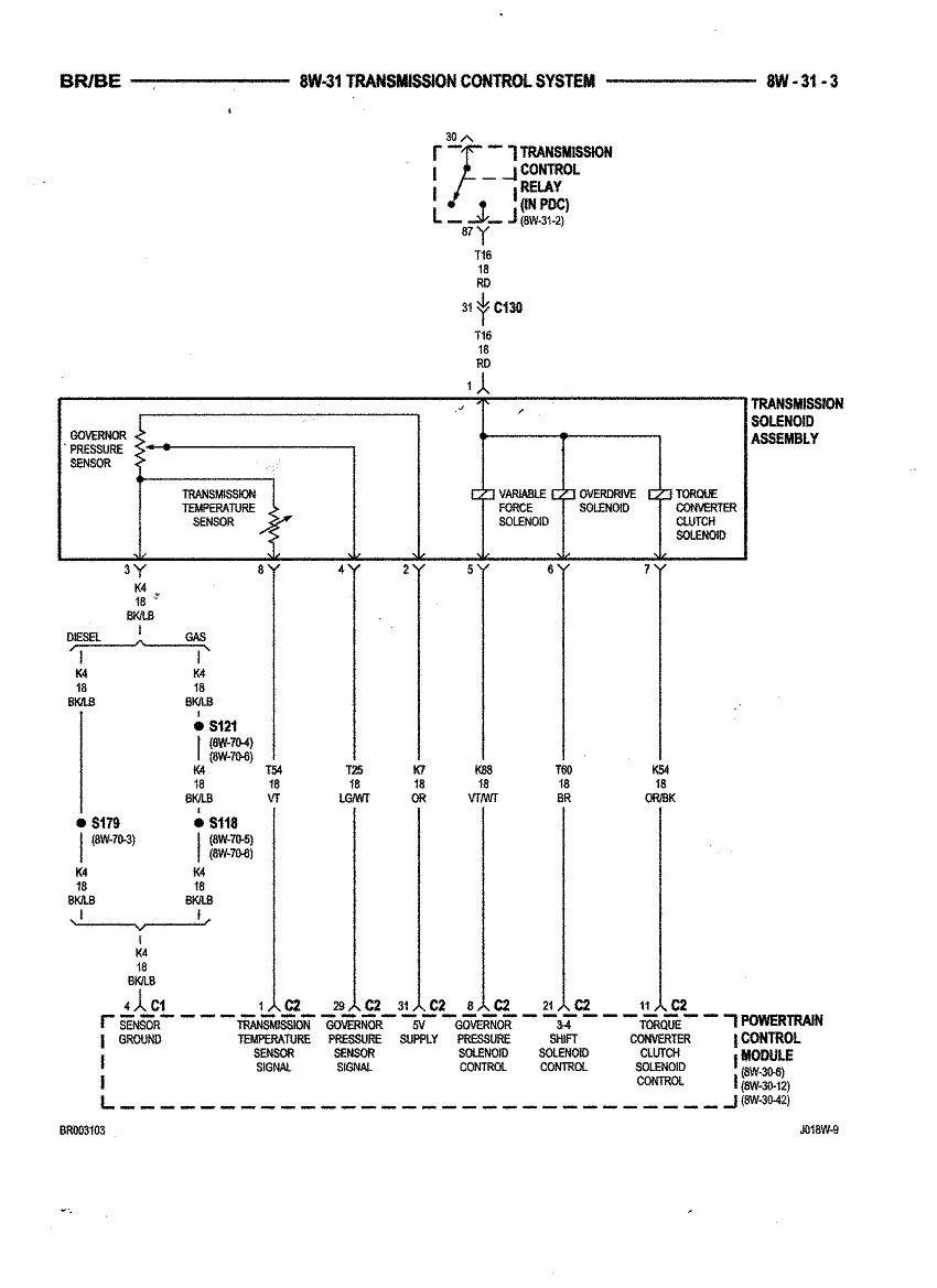
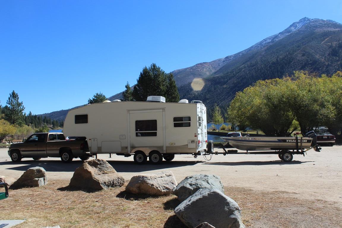
 From the FSM "STANDARD PROCEDURE—COOLANT SELECTION-ADDITIVES The presence of aluminum components in the cooling system requires strict corrosion protection. Maintain coolant at specified level with a mixture of ethylene glycol based antifreeze and water. If coolant becomes contaminated or looses color, drain and flush cooling system and fill with correctly mixed solution." So, the factory calls for ethylene glycol, the green stuff, which has anticorrosive phosphates and silicates. This type of antifreeze calls for a flush and change every 30,000-36,000 miles or 24-36 months. The FSM calls for the first coolant flush and change at 52,500miles or 42 months which is to long a time and the Ph level can fall well below 8.0. This is one of many articles I found on engine antifreeze. https://www.hemmings.com/blog/2014/08/01/tech-101-the-colors-of-antifreeze/All the diagrams show the power to the seats at the red/light blue wire. I don't see any pink wire in the seat diagrams. Are these seats out of a standard cab or a club cab?May be these diagrams will help. They are for a 99. The power seats are in them.Walmart https://www.walmart.com/ip/Super-Tech-Antifreeze-Coolant/16645420Please fill out your signature so we can better help: what year, model, transmission, any modifications. You need to do some diagnostic work. Since more problems manifested after moving the wire harness you my want to start by checking if there are any shorts or open circuits in it. How many miles on the truck? P codes 1000 or higher are manufacture vehicle specific.Just did this last week on shower/tub fixture that was dripping. I thought it was a Delta faucet but when the Home Depot associate saw the part he knew it was a Price Pfister. Took the old part out, new part in, fixed, saved a bunch of money.Data link shielding is usually a braded cable around a wire or wire bundle. It is uses to keep stray electromagnetic from interfering with a low voltage signal. it acts like a Faraday cage. Sometimes the specs call for the ends to be grounded.I have one as a spare under my back seat.Some places you can't. It's BTU rating is just below oak. The tree is an invasive species. It is a fast growing tree brought here from Australia by the rail road to make ties from it. They found that it was not good for that because as the tree grows the trunk twists. I don't know how the free range chickens will win; looking at that would kill any pecker.I finally got firewood for my wife's winter ambiance. My son and a worker went and got 4 truck loads of eucalyptus that the utility company cut so it wouldn't touch their high voltage lines. Two loads were cut last week and two loads were from 2 years ago so that will be ready to burn. Now all I have to do it get the grandkids over here to help split it. Another 2000 24 valve pulled up to get the free wood. My truck is on the left. My son Web (on the left) with Raphael unloading.I've replaced the solenoids without removing the valve body. Unplug the electrical connector at the left side of the transmission and clean the area around it Remove the oil pan and filter. Remove the governor solenoid and transducer. Remove the 3 screws holing the overdrive/TCC solenoids. Now watch this video on removing the 3-4 accumulator housing; the top of the accumulator is where the wire connector is attached. The screw that attaches it is different than the others, don't mix them up. https://www.youtube.com/watch?v=D-ctMbta0-I The O-rings on the connector should be lubed so it will slid into the case and not be damaged. Install the 3-4 accumulator per the video. Now install the new OD/TCC solenoids then the governor and transducer and plugin them into the wire harness.. install new filter then pan with gasket. The torque on the T-25 screws is 30 IN-LB and pan bolt is 10 FT-LB. If you can let the truck sit over night so fluid can drain down before taking the pan off. You'll get more fluid out that way.What number grit sandpaper and what is the solution?