


IBMobile
Staff
-
Joined
-
Last visited
Everything posted by IBMobile
-
Fine out how much they are going to charge to mount and balance. Some of the shops I use charge $10 no receipt and others $25 plus State waste fee, plus a disposal fee, and any other BS fee they can think of. When you get the tires be sure to check the production date on the side wall. You don't want a tire that's already a year old. It will look something like this (2119), 21 is the 21st week of the year 2019.
-
OK, the way your truck died is the same way mine did when the VP44 died just north of Riggins, ID almost two years ago. I suggest you do a VP44 hot wire test.
-
Is the engine still not starting or did it restart?
-
and a Colt 1911 I have the same fuse set up in my 5th wheel between the batteries and a power invertor; 15 years now and no problems. You carry spare fuses for the two fuse boxes so carry one more fuse for the alternator, not hard to do. @Threadzy I like the fuse block and where you put it
-
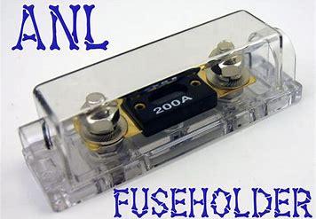
@JAG1 had told me about resettable circuit breakers tripping falsely so I put something like this in with a 150A fuse mounted to the right battery tray.
-
I get them from Parts Authority. I think they sell retail also. http://partsauthority.com/ locations https://www.bing.com/maps?q=parts+authority+auto+parts&form=EDGSPH&mkt=en-us&httpsmsn=1&plvar=0&refig=4d87e10a971047169c4c3e0993c89ffc&PC=HCTS&sp=1&qs=HS&pq=parts&sc=8-5&cvid=4d87e10a971047169c4c3e0993c89ffc&cc=US&setlang=en-US Rock Auto has them but the your paying shipping from and sending the cores back. This is for a 03. https://www.rockauto.com/en/catalog/dodge,2003,ram+2500+pickup,5.9l+l6+diesel+turbocharged,1413470,brake+&+wheel+hub,caliper,1704
-
Diesel Auto Power was the go to for me when I needed to replace my VP44 and upgrade the injectors to RV275. Good customer service and fast shipping. The prices are about the same for quality parts no matter who sells them.
-
If you go with rebuilds DO NOT use Oreille's. Did a brake job 2 weeks ago where the customer supplied the parts. I went through 3 left calipers to find a good one. I normally use the Centrex brand; never had a problem with them and yes they come with brackets.
-
That's why when I'm in the bone yard I try to snag all those little parts and put them in the shed for "just in case". Pay a couple of dollars now or "no longer available" later.
-
I have to agree with @KATOOM about this. I deal with this weekly where a lot of the parts out there are junk; then sometime I find who makes the OEM part and it's just as good as the original.
-
Let's see what Volkswagen has to say about that... "Yes, taken to the wood shed trouble. They must be from that the last group that fled from California. Here in California the police are considered a revenue generator for the city/county/state so there are a lot of them around.
-
Haven't there been other tuners that tweak the emission systems on vehicles that the government took criminal and/or civil action against?
-
It's acting like mind did when the VP44 failed, Do the "Hot Wire "test to verify pump.
-
It sounds like my truck with 112k on it or bad hearing striking here also.
-
@wil440 is right about locking out overdrive and going up hills in 3ed locked. I do it all the time; slow to 55, lock out O/D, lockup torque convertor, set cruise control, kick back and get up the hill. Going up the hill in 3ed also keeps the exhaust temps down.
-
I had to get a close up
-
We need to sell those in the web site store an have @dripley in charge. I think he personally knows the model on the pillow.
-
Just woke up at 3:45 an the mind kicked on full speed, It'll shut down when it's time to get up,
-
I made my own. I measured the openings, then went to a fabric store to get the foam. The store I went to sold 3 different densities of foam and cut it to size with a hot wire cutter. I used the medium density foam, didn't cover them and did not have to cut a hole in them for the crank handle. They're still in great shape 14 years later.
-
From the FSM, how to check turbo charger shaft for play.. (3) Visually inspect the turbocharger compressor housing for an impeller rubbing condition (Fig. 25). Replace the turbocharger if the condition exists. (4) Measure the turbocharger axial end play: (a) Install a dial indicator as shown in (Fig. 26). Zero the indicator at one end of travel. (b) Move the impeller shaft fore and aft and record the measurement. Allowable end play is 0.038 mm (0.0015 in.) MIN. and 0.089 mm (0.0035 in.) MAX. If the recorded measurement falls outside these parameters, replace the turbocharger assembly. (5) Measure the turbocharger bearing radial clearance: (a) Insert a narrow blade or wire style feeler gauge between the compressor wheel and the housing (Fig. 27). (b) Gently push the compresser wheel toward the housing and record the clearance. (c) With the feeler gauge in the same location, gently push the compressor wheel away from the housing and again record the clearance. (d) Subtract the smaller clearance from the larger clearance. This is the radial bearing clearance. (e) Allowable radial bearing clearance is 0.326 mm (0.0128 in.) MIN. and 0.496 mm (0.0195 in.) MAX. If the recorded measurement falls outside these specifications, replace the turbocharger assy.
-
If you want any more coking from her LET IT BE. She must have gone to the same cooking school as my wife. If it isn't over cooked it isn't done.
-
Grid Heater Bypass Simplified The method described below is a simplified way of turning the grid heaters on and off when starting the engine and reducing the electrical load on the alternator without setting a P0380/P0382 code. The bypass solenoid is a 300amp rated Ford type starter solenoid. When both grid heaters are on there is about 180amp draw and after start up the draw is reduced to 90 amps so the bypass relay has a 50% plus overload safety factor. Suggested Parts List 1 Standard Motor Parts starter solenoid SS-598 (bypass solenoid) 1 automotive on/off switch DC rated (your choice of style) 1 ATC fuse holder or fuse block (needed if not using fuse in PDC) 1 5amp fuse 13” 6AWG wire cable 5’ 18AWG wire red 5’ 18AWG wire blue 3’ 18AWG wire black 2 6AWG 5/16” copper wire ring terminal 3 22-18 AWG #10 ring terminal 2 #10X32X3/4” screw 2 #10X32 nut 4 #10 washer 4-5” of heat shrink (for the 8AWG cable terminals) 5’ ¼” plastic split wire loom 1 pack of 5-7” plastic ties 1 roll rosin core solder Putting It Together Disconnect both batteries; remove left (driver’s side) battery and battery tray. On the side of the battery tray fit the bypass solenoid and mark holes to be drilled; you may have to grind one side of the bypass solenoid mounting bracket to have it fit flush on the side of the battery tray. Drill 2 holes, 13/64”-7/32”, where marked on battery tray and mount the bypass solenoid with the #10 screws and nuts as shown below. Note: the bypass solenoid is grounded through its body so a black ground wire, with a #10 ring terminal at each end, is attached to one of the mounting screws and the other end grounded to the body. Reinstall the battery tray. Left battery tray with solenoid attached. Find a place in the cab where the switch type you chose will fit and be readily accessible. We used a rocker switch mounted in the kick panel below the steering column. For power you can tap into the fuse box on the left side of the dash. Find a terminal that has power only when the ignition key is in the on position. This is where you can add an ATC fuse holder with a 5amp fuse. Connect one end of the red wire to the fuse holder and the other end to the switch. Connect the blue wire to the other switch terminal and run it through the rubber grommet in the fire wall and with a #10 ring terminal connect it to the bypass solenoid terminal marked S; cover with ¼ “ split wire loom. Make up the 6AWG cable (an 8AWG cable will work also) with the 5/16” copper ring terminals and heat shrink. I solder my cable ends on using a small butane torch but you can use a large cable end crimper. Be sure to index the orientation of the cable ends to the cable before attaching them so the ring terminals fit squarely on to the battery and solenoid. The cables for the grid heat solenoid and battery power can now be attached to the bypass solenoid; the battery power cable to the firewall side of the bypass relay and the cables for the heater solenoid to the other side; reinstall the battery, connect all the terminals and reset the apps. Left battery tray installed with bypass solenoid. Notice position of the cables. Note: I have experienced a P1291” No temperature rise seen from intake heaters” when the temperature is below 35°F and the heaters are turned off right after starting the engine. I suggest leaving them on when first starting in cold weather for a minute or two. Note: It was first suggested to use an SS-581 starter solenoid, this solenoid does not have a protective diode in it and may cause a voltage spike that could damage sensitive electronic components. A SS-598 solenoid should be used in its place. This was installed with the help of JAG1 on his 2001 Ram 2500 diesel utility box work truck. Written by: J. Daniel Martin AKA IBMobile 7/6/2019
- 3 comments
- 1 review
-
-

- 2
-
-
Grid Heater Bypass Simplified The method described below is a simplified way of turning the grid heaters on and off when starting the engine and reducing the electrical load on the alternator without setting a P0380/P0382 code. The bypass solenoid is a 300amp rated Ford type starter solenoid. When both grid heaters are on there is about 180amp draw and after start up the draw is reduced to 90 amps so the bypass relay has a 50% plus overload safety factor. Suggested Parts List 1 Standard Motor Parts starter solenoid SS-598 (bypass solenoid) 1 automotive on/off switch DC rated (your choice of style) 1 ATC fuse holder or fuse block (needed if not using fuse in PDC) 1 5amp fuse 13” 6AWG wire cable 5’ 18AWG wire red 5’ 18AWG wire blue 3’ 18AWG wire black 2 6AWG 5/16” copper wire ring terminal 3 22-18 AWG #10 ring terminal 2 #10X32X3/4” screw 2 #10X32 nut 4 #10 washer 4-5” of heat shrink (for the 8AWG cable terminals) 5’ ¼” plastic split wire loom 1 pack of 5-7” plastic ties 1 roll rosin core solder Putting It Together Disconnect both batteries; remove left (driver’s side) battery and battery tray. On the side of the battery tray fit the bypass solenoid and mark holes to be drilled; you may have to grind one side of the bypass solenoid mounting bracket to have it fit flush on the side of the battery tray. Drill 2 holes, 13/64”-7/32”, where marked on battery tray and mount the bypass solenoid with the #10 screws and nuts as shown below. Note: the bypass solenoid is grounded through its body so a black ground wire, with a #10 ring terminal at each end, is attached to one of the mounting screws and the other end grounded to the body. Reinstall the battery tray. Left battery tray with solenoid attached. Find a place in the cab where the switch type you chose will fit and be readily accessible. We used a rocker switch mounted in the kick panel below the steering column. For power you can tap into the fuse box on the left side of the dash. Find a terminal that has power only when the ignition key is in the on position. This is where you can add an ATC fuse holder with a 5amp fuse. Connect one end of the red wire to the fuse holder and the other end to the switch. Connect the blue wire to the other switch terminal and run it through the rubber grommet in the fire wall and with a #10 ring terminal connect it to the bypass solenoid terminal marked S; cover with ¼ “ split wire loom. Make up the 6AWG cable (an 8AWG cable will work also) with the 5/16” copper ring terminals and heat shrink. I solder my cable ends on using a small butane torch but you can use a large cable end crimper. Be sure to index the orientation of the cable ends to the cable before attaching them so the ring terminals fit squarely on to the battery and solenoid. The cables for the grid heat solenoid and battery power can now be attached to the bypass solenoid; the battery power cable to the firewall side of the bypass relay and the cables for the heater solenoid to the other side; reinstall the battery, connect all the terminals and reset the apps. Left battery tray installed with bypass solenoid. Notice position of the cables. Note: I have experienced a P1291” No temperature rise seen from intake heaters” when the temperature is below 35°F and the heaters are turned off right after starting the engine. I suggest leaving them on when first starting in cold weather for a minute or two. Note: It was first suggested to use an SS-581 starter solenoid, this solenoid does not have a protective diode in it and may cause a voltage spike that could damage sensitive electronic components. A SS-598 solenoid should be used in its place. This was installed with the help of JAG1 on his 2001 Ram 2500 diesel utility box work truck. Written by: J. Daniel Martin AKA IBMobile 7/6/2019 View full Cummins article
-
I finished the article "Grid Heater Bypass Simplified" last night and will post it later today after my wife proofs it.
-
Rear main seal housing, then oil pan, then the seal. The pan gasket will come up to meet the seal housing. Also, if any of the seal housing gasket is hanging below the housing after the housing is mounted to the block you can trim it before putting on the oil pan.. The other way is you have the seal housing sliding over the pan gasket.


