


Haggar
Unpaid Member
-
Joined
-
Last visited
Everything posted by Haggar
-
D, Good. From your testing you do know that the compressor will work, if it gets the proper signal from the PCM. This could be PCM, or most likely either the command to the PCM from the a/c switch is missing, or the "allow" command from the high and low pressure switches is missing. Can you disconnect your PCM wires and feel confident testing circuits there?(i hope you can, this will get you the most information quickly) I would very first thing (look at FSM pages 8w 80-69 attached): With the A/C mode switch in one of the AC positions, disconnect the C3 connector. Perform 2 tests. 1. Check continuity to ground for pin 22 (on the wiring connector, not the PCM). This will ensure the ground is connected, and that both high and low pressure switches are in the proper position for the AC to function. (you can do this test with truck not running. The position of the ignition switch does not change the wiring.) 2. Check continuity to ground for pin 23. This should have continuity to ground in the proper modes. The continuity should disappear if the mode is changed to a non AC mode. (This should also work without starting the truck. you are testing the wires to the PCM and the position of the ignition switch should not make a difference) I know what you are saying about the PCM. It is possible to have killed it. But, of all the components in the PCM you could have killed, this is the least likely. I find it VERY hard to believe that a short would have killed only that path, without disturbing other similar paths. I hate for you to waste your time and money on a very unlikely path without testing the areas where the most problems occur. Hope that helps! Hag 2001 FSM Ram 8W-80-69.pdf
-
D, No worries. The above will tell you if you are getting a command out from the PCM. If you do see it switching, you will know your problem is just in the compressor clutch relay, or compressor clutch circuit, or the clutch itself. We kindof started this trouble shooting backwards..... For our AC to work many things must happen. 1. A request to the PCM for air conditioning must be made. This is an electrical part of the knob on the dash. You only get AC request in certain positions. (see pages 8w 42-3 and 8w 42-4) 2. The PCM must see the proper signals from both the high and low pressure switches in the lines. (see the FSM pages 24-20 to 24-22 I attached) 3. An output signal will be generated (the one you are testing in the post from above) to change the states of the relay. Pins 22 and 23 on the PCM are the above inputs. (see FSM page 8w-42-3 and 8w-42-4) Pin 23 (AC select input) will see a ground signal from G201 Through the fan switch on the light green/white wire. (please excuse my ignorance in this area. I have not had the actual heater controls out and actually tested them... I am totally making a mental model from the wiring diagram...) You can check this actual request by using the ground ohms test like the previous post. (with AC in OFF, there should be no continuity. As you move through max ac etc, you should see the meter become continuous with ground, until you hit certain modes that don't call A/C then you will get A/C signal again with defrost modes. Pin 22 (A/C switch sense) Again from the G201 connector you should see ground anywhere along this path. Both the high pressure and low pressure switches are in series. The high pressure switch is normally closed. (it opens at approximately 450psi) The low pressure switch is NORMALLY OPEN. It only closes if there is enough refrigerant in the system to have more than 37-43 psi on the switch. I hope this helps. It is very odd for AC troubles to be a PCM issue. Of all the A/C problems I have seen, it was never the PCM, but always somehow the sensors or wiring or command to the PCM to be the issue. Hag 2001 FSM Ram 8W-42-3.pdf 2001 FSM Ram 8W-42-4.pdf 2001 FSM Ram 24-20 to 24-22.pdf
-
D, Ok, I am going to assume you have a Volt ohm meter (VOM). (digital or analog is fine) Set the meter to measure ohms. Connect one lead to the NEGATIVE side of the battery. (you could connect it anywhere on the chassis just make sure it is connected to ground, and VERY GOOD.) Remove fuse J and fuse 11. (I put this step in before I realized the FSM tells you exactly which contacts are which) This will keep you from accidentally blowing those or your meter. (fuse 11 also has the central timer relay on it, so automatic locks and such may not function properly while it is out) With one end of the VOM still connected to ground, use the other to probe the slot that corresponds with terminal 85 on the clutch relay socket . (if you are unfamiliar with the din terminal designations, there should be a wiring diagram of the relay on its side. also sometimes if you look closely near the pins on the relay, the terminal number may be molded or printed there.) I have attached the page from the FSM which shows the actual pin designations to locations in the PDC. When the ac is commanded ON. your VOM should show a very low resistance to ground. (0.1 ohm type number) It should be similar to the same number you get when touching your two probes together. When the AC is commanded OFF. you should read infinite resistance, or the same number you seen when holding the two probes very far apart. (mine actually reads OPEN LINE, not a number) This is how it should react when operating properly. You will at least know that the PCM is not your problem. (well trouble shooting is more complicated.... but I can step you through this if need be.) HTH Hag 2001 FSM Ram 8W-10-2.pdf
-
D, no, the PCM when controlling the AC clutch relay, only connects the negative side of the relay coil to ground. It will NOT give you a 12v + signal. It will only become continuous with ground. See the wiring diagram I attached. Let me know if you need to know how to test that. GL Hag 2001 FSM Ram 8W-42-5.pdf
-
I have attached the FSM page for a 2001. On what is on that fuse. It powers the ECM, PCM, and "fuel pump relay" (the main hot for the VP) I think you have a short in one of the wires. (between the fuse and one of those three components. The harness is damaged from rubbing on something.) You are going to have to look very hard and find it. My first suspect would be the large loom coming out of the PDC all wrapped in tape, it goes down the drivers inner wheel well sort of towards the ECM. This place just seems to have a lot of issues from things rubbing it. Jbayes brings up a good point too.... How are you powering your lift pump..... could your lift pump be damaged or otherwise pulling too much power? I will have to research it, but this fuse may provide the actual lift pump power that enables the stock lift pump through the ECM internal relay... Good luck! Hag 2001 FSM Ram 8W-10-12.pdf
-
Here is the 2wd section from the FSM for a 2001. Be careful of the coil spring. It can kill you. HTH Hag 2wd ball joint replacement from 2001 Factory Service Manual DodgeRam.pdf
-
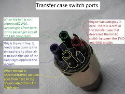
Nomore, IIRC, there is a detent ball at the bottom of the new switch you got. That detent ball rides on a shaft in the TC. The shaft has flats and round to actuate it when it is in the proper position. (I cant remember if it is the mode shaft or the range, but think it is the mode.) Take the vacuum switch back out and manually operate it with your hand. (push the little ball in) and see if it directs the vacuum properly. I found another drawing that might help you with which vacuum line goes where (note, I have not verified this, but seems like how I remember it.) Looking at the switch from the "top" (vacuum side) down. The vent goes between the arrows. I just found another picture from a jeep forum (http://www.wranglerforum.com/f218/vacuum-issue-in-4wd-system-with-light-1677905.html) notice for his he has reversed the vacuum and vent ports. but that does not matter as long as you swap the "outputs" . Hope this helps
-
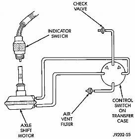
nomore, here is a picture i posted in another thread. Yes the there is a three way switch on the transfer case. It senses the location of your transfer case lever. It provides vacuum to the red or the black based on if you have selected a 4wd mode or not. If it is original, red is 2wd and black is 4wd. (red pulls the CAD vacuum motor to disconnect the coupling. Black pulls the vacuum motor to engage the axle coupling. Here is a video of a guy checking his out. I did not watch it all but it seems ok. he never shows the actual switch. that goes bad rarely. you can easily disconnect the vacuum plug from the switch from below and test each of the vacuum tubes. Our switch, unlike the GM verson has 4 tubes connected. (GM only uses 3) our 4 are White=vacuum source, Green= Vent to atmosphere (to change directions of the vacuum motor, you must exhaust (let the side under vacuum return to atmospheric pressure) , Red = 2wd by disconnecting the axle coupling if the vacuum motor is actuated in that direction, Black = 4wd by moving the vacuum motor and coupling to engaged the shafts.
-
Gould Gear and electronics. http://www.fixinrams.com/ Best place I have found for vacuum pump information. Great to talk to people also. Hag
-
Silver moose is dead on. Use a hand held vacuum tool like this https://www.harborfreight.com/Brake-Bleeder-and-Vacuum-Pump-Kit-69328.html connect it where the lines connect to your vacuum pump now. pump the handle, and if it never pulls a vacuum, there is a line loose somewhere. Keep pumping and have someone listen around for where the air is leaking from. (they should easily hear the hissing, unless it is a huge hole) after you have fixed your leak you should be able to keep pumping the handle and have your HVAC vents move (no, truck need not be on) and your 4wd actuator should try to move. (no the light won't come on with the key off, but the valve is mechanical and connected to the Transfer case near the shifter) To check your vacuum pump on the motor, connect this tool directly to the vacuum pump. start the truck and read the gauge. (the vacuum pump on the truck, if working and no leak (there should be no leak you are connected directly to it) you will see how much vacuum your pump on the truck is pulling. Hope this helps! Hag
-
Go easy on the quick cycling of the key for the "prime" hits of the lift pump and WTS lights. I do not know the programming, or how it is programmed, but if you quickly bump then shut off and re-bump, the WTS light and lift pump timers get out of whack.(good IT approved technical term. Hold over from the mechanical timer days!!!) Give the system a good amount of time to reset the timers or you will chase your tail. HTH Hag
-
T and Ibm, Agreed, I never said it was much, but it will change. I think on my truck I get a full degree or 1.25 degrees change in that range of movement on camber (total indicated, so each wheel is half that.)(thinking about it more it could be half that.... my memory is terrible) . Caster changes much more. You cannot change the caster on our trucks without changing the camber. They are both tied together. (unless you install offset ball joints.) But when you do change the castor, the camber will change. There is nothing you can do about it. Hag
-
Dripley, Your are right it "does not change camber" the camber is set by the ball joints in the axle. So the camber relative to the axle is unchangeable. (without offset ball joints) BUT It will change the camber (relative to the ground, not the axle itself) because you rolled the axle, with the pivot point being the upper (control arms) link connections. You can picture this in your mind better if you thought of a straight axle with camber in the wheels, and then turned the axle upside down. by rolling the axle about itself by 180 degrees you would take your camber (lets say it was negative 2 degrees) and make it opposite (the camber would now be positive 2 degrees. (lets ignore we just made caster go way out of wack by rolling the axle that far) hope that helps you visualize it. Hag
-
Not, What makes you think they are out of whack? Those adjustments rotate the axle relative to the upper links. This will affect caster and camber the most. (since our ball joints are fixed, rotating the axle is what gives us any chance of either of those, short of offset ball joints) If the alignment shop set them and they are still tight, That is what worked out the best on their machine that day for how the truck was loaded. Leave them alone then. (using a machine, they could be slightly off from each other, due to all the manufacturing tolerances it is adjusting for.) I think I have mine set so the lower arm is the longest, my truck seems to drive best there. Just look close at all the stuff and make sure it is not worn out or loose! ( I noticed one of my cam bolts came loose one day... that is why they are both the same on my truck.) Hope that helps, Hag
-
Wow, Sorry CT!!! I didn't notice the date! Didn't mean to drag something out of the Crypt. It showed up as unread. I guess it had been awhile since I browsed this part of the forum. Hope the new ones work great for you!! Hag
-
CT, What I have found is the Passenger rated tires, while riding well, don't give me the confidence when pulling or loaded heavy. (sidewalls seem soft.) We have put a set on Helga's suburbasaurus, and for family trips and other stuff it is fine, but I won't pull a trailer over 1k lbs with it. Snow and rain have been fine though. So we are happy with them, but I definitely wouldn't put them on the rattle monster. Just my $0.02 hope it helps Hag
-
The zones are the parts stores like autozone, advanced auto, some of the newer Napa's, some O'reillys.... They are like walmart (and Lowes), they might have it, but nobody really knows, don't know where it is and/or what it is used for. but hey they have soft drinks and air fresheners. (these are the places that need to know if it is an automatic and if it has AC and power steering to tell you what oil you need.) For tubing connectors, you are looking for a Dorman 47430 . This is an assortment of different sizes (for straight connections). But if they can guide you to that area, you may find other things etc that might work better. They will be in "blister packs" either in the Red HELP packaging or very close to that. Hope that helps! Hag
-
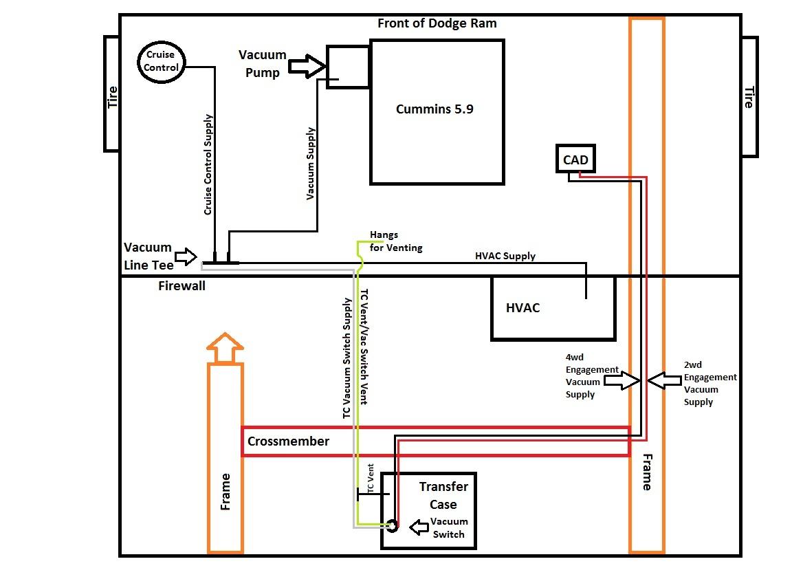
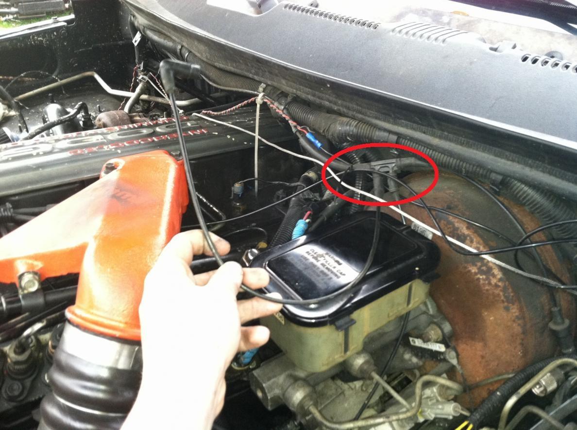
The diagrams in the fsm and the descriptions in the parts manual are not helpful... 5/32" tubing and vacuum hose that fits 5/32 tubing is your friend. You have a funny connector or the vacuum pump. (it is where the red cap in the picture of the pump and the power steering. it connects to the hard tubing) I have also attached a schematic of the vacuum hoses. it is for a 4wd. just ignore the lines going to the cad and transfer case on a 2wd. To find the position of the tee... it is circled in red (sorry not my truck, just plucked from webz) Mine is close to there and looks similar. That looks like they have done some replacing already. You should be able to get everything you need at one of the zones..... but a real parts store might be a bit more of a help. HTH Hag

-
I use a mini-fuse add a circuit and plug it into fuse 5 in the "junction block" which is the fuse panel on the drivers side inside of cab on the instrument panel. This is the dimmed voltage circuit, so they brighten and darken with the command from the headlight switch rheostat. Hope that helps! Hag
-
No don't loctite the nuts. Notice in the picture of the back of the motor.... your lines do not line up properly. I have been wondering why cummins used this type of "tee" to join the lines. (english fords and massey ferguson tractors are covered with them....) It is to survive the vibration and to allow a "little bit" of room for mis alignment of the tubes coming to the fitting. (but i think you have too much mis alignment) It is hard to visualize how this fitting goes together, but, make sure you slip the "o-ring" over the line, under the nut. when you insert the line into the tee, theoretically there should be metal to metal contact of the tube to the tee fitting. The nut crams the "o-ring" around the tube and inside the tee fitting. This has to happen in three places simultaneously.... The only way i found to do it with the motor in the truck, loosely put the line on the back of the the head, with the tee already started. Take the bracket loose from the block and start the return tube. Then see where those line up to the VP return.... and hope it is ok.... now try to see where the bracket on the return is compated to its proper location..... You can't use this tab to pull all of it back into place, you have to bend tubes so it is stress free. I hope this helps you! Good luck! If I have to do this again, I will be using parker push lock banjos etc to do it. That is a total pain. Hag
-
Jag, Let me know how your tests turn out. I started thinking about some of these problems with my current setup... When I drain the system, the FRRP that I use will NOT self prime..... Unless, I disconnect the outlet of the pump at the inlet to the filter manager..... The pump will then self prime, and if I re-connect it while it is flowing, never have another problem with it. Apparently, with the head of the filter manager, IP and return lines, it doesn't have enough NPSH to self prime, but once primed is fine. ( the FRRP is in the stock location, so Centerline of pump is at or above fuel level.)
-
Jag, Have been having trouble sleeping thinking about your issue. Air dog doesn't have head/flow curves for their pumps. I have been thinking about developing some. (I would really like to know the NPSH requirements!!!!) I think part of your problem is the 150gph pump being fed by "60 gph" and "90 gph" filters on the suction side. It appears from the parker catalog (depending on the racor part number) most of these 90gph use 1 psi drop across the filter to establish their flow rate. Since you are moving more fuel through than their design, the differential pressure needed to pass that fuel through goes up. Just how much it went up I can't find. (looking for flow/head diagrams as I type this) (ok found this one .pdf is attached) Notice the flow head for the 490R series. That is 1 psi differential to get 90gph... But look at the shape of the curve, it is going over 2 psi to try to perform at 150gph (assuming it follows that curve and does not go more exponential).... (notice the shape of the curve for the 120 is completely different, the design is different apparently.) The whole thing is you are in a suction throttling situation. You just happen to be right on the hairy edge of the NPSH required for the pump to operate. I think you are cavitating and making vapor. This is why the regulator in the pump starts wandering... (it is designed to regulate liquid, not vapor) I don't think changing output pressure will help much either. since the pump internally recirculates, the temperature is already increasing, which makes cavitation occur more easily. (this is why some of the regulators return to tank.... to try and cool this fuel. (Though a closed system will eventually heat the complete tank too....) I hope this helps. If you really want to know what is going on, you will need to add a couple absolute pressure gauges across the inlet. You may be able to pressurize the fuel tank and see if the problem goes away. If it does you know for a fact it was suction throttling. (assuming the filter can even flow that rate irrelevant of the differential pressure.) Hag Racor 490R flow head.pdf
-
No, I just cleaned it up and used 2 hose clamps and oriented them 180 degrees..... Worm clamps are the devils invention. I will go back with good spring clamps or T-bolt type clamps. Standard worm clamps put too much of the clamping force on one side, the force does not uniformly distribute itself well. Not exactly sure if it is a change in the "rubber" of the new hoses or what. I have a friend with a chevy gasser truck and we have had to tighten his clamps every spring for the last couple years... Very odd. Good luck I hope it is that simple! Hag
-
The inlet strainer on the pump is a bigger restriction to flow than the difference between 3/8" and 1/2" lines.... (my charts show a standard loss across a strainer of about 1.0 psi at 2 gpm on water...) I ran a quick calculation: the pressure drop of a foot of 3/8 steel tubing at 90gph is 0.1 psi. (for everything the same but 1/2" line, it is 0.06psi drop) Since it is on the suction side, and you have not reached the limits of the NPSH for the pump, and we are withdrawing from a vented tank, it won't affect the output pressure at all. I reran using a rougher pipe inner surface and increased the flow to 140gph. it went to 0.2 psi pressure drop. I think its ok to use 3/8" suction side.... HTH Hag
-
Change the fluid in the rear differential. No one else did it, they were too busy poking exhausts in the hood and bed and such. (being funny truck looks good and looks fun!) While you are letting the fluid drain, use a chalk marker and count the teeth on the pinion gear and on the ring gear. Divide the teeth in the ring gear buy the number of teeth in the pinion. There is your exact final drive ratio. (I think that it should be 41 on ring gear and 10 on pinion For the "4.10" on the dana 80.) You can also see if there is a positive traction in the rear too and check the condition of everything. Good luck hope that helps. Hag
