


Mopar1973Man
Owner
-
Joined
-
Last visited
Everything posted by Mopar1973Man
-
You'd like my 7" Azpen A729 tablet. https://www.azpenpc.com/shop/product/93-azpen-a729-7-dual-core-android-tablet-with-dual-cameras-hd-lcd-1gb-ram-8gb-storage-game-store-and-office-suite/
-
Just above the your throttle foot in the dash. So if your smart pull the entire dash and take it. It will take some effort to get the wiring out if needed.
-
If you going that far you could do a keyless entry, remote start and car alarm...
-
Highly suggest you use a relay for the lift pump circuit. Stock Dodge lift pumps are direct wired which is very risky.
-
You'll most likely want to get the central timer and the cab wiring (maybe). I'm assuming the wiring is all present in your truck already. Pay close attention to plugs.
-
No. No mobile apps required. This skin is mobile ready and automatically reacts to the viewport size of the mobile device. So like on my tablet it automatically changes from mobile to desktop by rotation.
-
http://www.rammount.com/device/phone_mounts This might help...
-
If you already done this testing then you might consider replacing the APPS with a timbo's APPS.
-
Go over here... https://mopar1973man.com/external-media/pdf/2000Ramparts.pdf#view=FitB&page=88 Scroll down till you get to page 106.
-
Interesting...
-
Crossover tube is because of water getting back behind the injection line nut. The line nut is not water tight so if you wash your engine off at all then the water could get into little space and rust the tip of the tube.
-
Even the chrome plated sockets will rust if given the environment to create rust. Like my set I keep in the truck they seen several rain and snow storms. Even had times where I closed the case and held it up to drain the water out. So even chrome plated sockets will rust. Now my stuff in the shop tool box I've not had any problems with them. I just wipe everything off and put it away. I'm not the typically solvent wash my tools a bit of oil film isn't going to hurt anything.
-
Be careful with grease near any kind of brake fluid system. Grease and oil will destroy seals in the hydraulic systems.
-
Maybe you got more room that I do... I've got big hands so a little bit of room goes away fast... Why not do us a favor and create an article of what you do on that pivot if you go that far...
-
Then your in for a big job of getting the pivot pin out so you can replace them.
-
For the pedal pivot I would lay a big shop rag on the floor and hose the pivot with silicone spray and see what it does for the pivot.
-
Like myself I'm running NAPA hydro's and Southbend Con OFE clutch no issues. So I really doubt it all going to be hydro's. Typically a bad hydro will bleed off and start engaging when you hold the clutch for long periods. Typically you'll see fluid wetness on the firewall side or maybe weeping into the bellhousing. I heard of on case where a pin hole was in the tubing.
-
Wiper motor park switch internally is wearing out. Mine is doing a little bit too. The only thing that could be done is replace the wiper motor.
-
Unknown on that part... The only thing I can say is hit a wrecking yard for that piece.
-
Most of it should be already there. Just need the headlight switch, fog lamp relay and the plug is typically under the radiator or near that area.
-
Most likely your not going to like it. If you wire to the headlight switch then you going to be bound by the lo beam only mode that Dodge provides. So if you turn on hi beams the fog light go off. Me personally I did something way different I use the fog light signal to toggle a relay and allow to have 2 bulbs on lo beam and then 2 bulbs on high beam. This way I kept the control from the dimmer switch and headlight switch still controls the light on or off.
-
My tools are typically used to often to really get rust on them. I don't clean them spotless either leaving a bit of oily film on most of them. Like myself for the odd stuff spray either silicone spray or WD40 on a rag and wipe the tool off. Put it away...
-
I did that way for many years...
-
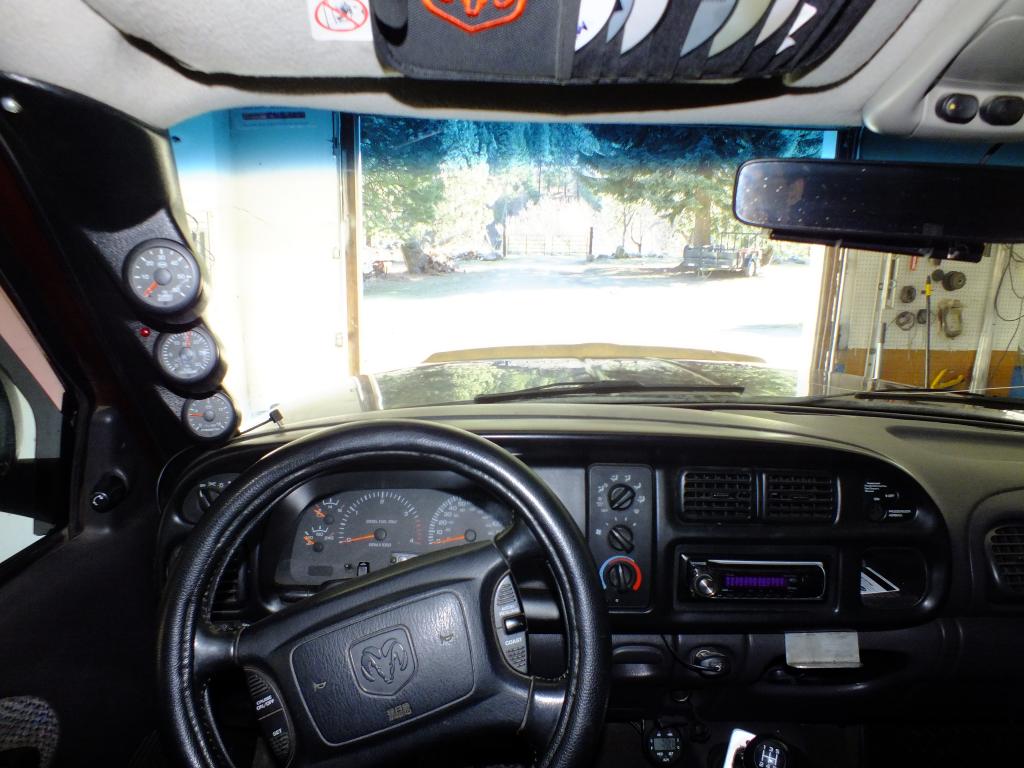
Retake... I measured the location of my eyes and shot the photo from that position. Now you'll still notice at least for my pod there is just a slight bump that protrudes past the stock line. I don't know if my old pod is different that the new ones... @TFaoro As for the Scan Gauge II clip maybe that would be a good spot for your phone gauges...
-
Still even on mechanical gauges I would still have some means of shutting down the fuel at the tap point this way if there is a failure of any type then you still capable of driving the truck.

