


Mopar1973Man
Owner
-
Joined
-
Last visited
Everything posted by Mopar1973Man
-
That's the best thing MoparMom is sitting to my right. So I don't have to get on a plane to fix the A/C just got out to the shop. I give discounts for quality beer and booze.
-
Saginaw boxes are really easy to rebuild and reseal yourself. While your redoing the box you can readjust everything to make it tight again.
-
Pretty straight forward to rebuild an alternator. As long as the case is good and the bearing spots in the case are good I would go for it. My last alternator I want to do that but the rear half of the case was fried and wasn't holding the bearing properly. I was stuck buying another reman'ed. I like the price on the diodes and parts... I wonder if Nation's Alternators would sell you one of their high amperage diodes? That would surely give you some buffer room. Not to mention I think they are mounted on copper plate to dump heat better.
-
I'm wondering about draw too. I wonder if the heater itself is drawing more current because of a issue. Unusual to hear a engine load up against a grid heater then huff as it unloads. The only time I've seen that was on the end of my last batteries at 10 years old they were getting a bit weak so it would do that load up and surge some as it unloaded. So I'm agreement with AH64ID just wondering if there is extra load that might belong...
-
That would be a nice addition to the RV /Trailer article base.
-
Another suggestion is to look at the frame design closely. That was one of the selling factors on my Jayco with the double square tube frame. Very strong compared to most ultra lites that tend to flex. @Killer223 mention the 7 gallon propane bottles. They are typically listed as 30# propane bottles. Very nice to have the larger bottles. I'm also more so a boondocker than a campground or RV park person. I love the idea of finding a turnout, wide spot, flat piece of ground and set up. Like Killer223 I'm also powered up with solar too so no generator needed, no fuel to drag around, no noise either. @Killer223 mentions the queen bed. I'm lucky there to I've got a true queen in my Jayco. Very comfortable. I was picky about the bed. There is no way I would buy an RV with a bed that I can't sleep in. So that left me look for a "True Queen" and not a "RV Queen". Slides are heavy. Not doubt about that. I've got a fairly large slide but being the Cummis is pulling it no problem. I cross the scale typically between 7,800 to 8,000 pounds depending on how much cargo is in the RV. This weight is with full tank of water and empty holding tanks. I also bought used too. Mine was a purchased back in Nov. 2010 but the RV was a 2000 Jayco Eagle 296 FBS. The only repairs I've done is a set of brakes on the forward axle, bearing packing, fixed a few minor things, and recoated the roof. @Hawkez mentions the outside shower. Mine is really handy for waste dumps. I keep a bar of soap out there and the shower is right near the dump outlet so I can wash up or even rinse my hose if there is no water available at the dump site. That has happened a few times.
-
Interesting face design. It almost looks photoshop because there is no visible rim to the face.
-
There is a o-ring. Should be able to re-use it. I'm a bit worried abut that nasty rusted nut.
-
Ask more questions... We'll teach you.
-
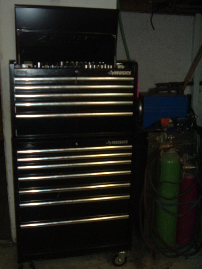
Won't work. I don't think they will let me wheel my tool box on board.
-
Typo most likely... 1,2,4 is front group and 3,5,6 is the rear group.
-
Ah... that's right.
-
But you going to throw way the CF's often talked about 2WD LO abilities. Everyone what to be able to keep their 2WD LO on the transfer case. Personally, I tend to agree with you the whole CAD axle design is PITA and typically adds more problems to simple system.
-
Hour and half is my fastest...
-
Disconnecting for a test start on a cold morning might give you a clue if the grid heaters are pulling that hard... For diagnostic reasons might be what you need to see if that is your problem.
-
Seem like the two of you need to create a nice write up of how that's done...
-
Here I got an industrial service pack just for you.
-
Ok. You are going to need a test light and a DVM. While the truck is idling just started cold check the grid heater terminals for power see if both are hitting or one is hitting. Then with the DVM hook it up to the battery and watch the battery voltage. Tell me what the DVM voltage is doing during the on cycle of the grid heaters. I'm wondering if there is a damage grid heater? Just double checking, I would have both batteries load tested and have the alternator load tested as well. That "HRUMMFF" as you call it is typically a sign of heavy draw on the alternator.
-
Just appears it was shoved in too deep that's all. As long as the clamp is positioned correctly I don't see a problem.
-
Just for learning value. Most times people with excessive blow by are informed to check vacuum lines first thing. Because a disconnected vacuum line can imitate bad rings... Being the vacuum pump exhausts into the crankcase and then vents out the crankcase vent.
-
You need to redo that lower clamp. Either the steel tube is shoved too deep or you got the clamp too high. I normally don't use any lubes on the boots this way they stick to the ends and don't blow off. I typically use a orange degreaser from Home Depot that makes the boot very slick for short time once it dres it sticks in place and a PITA to remove. No. Because the carb spray will be just sucked into the crankcase to dilute the oil... Bad idea.
-
I love your No No NO GIF...
-
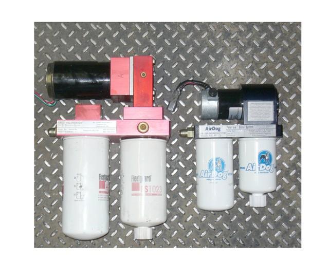
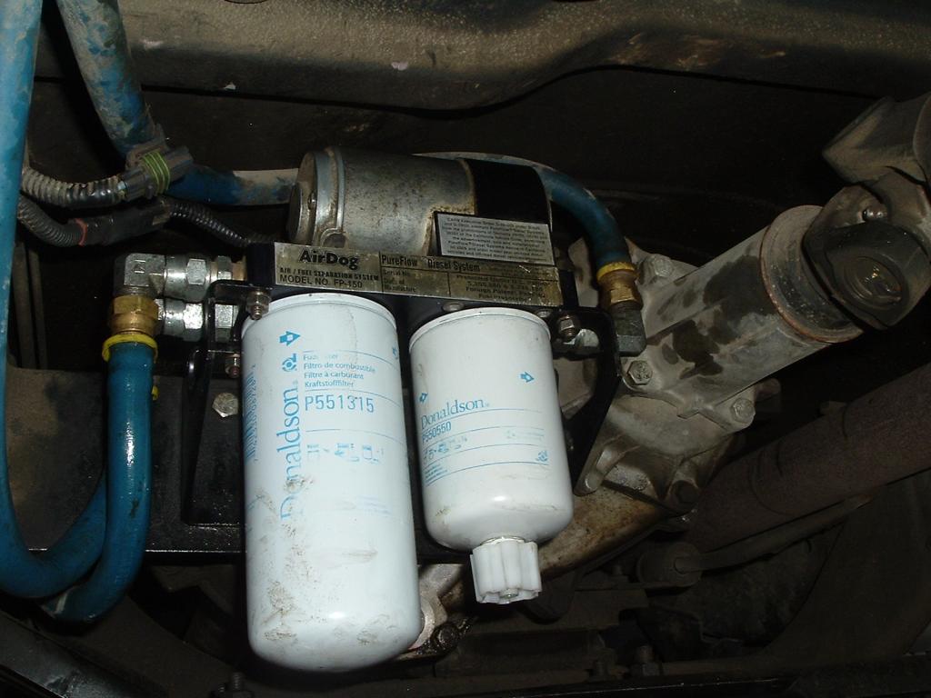
Only problem with FAS it so friggin' huge... Makes for difficult time hiding the pump and filter somewhere out of the debris path of the tires also out of the direct wind of winter cold. So the FASS can't go in my hiding spot. It just too big. So consider you mounting location very careful. Frame rail mounting will place the filters in striking path of any kicked up road debris. It would really suck to run over something and wipe out the filters.
-
$200 is steep. Master - http://www.napaonline.com/napa/en/p/NCF72354_0316483226 Slave - http://www.napaonline.com/napa/en/p/NCF73322_0316483225 Complete unit - http://www.napaonline.com/napa/en/p/NCF74013_0316483228 $129.48 is quite a savings... The only difference you have to bleed the system yourself. You still have to install as a mass unit with either the $200 unit or pull it, rebuild, bleed, and install for less.
-
Keep your eyes over in CF for guys putting in stereo systems typically that is the first thing to get chucked in the trash.

