


Mopar1973Man
Owner
-
Joined
-
Last visited
Everything posted by Mopar1973Man
-
You could change out the entire rail cheaper... As for the sample of fuel it looks like you got a load of summer fuel and the last batch was clouding up.
-
Most likely blow the piston out of the slave cylinder. I highly suggest against this.
-
-
No comment...
-
No. The early 2nd Gen's like the 94-98 are slightly different in the back seat area.
-
That a nice checklist set!
-
Sorry I couldn't do it. Nice truck lots of nice options. To spend that kind of money on a new truck its really tough to be out boonie crashing with a expensive truck. I rather have an old beater that you can push the trees and not care.
-
I love doing a good battle back and forth making me dig hard and deep for information to back it up! Here you go.. I kind of lost the clip on the watering but you should get the idea...
-
Ahhh... That why when I do my month battery watering of the vehicles and the house they are placed into a equalize charge to deal with that destructive stratification by stirring in the distilled water and the raising the overall charge voltage above normal 13-14 volt range to 15.5 volts. Of course, on the vehicle the battery is disconnected for this process. Charging temperatures http://batteryuniversity.com/learn/article/charging_at_high_and_low_temperatures Equalize charging http://batteryuniversity.com/learn/article/equalizing_charge NOTE: You cannot Equalize charge a AGM battery it will damage the battery.
-
Haha! Very Funny... No I always consider that I might be stuck out in the forest either with Search & Rescue or Fire Dept. I typically grab the back pack and run. Some jobs I might live out of the truck for better than 24 hours so there is plenty of food and water for myself if needed. Then the other factor if the truck breaks down I can grab the extra water and MRE and MoparMom and myself can walk to safety if need be. Again I don't live in an area where cellphones work so if the Cummins quits it our problem getting to safety. Juice jug is a extra 1/2 gallon of drink water for my passenger who ever that might be.
-
Still regardless of circumstances... A battery is a battery. For the conversation here we are discussing lead acid. Still the fact remain bigger the storage capacity the longer it will take to chemically recharge a battery. So smaller batteries with less capacity will charge faster than a larger battery with more capacity. Once again it comes back to chemically altering the lead plate and the electrolyte by the means of current flow and voltage. So still the larger the batteries the more charge time to be properly maintained. This is why there are more failures typically with folks buying super large batteries but live in the city. So the start up drive 3-5 miles and shut down. That 1000 CCA battery just got kicked out of bed cold, tickled with 5-10 minutes of charge time and put back to sleep again. So failure rate tends to be higher because the overall charge time for larger batteries should be longer as well. Again it about chemical changing the materials. There are other factors like battery cables, terminal condition, other accessory loads that might impact that charge time and require longer. Optimally the under hood temperature needs to come up to full temperature then another 10-15 miles of travel minimum on a cold day. Remember cold batteries resist charging so here we go again that places more load on the alternator force feed a resistive battery. No. Because the PCM goes by battery temperature. So the physically bigger group 31's will take longer to heat up and charge completely than an smaller group 27 that is smaller in CCAs. More on charging temperature... http://batteryuniversity.com/learn/article/charging_at_high_and_low_temperatures
-
Hua? It does too.
-
Filter should of caught the dirt in the fuel. It would of broke the plate in the pump for the rotor and never ran again. Is the alternator charging and is the tach working? Any P0336 or P0341 codes?
-
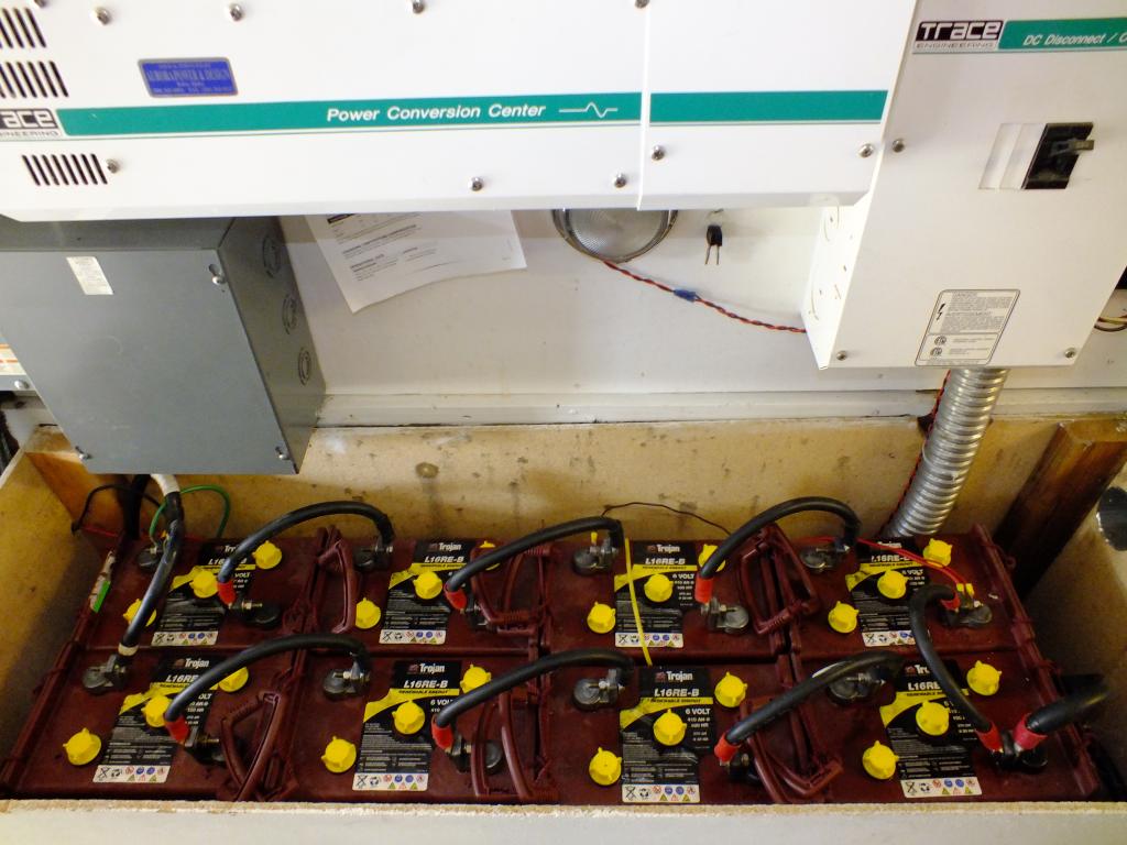
Won't matter. Still the amount of energy removed from the battery will have to be recharged back so high the CA / CCA the longer the charging time will be. Being the grids draw 195 amps max that means that energy was pulled from the battery and will have to be recharged. Larger the batteries the longer the recharge is going to be. It not the voltage on the gauge its the specific gravity of each cell. So simply put most of us just measure cell voltage. Good tidbit of info on charging. http://batteryuniversity.com/learn/article/charging_the_lead_acid_battery More about reducing the over all load... Something to think about. Just having a quick cycle of my house system because of a brown out I still got to do a 2 hour bulk charge. This is only $4,800 worth of battery nothing much...
-
So here is something to consider. 14.5 V x 60 A = 870 Watts. Now upgrade to the newer alternators 14.5 V x 140 A = 2,030 Watts of heat. So now consider the loads mainly the grid heaters hitting. Now you've got 2,000 watts of heat pouring out of the diodes. Now consider absolutely cold morning say minus numbers, weak or damaged batteries, then grid heater hitting plus the draw of the starter on the batteries. Then the alternator attempting to recover still while the grid heater continue to cycle. What do you think those minus temperature diodes are doing with 2,000 watts of current passing through them? Ah I know I got you thinking now don't I?
-
KATOOM you missed something else. You are on the right track... Being I came from the older muscle generation the older Dodge alternator were really stout alternators for their time. Now with the on set of electronic OBDII requirement for vehicles that means more electrical loads. So they increased alternator sizes. So what happens lets say one battery (passenger side) has some failed cells (shorted). So now we've got 140 Amp alternator now compared to 45-60 Amp alternators of the past. So now you have more electrical demand to even start the truck (grid heater and starter), then once it running (grid heater and all electronics), so now the alternator takes a beating so eventually the diodes get hot and start to fail. so now the noise starts to increase. Being today most everything is digital it really hard to see or hear a noise like of the old school. Back in the 60-70's older vehicles with AM radios would pick up on a failed alternator quick. So now back to the bad battery. If the battery on the passenger side is bad it not be detected for high case temperature since the sensor is on the driver side. So the alternator will continue to fight the failed battery increasing its own stress.
-
Being you are in Idaho Dynamic is just barely on the east side of Washington near CDA, Id. Since you didn't list a city I'm not sure where your at. https://www.google.com/maps/place/8311+N+Glenarvon+Ln,+Newman+Lake,+WA+99025/@45.6012254,-114.1757709,7.17z/data=!4m2!3m1!1s0x5361e783f9491d67:0x270f79fe56225493
-
No worse that the truck sitting in my yard with a dead lift pump ZERO fuel pressure and it was driven from east side of Wyoming to west central Idaho with zero fuel pressure. Still starts a runs fine so far, no codes, no problems but really does need a good lift pump. The owner is going to be getting a FASS 150. Just waiting...
-
Thing I'm worried about and since its a honeycomb styled filter it not capable of self shedding like the BHAF will typically do. so that brings up the problem of life expectancy of this filter in a extreme dust environment vs BHAF.
-
No way to install of remove the mod without breaking it into 2 pieces. So you make the rear down pipe a removal piece and and it can be easily unscrewed and removed.
-
Even after you give the Smarty back to TFaoro you'll keep the high idle setting.
-
There are no pleats as your use to.
-
Why not just have a shop do the work? Yeah it will cost a little bit o change the bearing and race but it will be better than buying entire front differential.
-
Maybe you should be here... I get better than 10 years from batteries. Like my batteries that power the house will last over 15 years if I play my card right. As for vehicles all my batteries are lasting at least 10 years. The biggest thing is bein able to do proper maintenance of the batteries once a month.
-
There is a world of difference between the Smarty for the 24V's vs. Common Rail two totally different animals and abilities.

