


Mopar1973Man
Owner
-
Joined
-
Last visited
Everything posted by Mopar1973Man
-
Yeah I got to get more pro active now on the starting rust on my truck. Nothing on the body metal but the frame is now starting to show.
-
That's just mean as hell...
-
When you replace it make sure to lightly grease the seal. It will help for future removals.
-
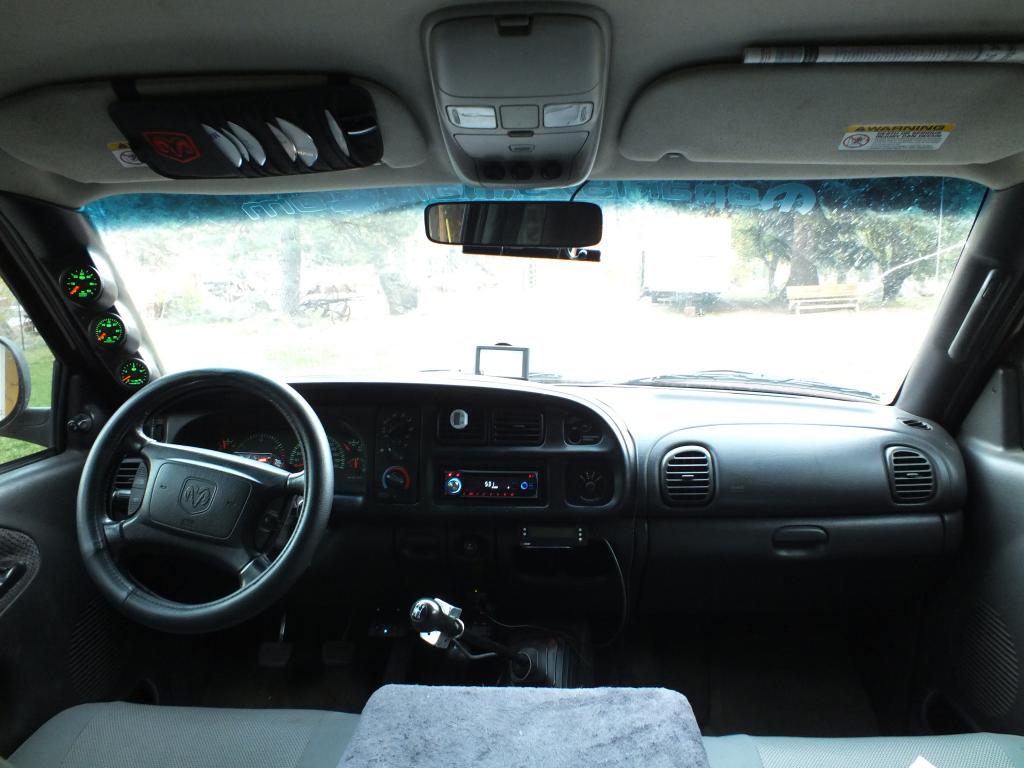
Depends... Visually mine doesn't add any width to the pillar Like my 1996 Dodge doesn't have any a-pillar gauges and the 2002 does have it and the differences are so minor it un-real. Depends on how you sit in the seat. Even the 1996 Dodge has the same blind spot in turning tight corners just because of the pure width of the a-pillar post. So take notice to my picture that the gauge pod doesn't add to the A-pillar blind spot. So just leaning slightly towards the center of the cab kills that blind spot.
-
Push lock tee, brass elbow, needle valve, snubber push to connect fitting, 5 foot of 1/8" air brake tubing, push to connect fitting, then fuel pressure sensor..
-
Won't work. You only got about 8oz tops from the pump. There is about 32 ounces in the gear box. So since you working on dillution then you need to increase the change amount to nearly 2 gallons . Most people I catch do this don't get the debris out of system as you would flushing... Kind of like doing a oil change by unscrewing the filter and dumping it out. Screw it back on and refilling a quart. It won't work. Then repeating...
-
Correct I've got the same thing too on my exhaust brake vacuum valve.
-
Correction sintered brass or bronze...
-
We need to create a article on compression testing for the 3rd Gen and the limits. AH64ID are you up to it?
-
With any fuel pressure gauge you should never hook up at the VP44 inlet. With all electric gauges they should be remote mounted away from VP44. Like mine I've got 5 feet of 1/8" air brake line to allow reduction of water hammer pulses. At the tap point I've got a needle valve and a snubber. Then 5 feet of tubing to the sensor. Mechanical naturally have this long run after the tap point and also most are direct plumbed with a needle valve to dampen. Still in all I would use a ISSPro sintered stone snubber on my next mechanical gauge if I was to do it again. I'm very impressed with their snubbers.
-
Colors have to be careful with because if the shirt color is right I can eliminate on color and reduce the cost of printing the shirts. As for front or rear we can pick or maybe vote on it.
-
I've got the switches but no cables.
-
Nothing like a plane... You can't just pull over and call for help. That would be rather spooky. My fears... Lightning Heights or falling Small spaces, confinement, entrapment (don't ask me to spell that...)
-
In a nutshell what you do is unhook the return line from the pump. Cap the nipple on the pump that you pulled from. Route the return hose to a waste container. Now with the front axle jack up go lock to lock till it pumps the old fluid out. Then refill as needed. If it not willing to pump this method. Then do a lock to lock a few times to purge the gear box out the start the engine and pump it through this will take just a few second so be ready to shut off. Then refill and do the lock to lock some more hoping to move fresh fluid through the gear box. The steering gear box holds nearly a full quart of fluid so typically a flush will take 3-4 quarts to flush the system out. Then when you happen with what's coming out of the return hose is clear then hook back up the return line and refill and purge the air out. If the fluid is foamy (which it is typically) leave it sit for a about 30 minutes and then top off again. This is why I suggest petroleum power steering because a gallon of petroleum power steering fluid is like $20 bucks where synthetic is better $100 per gallon. So more people that which to synthetics tend to have more failure due to holding on to the fluid too long because of cost. I rather change often and keep following my current path of trouble free service!
-
Thing is that analog gauges are the quickest gauge to read. Like I've got the ISSPro EV2 gauges as well. Thing is that I'm never really looking at the gauges I can see relative position of the needles and know if things are normal or not. Digital gauges like my ScanGauge II you have to physically look right at the ScanGauge I read the numbers and see if there is a rise or fall. Where on analog gauges again you really don't have to look directly at them but you can see the needle movement up or down the scale. Now with like Tfaoro phone setup that big analog gauge is easy to read but the smaller digital gauges tend to again require more visual time to see trends on the gauge.
-
Time to clean that mess up...
-
I don't know why they never came out with a 4 position a-pillar? There is enough room for a 4th gauge at the top with a modified angle adjustment. Most would get some sort of phone holder and mount it to the dash some how. I kind of want to set up my Azpen Tablet for gauges from my OBDLink LX and have both a analog gauge as well as digital. Analog is much easier to read.
-
Spider and snakes don't bother me much. Spider you just smash with a kleenex. A snake you grab a shovel take its head off. I remember one morning a girlfriend woke up and go to the bathroom and found a very large worm as she called it in the bathroom. It was a rubber boa snake picked it up, chucked it out the front door. We've got Garter snakes all over here those are harmless but nasty stink. The put off a scent that you can't wash off. No real rattle snakes where I'm at. Down in Riggins, ID there is but most are quick to clip the heads off. Spiders we've got brown recluse, hobo spiders, daddy long legs, several type most are poisonous but never had any issues with just crushing them and moving on. So the whole fear of spiders and snakes not really for me...
-
I carry tools in my truck for all the other broken trucks on the road. Like my truck is parked in the shop with rear driveshaft removed because it didn't feel right on my last long trip. Now it going to get fixed this week. I don't let things that don't feel right or look right stay I get after the problem quickly. So I'm not one of these guys that carry extra lift pump, VP44, and tools in the truck. Also that why your MPG is lower hauling around a big tool box full of your Voodoo chicken bone tools.
-
Problem is not so much the artwork. That I got a fair quote on be done. The problem is making an order of shirts so if I order say 10 of M, L, XL, XXL, XXXL I'm looking at a good sized bill for product then there is no promise that I can sell them. Bad part is we are hung up with the high idle cable right now and I really can make any more moves till I get the cables and get some sales going. Take a peek at donations there is only $70 this month in donations. So paying site bills come first.
-
I remember looking at some of AH64ID tune graphs and seeing the CR engine timing more so retarded than anything. So a tune of some sort does optimize the engine performance.
-
I want to do the shirts but I'm not seeing much for the sticker sales... I was hoping to see better sales of sticker and badges. Kind of hard to drop serious money on shirts if having hard time getting rid of only 10 stickers.
-
LOL... Mine hang out about 1.5" and I got 235's...
-
Take a look where I mounted my Scan Gauge...
-
Not a good sign to have to keep tools, grease guns and supplies in the truck.

