
IBMobile
Staff
-
Joined
-
Last visited
Everything posted by IBMobile
-
Are you using a relay to power the FASS pump and if so are you using the power led from the ECM to the old lift pump to trigger the relay or that fused wire from the ignition switch?
-
Here are 9 of them with in 50 miles of you. https://www.lkqpickyourpart.com/locations/?zip=92374&range=50 You're can call them but they might not have an up to date inventory sheet. I just go in with list and a box of tools I think I'll need. You can walk the yard, hit or miss, some times you find gold other times it's just exercises. A lot of parts from a Ram 1500, some from the derange and vans will fit on the ram 2500 and 3500.
-
There is always Pick Your Part. Great place to practice part removal also if your not sure how something comes apart.
-
Check the voltage out put of the alternator when the grid heaters are on. I've seen it as low as 11.95V when testing. Your alternator output may be low enough to trigger the apps low voltage when cold. There my be some extra resistance, dirty/poor connections, in the systems exacerbating the problem. Have you done the W-T wire modification?
-
You're in our thoughts and prayers.
-
Check all your hoses and fittings for leaks and damage. If your heater/vent ducks operate then you know the vacuum pump, hoses and fittings are good to the firewall. Old fittings like this will leak. They can be replaced with a length of vacuum hose slid over the plastic line.

-
Remember, the customer is always right. Tell them "OK We know the front brakes are shot and that may be the noise you are hearing so let's fix what we know is wrong first. Since the front brakes are in such bad shape I suggest inspecting the rear brakes also; we may have to do both front and rear brakes. What do you think?" This puts the ball in their court Could that clicking noise at slow speed turns be an outside C/V joint which is just behind the brake backing plate?
-
I had 265/75-16 and changed to 245/75-16 a few years ago when I got a deal on 5 almost new Michelin tires and have not corrected the speedometer so it read about 2mph high. With that said, below truck is going down the other side of the 6% Conway grade in torque covertor locked up 3ed gear. Cruising along in lock-up O/D A little slower Yes it does. When the APS goes to idle the PCM unlocks the torque convertor so anytime you engage the Pac Brake the controller grounds that orange/black wire commanding lock-up in idle. The 'mystery switch' will keep the convertor locked all the time it is on. If the mystery switch is on and you engage the Pac Brake then the orange/black wire is just grounded in 2 places. The DTT voltage regulator will not effect this lock-up. The regulator is used the fool the PCM about line pressure.
-
Spray the fittings with PB Blaster, Liquid Wrench or some other quality rust penetrant; WD-40 is no better than using diesel fuel and it may work but takes longer. Be sure to use tight fitting flare wrenches on the brake line fittings. The hard line fittings like to round off so take your time. After the hose is replaced you may only have to bleed that caliper. If the peddle is still soft then bleed the whole system starting at the right rear brake. Good luck and Happy New Year
-
Good luck to you and a healthy, happy, prosperous New Year to our members and their families.
-
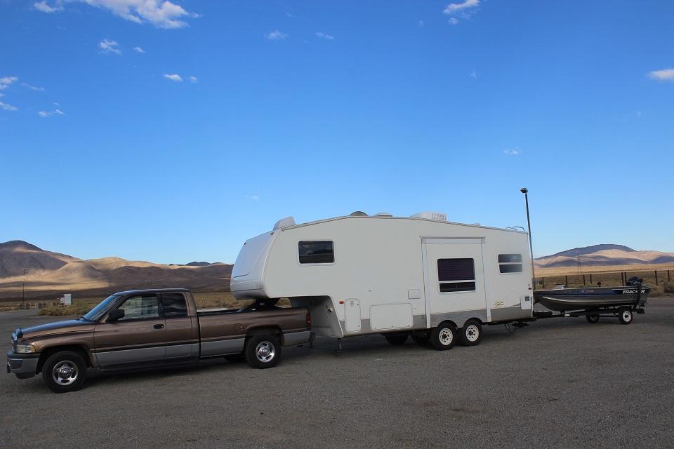
I've had both bumper pull 24' trailer with a class 5 hitch and 27' 5th wheel; I prefer the 5th wheel. The ride comfort as well as the stability of the 5er is superior to that of a bumper pull. So, consider the pros and cons of both then make your purchase, that's why they still make both.
-
Do you have a DTT Smart Controler or an ATS transmission controller? If not then this should work in conjunction with the Pac brake. They work by grounding the orange/black wire at B11 of the PCM which commands torque convertor lock up.
-
I would have told them to fix it right or I'd walk away from it. You don't want to fool around with a safety idem like brakes. Peoples lives are on the line and your liability. Years ago I had a car with a leaking front brake caliper. The owner asked me to "pinch off the brake line" going to it. My answer was "No, I don't think so". I left the car the way it was and they could get someone else to do it.
-
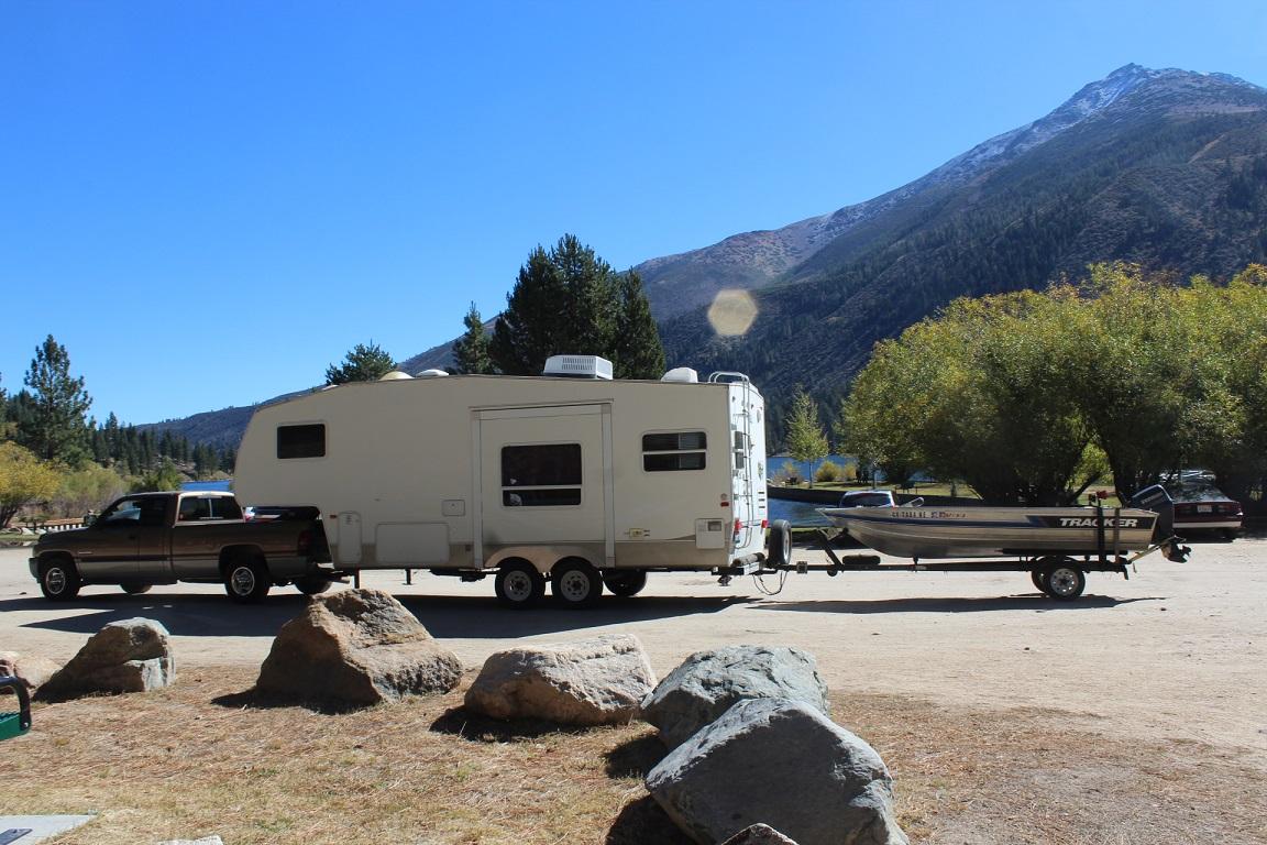
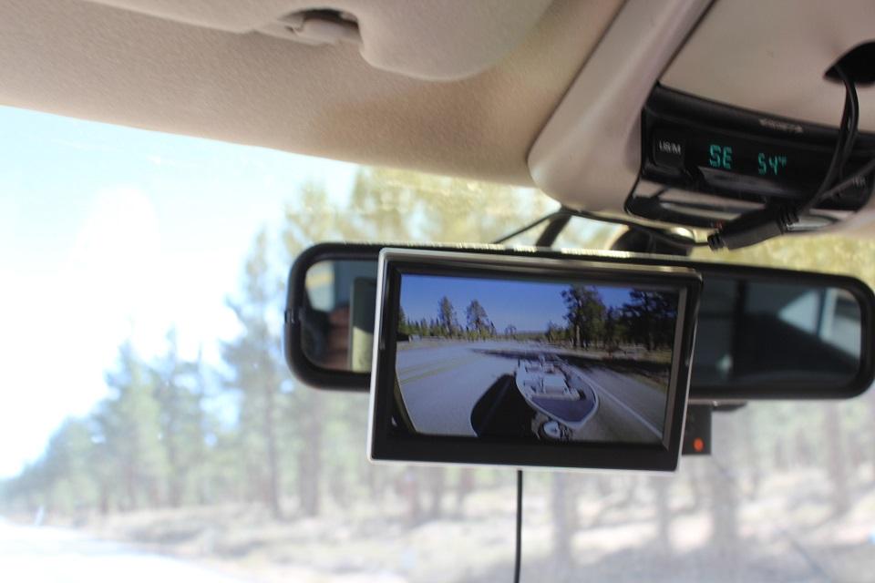
I was nervous about pulling the boat behind the 5th wheel and not being able to see it. I looked all over the net and came up with this. I also use it with just the 5er. You can see if someone is behind you, see when your trailer clears the vehicle you are passing or what's behind you when backing up. I've used this camera/monitor set up for over 300 hours with no problems.
-
I did it with my own version of a 'mystery switch'
-
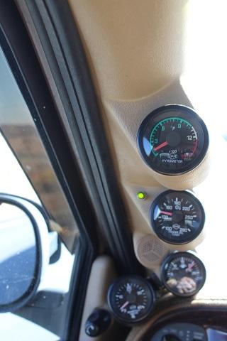
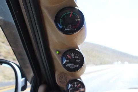
The gauge is good. I've seen it go over1200° with the trans locked in overdrive and my foot to the floor. With the transmission locked in 3ed and 55mph the exhaust temp will fluctuate with the varying grade of the road, which we have all experienced but will stay under 1000°. . The road grade that picture of the gauges was taken on was south bound US 395 between Bodie RD and Virginia Lakes RD on October 9, 2018.
-
Right you are @NIsaacs,clean air flow means no blockage from, say, crankcase breather oil and dirt. The ambient temp was around 58°F at the bottom (4,000') and 54°F at the top (8,000'). The pyrometer thermocouple is pre-turbo. I have a fitting in the head pipe for post turbo temp if I need know.
-
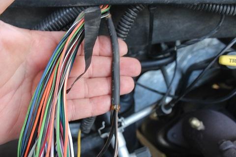
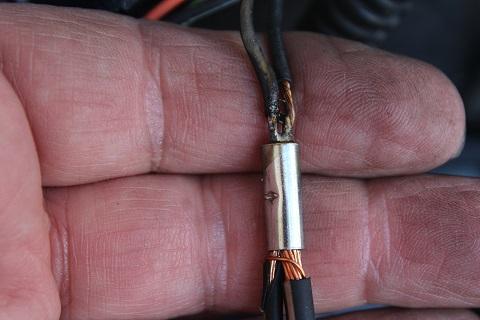
I put this together with camera screwed to a small piece of plywood, about 2"x3" painted black, an stuck inside to the trailer's back window with two sided tape, https://www.amazon.com/Esky-Reversing-Perfect-Waterproof-Universal/dp/B07KW5XQRJ/ref=sr_1_5_sspa?ie=UTF8&qid=1546148783&sr=8-5-spons&keywords=esky%2Bec170-11%2Bbackup%2Bcamera&th=1 cat5e wire https://www.homedepot.com/b/Electrical-Wire-Voice-Data-Cable/Cat5e/N-5yc1vZc5a2Z1z0uk5l?NCNI-5&searchRedirect=50+ft.+cat5e+cable&semanticToken=210r10000+>++st%3A{50+ft.+cat5e+cable}%3Ast+cnn%3A{0%3A0}+cnb%3A{0%3A0}+pt%3A{cable}%3Apt+rt%3A{cat5e}%3Art+qu%3A{50+ft.+cat5e+cable}%3Aqu The cat5e wire has 4 pairs of wires. I soldered the camera's power, ground, signal and shield wires to the 4 pairs of cat5e wire with heat shrink to seal. The cat5e wire was then run the length of the trailer and run out the front next to the 7 wire trailer cable. https://www.oreillyauto.com/detail/b/towing-solutions-3935/agriculture-hd-parts---accessories-19818/fleet---heavy-duty-20088/trailer-plugs---brakes-20099/trailer-connector-wiring-adapters-18814/4a93e97f1ed1/hopkins-towing-solutions-wire-connector/48295/4379674/2000/dodge/ram-2500?pos=25 A round 4 pin trailer connector was used to connect the 'video cable' to the truck. More cat5e was run under the truck up the firewall and through the grommet on the left side up the left A post to the over head where the connectors for the monitor were solder together along with an on off switch for the system. The system uses very little current so power was taken from the hot led for my 'mystery switch'. E-KYLIN 5" car monitor https://www.amazon.com/Monitor-EKYLIN-Suction-Mounting-Bracket/dp/B01FF2X1BW/ref=sr_1_5?ie=UTF8&qid=1546149220&sr=8-5&keywords=5"+car+monitor
-
It's amazing how one thing like a micro burst can add hours of worry and days of work. I glad thing are turning out OK for you. That a nice looking trailer and good luck with it. If you tow anything behind the trailer I suggest you put a camera in the 5er to keep an eye on it. I've got one for my boat trailer I put together, hard wired for about $75. It's also great for backing up or changing lanes.
-
I also have the EZ and the RV275's but with a 4:10 and 245/75-16 with a 47RE. My 5th wheel trailer is 8k and some times I put about another 600 pounds behind that with a 14' boat, motor, gear and trailer. I tow all over: from the flats of Des Moines, IA to Jasper in the Canadian Rockies. On the flats overdrive is on and locked up with cruise control set at 65mph. When going up a long 6% grade I down shift to 3ed, the torque convertor locked up with my 'mystery switch' and the cruise control set to 55mph. I still have peddle left to go faster but why push it and abuse what's going to get me there and back. The fan clutch an a clean air flow over the radiator keeps any overheating problem at bay. This is what my gauges look like after going up a 6% grad after a couple miles and still going up. The exhaust is at 850°F, fluid temp exiting transmission is160°F, fuel pressure at 20psi and the boost is 20psi. The green LED light tells me the convertor is locked with the 'mystery switch'.
-
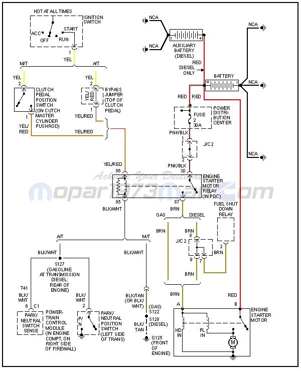
Welcome to Mopar1973Man forum. Below is the wiring diagram for the starter motor.
-
I used a piece of 4" diameter white landscape drain pipe.
-
Did you have to show him what a hammer is for?
-
@JAG1 hasn't been able to log on to post due to computer/internet problems so he asked me to due it for him. From JAG1: W-T' called me just before Christmas and asked to have a post or thread put up about his situation with the fire in Paradise, Ca. He wants to let everyone know he is okay. His house only suffered about 15 k in damage on the back side and is heat damage only as nothing really burned. The windows are melted, glass is broken, Siding everything on that side of the house is either cooked or showing heat damage. His two garages however, were completely destroyed. One of the shops, I think 1800 sq. ft. was the one with every piece of electronic equipment inside and is now gone. Months ago he sent pictures of his specialized tech equipment consisting of an almost entire wall, a lifetime collection , some custom built to his specs. We didn't have enough time to talk much further about how he saved his truck which also was stored in there. It was an expensive shop with hepa filter system maintaining a dust free clean room in which he also stored his beautiful second gen Dodge. He says that truck never had mud under the fenders, but now has ash and mud everywhere. It was better than when they were brand new on the dealer showroom floor. This particular shop costing over 200k to build originally is now gone. One thing he needs help with if anyone wants to start a discussion, he needs thoughts/ ideas on what to do. It is dilemma of whether to rebuild and stay there, or just fix the house, maybe rebuild one garage and list it on the market. Insurance is going to take care of him and is not going under from claims, but the thought is because the whole town is gone, burned and ugly with clean up taking years, the idea of moving to a new area may be the smart thing to do. Please join in with your thoughts... Thank you Daniel for your help getting this up on the forum... 'Billy' needs advice JAG1
-
The PCM grounds are the black/tan 14 AGW at C31 and C32. They are spliced with the black/tan 18 AGW from the datalink connector and another black/tan wire that is not used. These all join at splice S126 to a black/tan 10 AGW. It goes to the gray connector, which I think, you have removed at the right battery. When I did the ground modification I soldered all those wires together. I