


IBMobile
Staff
-
Joined
-
Last visited
Everything posted by IBMobile
-
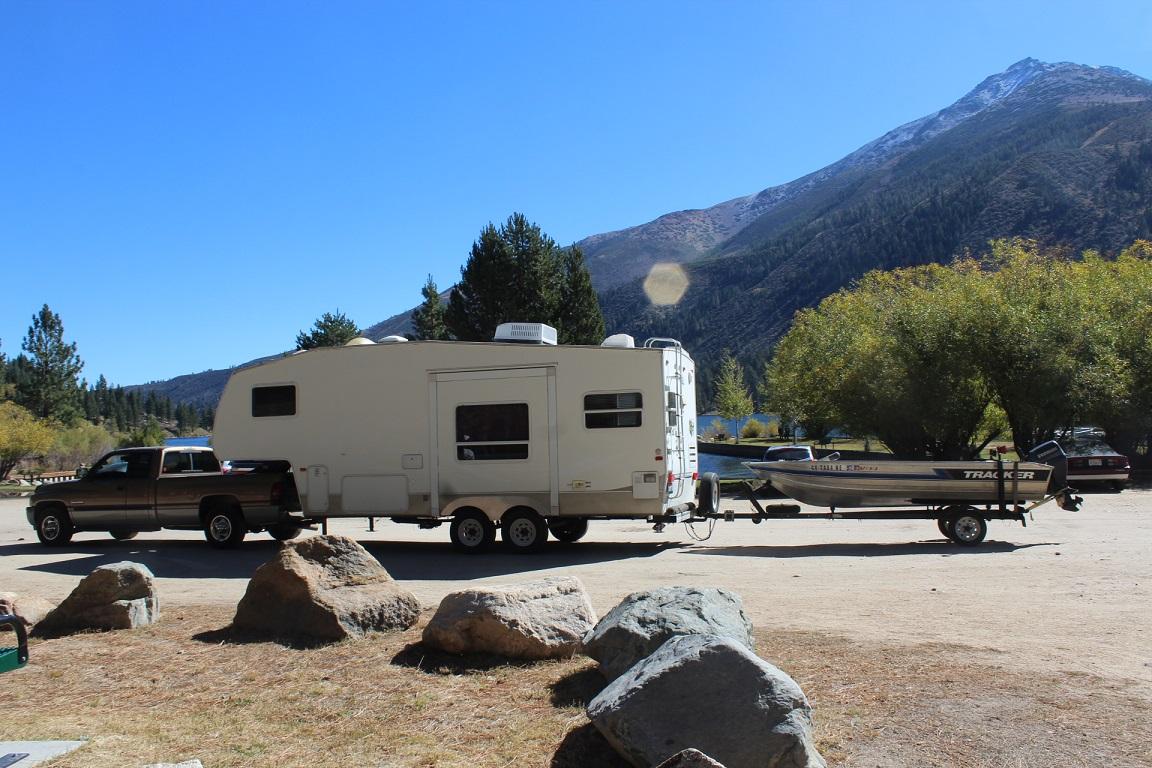
Has anyone tried with the cover off installing the seal with a press or even a C clamp? Using a piece of wood to support the housing and spread the load and a large socket to fit the circumference of the seal place it in the press or C-clamp and tighten till flush. By doing this you're not beating on the seal with uneven pressure which could cause it to deform and it should go in straight.Here's the NADA and RTV web sites for price checking. Remember, these are only price guides and actual value my differ due to supply and demand along with condition and options. http://www.nadaguides.com/RVs http://www.rvt.com/price-checker/?searched=trueI found out the original fenders were just slapped on at the factory. The right side had a 1"+ variation between front and back, never noticed it before. I found the center line between the axles and the center line of the new fender, measured down 1½ " from the molding above the wheel wells, drilled and installed. I think trying to hammer a curve into it with out knowing the radius, having a jig and annealing it would be a bit hard to do. Now I have a sheet 28" x 96" left that I'm going to use as a rock shield on the lower front part of the 5er with more pics to come about that.
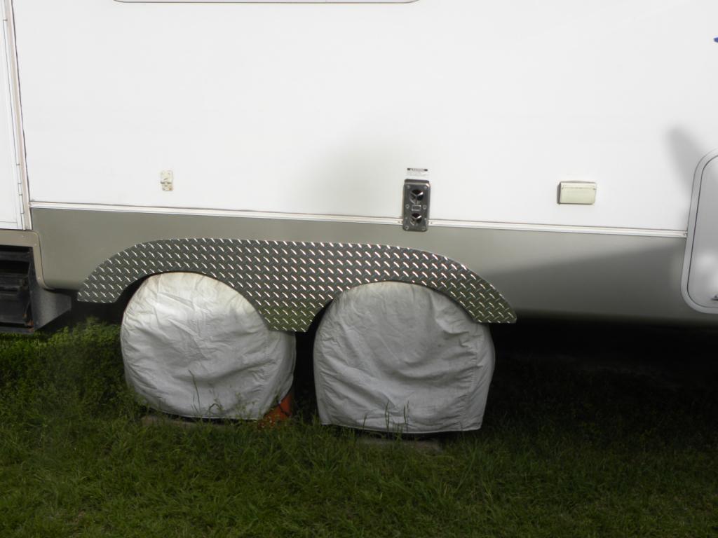
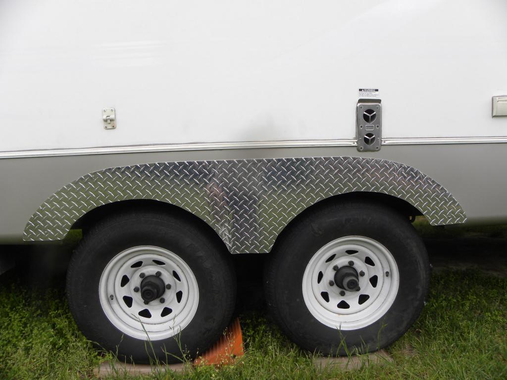 Go to the Articles, click on 24 valve 2ed generation, click on transmission and transfer case, now find the write up at the bottom called torque converter lock/unlock issues. This is a good place to start.RVs' value drop faster than a squirrel falling from a tree. The RV dealer will tell you one thing on the phone to get you to haul it to his place and then low ball you hoping that you won't want to drag it back. I put my set-up together because my wife likes to do day trips and take pictures. I like to fish and she doesn't. Now she only goes camping if the grand kids are with use or we go some where new. It's hard to tell what the future will be but the value of that toy hauler isn't going up so unload it PDQ. When you're ready to get a new set-up reevaluate your situation and think of how it will work for you 10+ years out, as you can see things change.Got that sheet of 3003 aluminum today at 12:30 and had the fenders hanging by 5:30. Cut the sheet down to 20" x 96" on the table saw using a fairly new carbide blade. Thanks Driply ! Did a lay out to maximize material Make a copy and cut that one out. cut out and the edges sanded with 220 grit paper in a palm sander One side installed temporarily. Now the top of the fender is lined up with were the original fender was but the original fender curved under the body and I can't bend the aluminum to follow the curve with out heating it. I'm going to raise the fender about 1" until the bottom is even with the trailer body. That should finish it off.
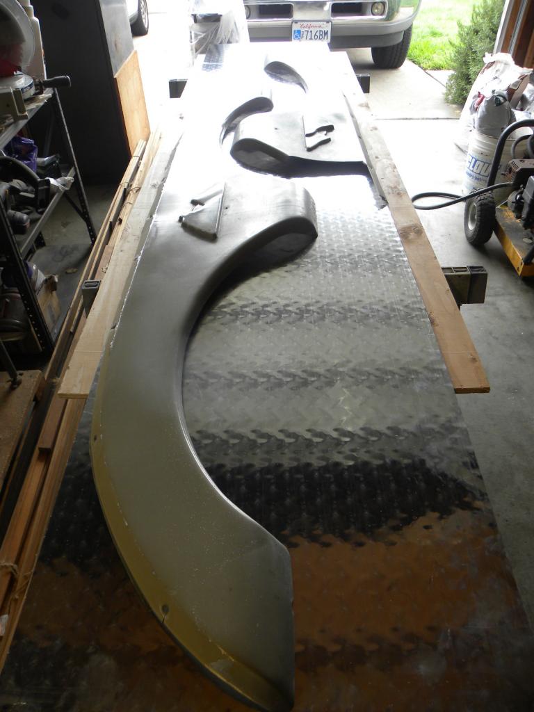
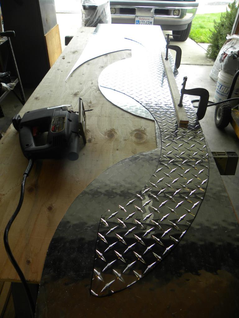
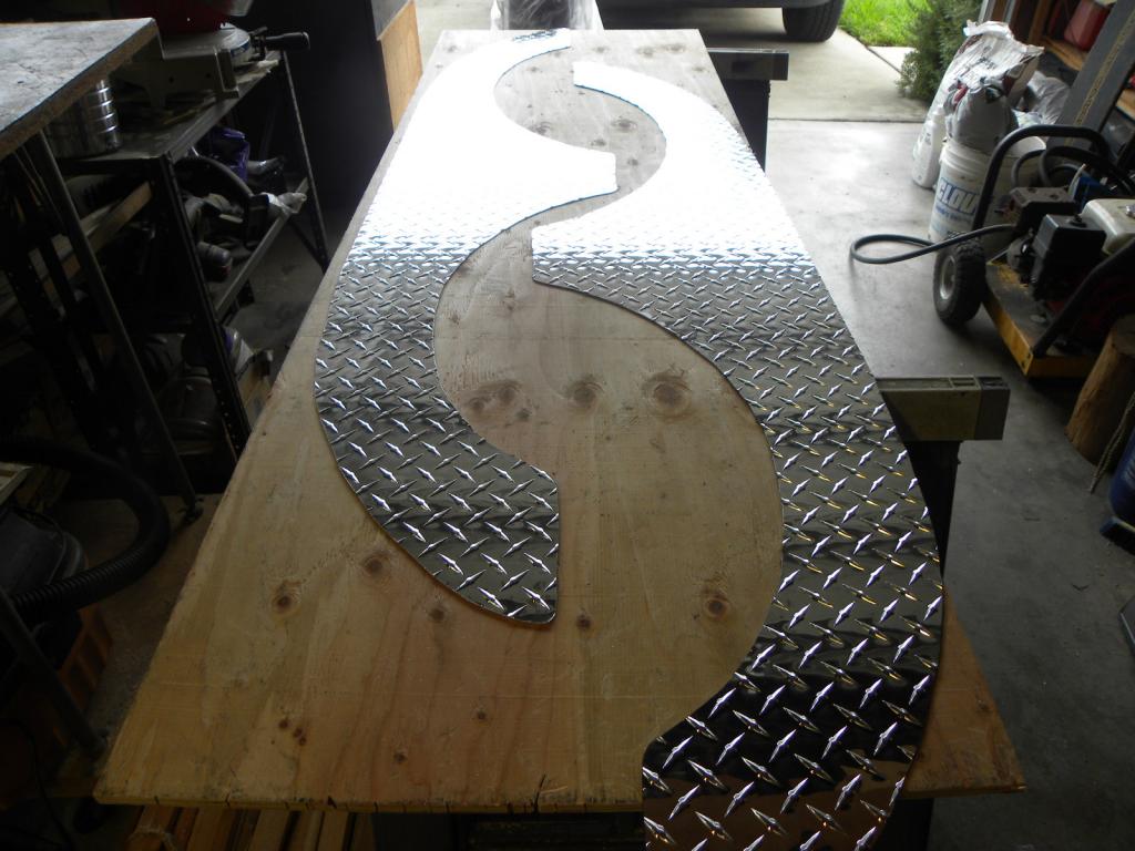
 Try this get a 1-2" sheet metal screw, a #8 should do and the longer the better. Now drill into the broken crank sensor with a drill bit a little smaller that the screw, about an ⅛" bit, Put the screw into the sensor and with a pair of vice grips you can hopefully pull it out.With the key in the off position pull the relay out and find terminal 30. Now with a test light or volt meter set for 20 volts DC test the corresponding plug. If you have battery voltage there then the rely is wired direct to the battery. If there is no voltage turn ignition on and test again. if there is no voltage then it is most likely wired backwards and you'd find voltage at the wire for terminal 87.Pull the relay out and start the truck. If you have no fuel pressure than that's the relay.Since the use of fire in a cave man has been using wood for heat and to cook. In that time humans have learned how to safely vent the byproduct gases and particulates. If you did have a leak in the stove or vent pipe in the room/house then you would have a high level of CO gas.I charged up the battery for the camera and will take a few pic of the process. I'll probably start this project the beginning of next week. I've got a Delta Contractor Saw with a 30" Unifence and plan on using an old carbide blade. Since the material is .063" thick putting the blade about .25" above the deck should give a clean cut. Any thoughts?Well the Boss gave the diamond plate the go ahead so I went to two metal supply venders today. The first place had it only in 3003 aluminum 48"x96" x.125" for $186. The next supplier had 3003 aluminum 48"x96"x.063" for $110. I think that .063" will work just fine. I should be able to cut it down to the 12"x72" on my table saw with a carbide blade and do the radius cuts with the jig saw. I might put the rest of the diamond plate as trim on the front of the 5er.I was up in that area last spring towing my 8,000 lb 5er with no problem on a stock turbo with an Edge EZ and a boost elbow. I had no problems go up or down the mountains.Never, ever put a bigger fuse in to test for a short circuit. The wires will heat up and burn thing around them before the fuse will blow. I had to fix the aftermath of an electrical fire because someone put a 16 amp fuse where an 8 amp went.I like the idea of diamond plate. I'm thinking 3003 aluminum @ .025 thick, each side 12"x72" and trimmed to fit. Now I have to run it by the boss and see if she likes it or not.Not so fast Kemosabe. The special California can has a valve in the top that shuts the flow off when the can is disconnected so you can put in what you want and save the rest for later. You need to use the thread on adapter to mate the can to the A/C gage fill hose. If you live in CA you get to pay a $10 a can deposit and if you don't turn in the empty can in 90 days you loose the deposit, the state keeps your money. I bought a case of 134a cans in Las Vegas, same cans as in CA but no deposit required. I use them now for my refund.How about dumping a can of this in?http://www.oreillyauto.com/site/c/detail/INTC/R134AUV12CA.oap?ck=Search_134a+with+uv_-1_2902&keyword=134a+with+uvHe left off how to quiet a throttle rod knock or spin a Johnson rod bearing.Last time out with the 5th wheel the right side fender decided to customize itself. I was wondering if any one else has had this happen and what they did or have an idea. New replacements are $150 each which I think is a lot for molded ABS. There is aluminum trim fenders for $90 each or rubber trim for $50 for two. One other thought was take the other side off and have fiberglass copies made by one of my customers that glasses surfboards. http://www.icondirect.com/keystone-5th-wheel-travel-trailer-fender-skirts-fs710/ http://www.trailer-fenders.com/tandem-axle http://pacerperformance.com/products-footer/flexy-flares/universal/no-lip-side-mount/led-smoke-hi-5-cab-roof-light-kit-88-02-gm-style-detail
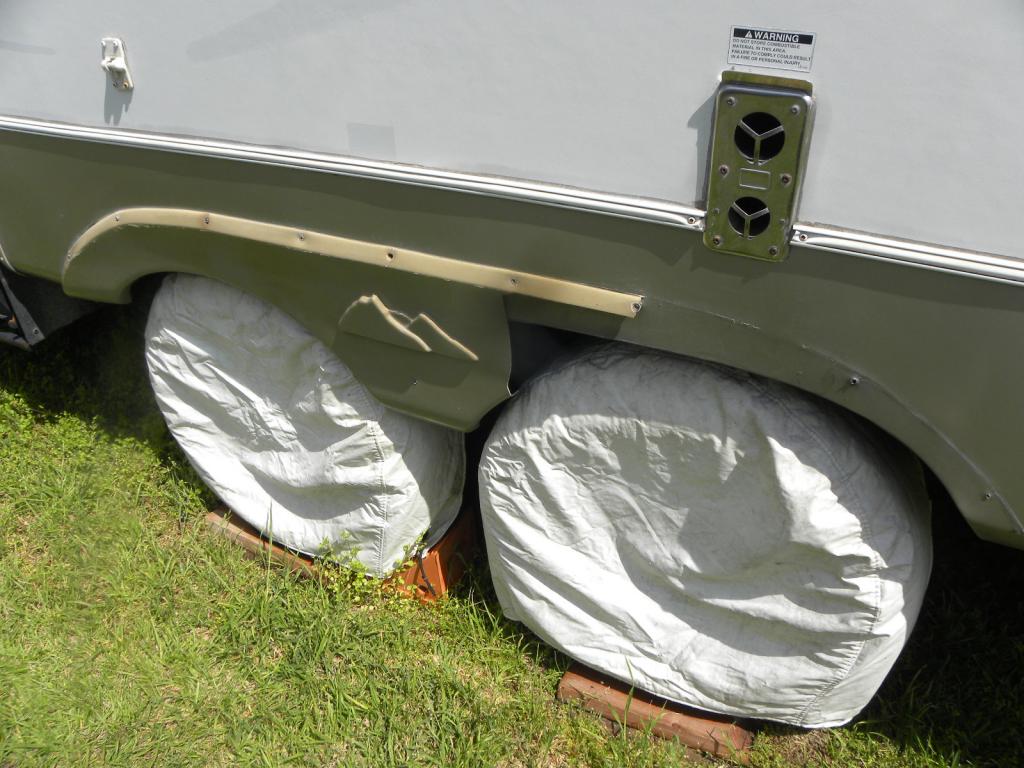 This web site has several web cams at different bird nests. You can waste a bit of time watching an eagle feeding it's eaglet or may be not.. http://www.decoraheaglecamalerts.com/All of last year (1-1-2015/12-31-2015) my truck was driven just over 4,000 miles and the batteries are fine. If you're worried about a lead sulfate problem the truck would have to not run for months at a time. Driving the truck around a few times a month will keep the lead sulfate problem at bay. Don't do a short drive/idle cycle, the battery will further discharged and the alternator can not fully replace what's been taken out by the starter motor. Batteries naturally discharge over time and sitting in a vehicle with a patristic drain does not help. If you add high temps to the equation, 77° or higher, a battery will go flat that much quicker. Lead sulfate crystals will coat the plates and harden. When this happens the battery's ability to recharge is impaired and it's load capacity greatly diminished.with that terminal clamp cracked your basically running on battery. Think of it this way, if the nut holding the cable to the starter motor was loose how well do you think the starter motor would work. You can buy battery cable ends at any auto supply store for an interim fix until you get that cable replaced. Order a new one or find a battery supply house that also makes custom cables or make them your self. http://custombatterycables.com/application/dodge_ram.htm https://www.youtube.com/watch?v=TlEUqZSyo4I I see that the battery was manufactured in12/2012 so it's 3 years and 3 mo. old. The installation date tag was never punched out but batteries are usually installed within a couple of months of being produced.Had the same problem a couple of years a go. I replaced the starter and all was good. The contacts in the starter solenoid were bad causing the starter motor to turn slow. Another year it was low voltage/amperage in the batteries causing the same problem. These engines like to spin fast making compression to fire off.When backing up into a tight confined area, especially at night I use 2 way radios. I put one on the dash and have my spotter talk me in with the other. Think of it, the back end of that trailer is 40' from where your sitting.

