


IBMobile
Staff
-
Joined
-
Last visited
Everything posted by IBMobile
-
Thank you for the heads up. No, not yet. A PacBrake set up would cost over$1700, A BD e-brake is over $1050, and a Banks e-brake is over $750. I just spent over $3,900 on a transmission and will be spending over $1,000 for a new RV roof along with another $1,000 for a 3 week trip. So, unless I find a killer deal on a new/used one this project is going to the back burner for now.
-
Went to the Hillcrest area of San Diego this morning with my wife driving. No traffic; it was lighter than a Sunday morning. I had to tell the driver to slow to under 80. The California Highway Patrol was all over the I-15 doing a max enforcement. We went into the doctor's recipient area and before they would talk to us we were directed to go to another room for Coronavirus screening. Here we were asked a few questions like "have you been out of the country recently" and "how do you feel"? In her hairnet, face shield, mask, and blue gown I knew she wasn't from the INS and I wanted to say "Well, McFly, we'er here to see the Doctor so what do you think?" but to get through this I just muttered a "No and I'm fine". I went to Costco last night at 8;20. All the tp, paper towels, bottled water, bread, pasta, meat(fresh and packaged),along with alcohol, and cleaning products were gone. There was a limited amount of milk, eggs, and frozen chicken breasts. Plenty of frozen fish and other more costly items were still on the shelves.
-
Pollock, ID: Total population 270 Total population (male) 136 Total population (female) 134 Population median age (male) 49.5 Population median age (female) 51 Here in crazy land San Marcos,CA: Population in 2017: 96,198 (100% urban, 0% rural). Males: 47,578 (49.5%) Females: 48,620 (50.5%) Median resident age: 35.3 years
-
Just got back from WalMart. I went there to get some anti freeze for a Toyota i'll be working on. Out of curiosity I went to the grocery department on the other side of the store. The shelves are empty of all: soup, peanut butter, caned foods, flower, breakfast cereal, meats, cheese, milk, eggs, bread and cleaning products. Even mayo, mustered, relish and ketchup were slim pickings. I knew it was going to be spars but what I saw was as sobering as a seance from an apocalyptic thriller. It reinforced the practices of stocking food and supplies for an emergency.
-
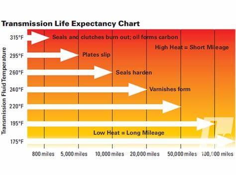
I have my sensor installed in the line between the transmission and engine coolant heat exchanger. This is the hottest you will see the fluid. You will then be able to react to the driving conditions before the fluid returned to the pan is overheated. A sensor in the pan will show the temp of the fluid being used in the transmission. There is a lag in the reaction time to temperature change. When you see the temperature going up and react to bring it down it can keep going up 5°-10° before decreasing. I have a deep pan, about 1 gallon more fluid, and the fluid coming out of the torque converter heats up just as fast as with the stock pan.
-
Remove the transmission relay in the PDC and see what happens. That will kill the power to the variable force(pressure) solenoid, torque converter solenoid, and overdrive solenoid. I think the truck will be in 3ed when shifted to drive.
-
Saul Alinsky's Rules for Radicals Rule #9: "The threat is usually more terrifying than the thing itself". Rahm Emanuel:"You never want a serious crisis to go to wast" They are a herd animal and easily slaughtered. .
-
I keep mine stocked with water and supplies incase of and earthquake.
-
Did you center the clock spring before you installed it.
-
Something like this one? https://www.amazon.com/Battery-Tender-021-1164-Maintainer-Microprocessor/dp/B004Q86JJ8/ref=sr_1_1_sspa?dchild=1&hvadid=78202816958563&hvbmt=be&hvdev=c&hvqmt=e&keywords=solar+battery+charger&qid=1584219474&refinements=p_89%3ABattery+Tender&rnid=2528832011&sr=8-1-spons&psc=1&spLa=ZW5jcnlwdGVkUXVhbGlmaWVyPUEzSE8xSDFPUzZZUE9SJmVuY3J5cHRlZElkPUEwODY2OTcxT0hTVzZBTVUwOEsmZW5jcnlwdGVkQWRJZD1BMDE1NDk1NTNVQUkyOFQ5RFRDUTcmd2lkZ2V0TmFtZT1zcF9hdGYmYWN0aW9uPWNsaWNrUmVkaXJlY3QmZG9Ob3RMb2dDbGljaz10cnVl But it would work for people, like me, who park their truck outside.
-
How about a solar battery charger on the dash when parked? You can cut off the clamps and install eye ring terminals to attach the charging wires to the battery posts. https://www.amazon.com/s?k=solar+battery+charger&hvadid=78202816958563&hvbmt=be&hvdev=c&hvqmt=e&tag=mh0b-20&ref=pd_sl_8bhrojf8da_e
-
This the #12-1/4" lug I got out of my supplies. I took the plastic cover off and opened the end to fit the four ground wires into it. They were then soldered together.
-
All the stores are out of TP here. People are lining up in the rain at Costcos hours before they open in hopes of getting a package of 30 rolls. The line to get in snakes from the door along the side of the building and through the parking lot. I haven't been able to see the connection of toilet paper and the Corona virus.
-
Could this be the torque convertor locking and unlocking you're felling? What is the AC voltage at the alternator?
-
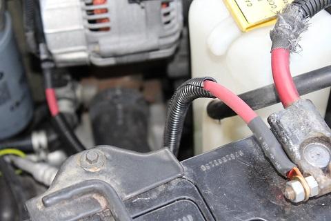
While it's off do the W-T wire modification and save yourself some headaches later on. Look this over first. This is another way to do it. This is how I did it. 1 Disconnect batteries 2 Unplug ground wirer, the one (black/yellow) that comes by the alternator, at the aux. battery. 3 Remove the charging wire from the B+ terminal of the alternator. 4 Remove alternator top bracket. 5 Remover the ground and charging wire from plastic conduit removing the 3 clamps as you go. 6 Remove the 10mm nut that holds the charging wire at the PDC and throw the wire in the trash. 7 Cut the ground wire where the 4 wires are spliced into it and throw the old ground wire in the trash. 8 Strip the 4 ground wires an solder the in to a #10-12 1/4" eye lug. You may have to spread the end of the lug open to fit all the wires be for you solder. 9 Install new 1/2" conduit on remaining wire that are in front of engine and reinstall the 3 clamps. Tape ends as you go with quality electrical tape. 10 Make the ground cable from engine to main battery. Cut #6 AWG cable 18-20" long and solder lugs on. I used a small butane torch to do this. Don't for get to orientate the lugs for minimum cable twist and slid the heat shrink on the cable before you put the lugs on. 11 Attach ground wires and cable to engine case with the 5mm x0.08 bolt an a flat washer and attach other end to main battery negative clamp. 12 Make the B+ charge cable from alternator to the auxiliary battery. Cut the #4 AGW cable 20" long slide on the heat shrink and solder on the lugs. The sides of the #4-1/4" lug that goes on the alternator B+ post may have to have its side ground off by a few thousands to make it fit in the insulator. 13 Attach the B+ charge cable to the B+ terminal of the alternator and the auxiliary battery positive clamp. Refit alternator top bracket. 14 Inspect all work, reattach all battery cables to the batteries and rest APPS. 15 Start engine and test DC and AC voltage at B+ terminal and both batteries. A battery shop has the cable and lugs. The rest of the materials, (solder, heat shrink' cable cover, #12 -1/4 lug, bolt and washer), came out of my supplies, 2' #6 AWG $5.54 2' #4 AWG $5.54 1 #6 -1/4" lug .47 1 #6 -5/16" lug .47 1 #4 -1/4" lug .47 1 #4 -5/16 lug .47 TOTAL 12.96 I added a 150 amp fuse to this cable later.
-
WELL DONE!
-
This is the latest in the government fight against the Corona Virus (covid-19). This device will fully encapsulate the head guarantying to keep your hands away from your nose, eyes, mouth, ears, or any other part of your face. This is a CDC approved protective device and will be available soon at an outlet near you . For more information call 1-800-232-4636.

-
From "BASIC AIR CONDITION REPAIR" article in 2ed generation 24 valve cab interior. Always replace the o-rings when working on an open system. They are a possible point of future leakage, and it’s cheap and easy to do. All O-rings need to be coated with A/C mineral oil NOT PAG oil. PAG oil is hydroscopic and will cause corrosion on the outside of the hose fittings and O-rings.
-
Found mineral oil here to be the least expensive. https://www.oreillyauto.com/detail/b/murray-climate-control-4379/chemicals---fluids-16461/air-conditioning-chemicals-16497/refrigerant-oil-12459/cafa2aa02793/murray-climate-control-mineral-oil/59000/4521683/1992/volvo/940?pos=0.
-
While you have it apart the accumulator should be replaced along with the orifice tube and all the 0-rings. The O-rings should be coated with AC mineral oil and not PAG oil before installation. You will need to add 2 ounces of PAG 100 oil to the system for the replaced evaporator and 2 more if you replace the accumulator. You may want to replace the fan motor; it's old and tired and dido for the heater/AC blend door coupler. https://heatertreater.net/dodge-ram-95-02
-
Thanks and get him over here.
-
Do you have to cut the stock down pipe and weld the new Banks pipe to it further down by the bell housing?
-
I remember that grade, thought it would never end. How was the down pipe to fit?
-
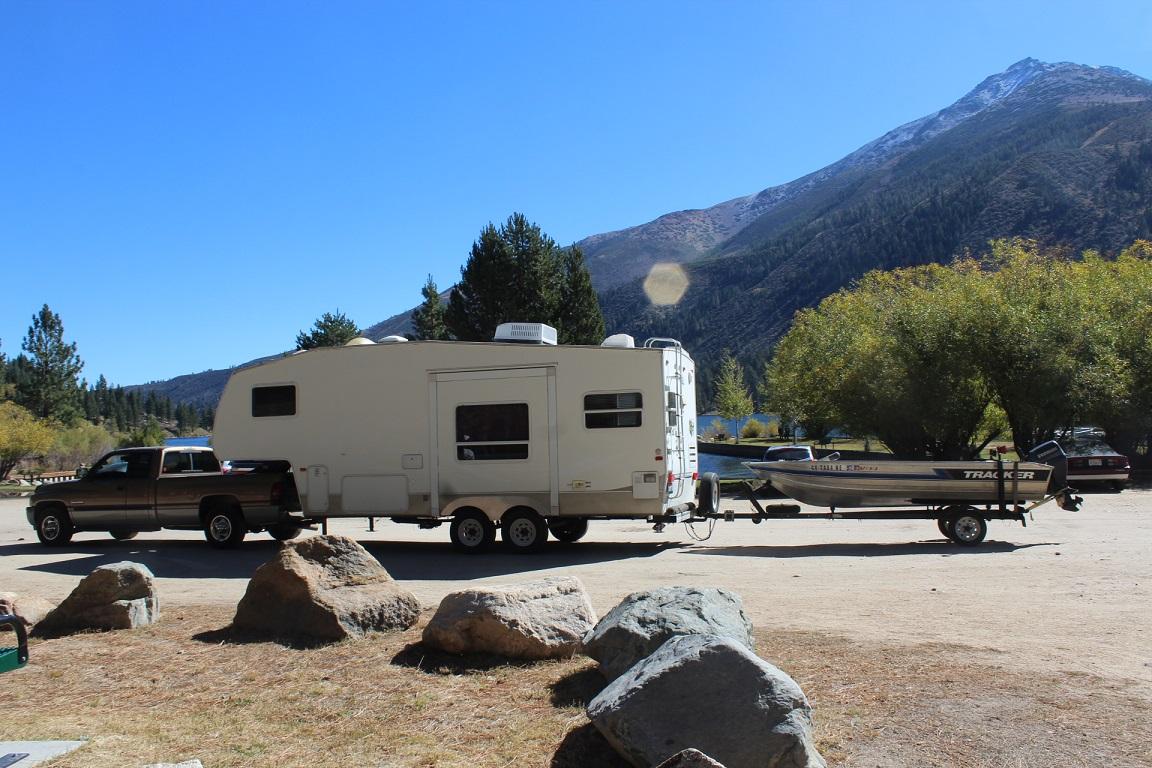
Is anyone using a Banks exhaust brake and if so what do you think of it? I'm looking for a little help in down hill braking but not something that will overwhelm the transmission. The Banks is less expensive than a PAC or BD E-brake but need to splice in there down pipe. The truck and trailer are under 15,000 pounds.
-
He didn't make it!


