Haggar
Unpaid Member
-
Joined
-
Last visited
Everything posted by Haggar
-
Ronnie, I have attached the electrical diagrams from a 2001 for the wipers. Most likely it is your multi function switch. But it could be the CTM too. There is a good diagnostic chart in the manual also. Here is a description of the operation: • Continuous Wipe Modes - The two-speed wiper motor and the internal circuitry of the multifunction switch work in concert to provide two continuous wipe cycles, low speed or high speed. • Intermittent Wipe Mode - The internal circuitry of the multi-function switch, the CTM, and the wiper relay work in concert to provide an intermittent wipe mode with multiple delay interval selections. On models with a high-line or premium CTM,the CTM also automatically adjusts each manually selected delay interval to compensate for vehicle speed. All of the power comes from fuse 6 in the panel by your driver door (called the junction block) So if any part works the whole system has the potential to work. When you turn them off do they just stop or do they go back to proper position. (this would tell us if the park switch is working.) Its odd that you lost low speed too. The power for low speed (and high speed) is a direct signal from the multifunction switch. red/yel and brown/white feed low and high speed directly ignoring the CTM. The park switch in the wiper motor is an important part. I think the CTM will never reset without seeing the park switch. Hope this helps GL Hag 2001 FSM Ram 8w-53-2.pdf 2001 FSM Ram 8w-53-3.pdf
-
Grrrr, that kinda takes out a switch problem.... Ok Since S183 also controls the relay and the FOG LAMP INDICATOR.... Does the indicator flicker also or does it stay on solid like they are working, but the fogs themselves go out? (this isn't a perfect indicator as it could be an LED... but it is shown as an incandescent so it should dim with voltage fluctuations) If it flickers... look for a problem in S183. If it stays on solid the problem is between the PDC and the lights themselves.....so we follow the Black yellow wire (that went into the Relay on terminal 87 and comes out of the relay on terminal 30 it is now LB (which I assume is Light Blue) This light blue wire will go to a splice S110 (but this is NOT our problem if the indicator light stays bright.) To connector C105 . The book says C105 is at the rear of the front bumper. no picture. (it should be close to the mounting bolts. This is a connector so the bumper assembly could be installed easily. )C105 is just a 2 wire connector with a light blue and Red orange wires in it. The red orange wire is your constant hot from the fuse G. The light blue is your ground we are following. It goes to S134. According to the manual it is a T/O the right fog lamp. I think this means that it is a tap off the right fog lamp. so at the right fog lamp you will have 2 light blue wires one of which goes to the connector C105 and the other goes to the left fog lamp. (if both of the fogs go wonkee its probably not here it looks like C105 is the issue. BUT it could be the doubled light blues in the right connector also not making good contact to each other.) Hope that helps Hag
-
Marcus, we gotta get you reading wiring diagrams..... (open up the one I attached I will walk you through it) The PDC ground is G100, G101 and G102. Those are located under the battery on the driver's side. The ground wire goes from the fender to the PDC and is split to the different circuits by Joint Connector #1. BUT THIS is NOT what you want. (if you are still looking for your fog lights wonkiness...) Ground G201 is the main ground for the headlight SYSTEM. If your other lights work ok, it is not that ground that is the problem. The ground passes through your headlamp switch in its OWN connector called C2. The ground then goes through C134. This is a huge connector that connects the dash wiring harness to the harness going to the rest of the truck. (I can send a picture of that if you need. But you can find it in the manual by looking in the connector location chart. That is probably not the problem but we can come back to it if needed) The wire then goes to the PDC and is part of a splice called S183. I don't know what this looks like, but I am betting it is three BRown/Yellow wires twisted together. (Joint connectors seem to have terminals, Splices seem to have just bare wires twisted together....) I would try disconnecting headlight switch connector C2. I would put a jumper in the connector and see if your fog lights work normally. This would prove if it is just a switch problem. If they still work poorly, I would then take the PDC apart and look for the spice S183 to see if the wires have separated. GL HTH Hag 2001 FSM Ram 8w-50-10.pdf
-
Stanley, When I put my case halves back together I use an anaerobic sealer. They are usually very thin and don't harden if exposed to oxygen. so any that squeezes into the case won't turn into a lump. I use the loctite 515, but I am certain there is a permatex version also. HTH Hag
-
digi, The FSM has both the gas and diesel in different sections. Send a Private message to Mopar1973man. I think he may have what you need. HTH Hag
-
Bullet, I have a bit of experience, but not behind a Cummins. Ford Super Duty with detroit. Loved it. BUT you must drive carefully. It was my friend's and he had it a bit hopped up. I had to be careful with the skinny pedal in the rain. It would spin easily (and i didn't drive it enough to learn when the power came on) and i would find myself going sideways but I could control it. (never had trouble now that i think about it unless it was raining...) Suburbasaurus (plural) and other GM trucks i had had the gov lock (aka timex bomb). This is GMs version of the Detroit. I love those, BUT you have to again pay attention to the skinny pedal and its application. Low traction situations will allow the one wheel to spin until it locks, then depending on traction, you will either go forward or sideways. A couple passing situations on painted surfaces allowed one wheel to spin, lock the axle, and elicited a counter steer to keep the vehicle velocity vector to stay straight. The nice thing is usually removal of the input allows it to unlock and there are no problems with trailing throttle over-steer (which is easy to have with a spool). With our torque, you won't want to slam the skinny. lightly spin until it engages, then hammer it. That is the way you have to drive the gov lock, otherwise you get the timex bomb. hth Hag
-
Dale, Hope a couple other guys chime in. But I and my brother have the same unconnected ground you have in the first picture. The second picture COULD be the cummins ECM connectors for diagnostics. I cannot find proof for this at the moment. But I swear there was a place (usually wrapped up in the harness) where a connection could be made. (I could be seeing ufos too.) Not sure on the third picture. I attached the connector locations for the drivers fender It might help you remember where it connects. GL HTH Hag 2001 FSM Ram 8w-90-18.pdf 2001 FSM Ram 8W-90-20.pdf 2001 FSM Ram 8w-90-15.pdf
-
Mike, If you lost your cad during acceleration (low manifold vacuum) all that was wrong was the check valve before the vacuum reservoir was bad or missing... that is an easy fix. Don't let that be a detriment. (beats the early GM heater type actuators) Merry Christmas all! Hag
-
I have a lift too... Its still not fun. The angle the rear axle droops to makes it a pain to put the carrier in and out for the pattern testing. (dana 80 carriers are heavier now than they were when I was 20yrs younger...) the angle also makes the pinion bearing outer races harder to get to. Turning jumping is normal on a hard surface. (this is why i have the CAD disconnect in for 4 Lo backing. Reason i asked, I know 3 vehicles that somewhere during their lives, the front ratio did not match the rear ratio.... bad mechanics axle swapping without thinking? intentional pains in the butt? totally unsure. but those would buck and hop in a straight line. GL Hag
-
To verify your new ring and pinion ratio, just open the cover. Count the number of teeth on the pinion. Count the number of teeth on the ring gear. Divide the number of teeth on the ring gear by the number of teeth on the pinion. This is the gear ratio of that pair. It is certainly possible to get the 4:10 with the 5 speed. I am sure it was an option. Axle swap would still be faster. Its better to have the axle out to get the gears set anyway. (its not fun under the car doing the ring and pinion. it can be done, just did my brother 70U, but in hind site i should have dropped the axle. I am like mike, the LS is not needed, but nice. Hag hops and bucks in a straight line, or only when you turn? Hag
-
Mike, I have been pondering this for a few days. There is no true explanation for "why now". The load of the grids doesn't go directly to the alternator. It is buffered by the batteries. Yes the alternator has to eventually recharge that, but it doesn't go bananas. (or just as bananas as your starter which pulls more...) What you/we might be seeing is the reduced quality of some of the electrical components..... I am seeing it a lot in capacitors... They just are not the quality that they used to be. I am somewhat seeing it in resistors also. They just won't carry their rated load for any extended period of time. (though they used to...) I don't know the manufacturing process for diodes. But if the same manufacturing process and materials changes are similar in those to what has happened to capacitors and resistors, it might be this problem. Just my thoughts, no proof (on the diodes anyway... capacitors I can show you many examples...) Hag
-
The stock check valve does have a small bypass. HTH, Hag
-
External pumps. I know NASCAR used an external pump and cooler for the rear differentials. (I am guessing most of the offroad racing and endurance type racing are using it) I know before the race, they ran heaters to bring the differential oil to running temperature (and engine and transmission oil too) The cold fluid's thicker viscosity sucked too much horsepower to heat up to be competitive. In the Datsun we raced in SCCA, for enduros, we had to watch transmission and rear differential temperatures, but the class we ran in didn't allow us to run extra coolers for those items. So it comes down to "how hard do you push it?" Just monitor your temps, and if in your "normal" situations you are getting close or going to hot, the first thing to try to add is more oil capacity. this will extend the time before you get too hot. If that doesn't give you enough cushion, add dedicated cooling to the system you have.
-
I always use distilled water. Our county water has a high level of chlorine added. (kinda messes up the avoid chlorides part) and our well water has a lot of sulphur (messes up the avoid sulfates part....) and other heavy metals and minerals. so I am better off using distilled and watching Ph. Hag
-
015, I use foxit reader pdf printer. (I don't use adobe acrobat or a built in browser plug in to view pdfs.) (it is the orangish /yellowish version. the purple is a payed subscription but has tons of features) this gives me the flexibility to send pdf pages to a printer or just as easily to a file as a pdf. The foxit pdf reader i am using is the free version, so I miss a lot of the options of being able to edit them and such. If you do it often or have need for it, it is a great way to do it. I backed into it through work mainly. Our tech manuals for the equipment we produce, I make a manual for the customer. I keep copies of all of those by serial number. So in a couple years when the customer calls and asks a question or emails, I can grab the exact page from their manual and send it back to them. If i need to circle something in it, or draw a red arrow to point to where a possible problem is, I open it up in foxit, but then use the snipping tool (on all windows 7 and newer machines by default) that will take a "photo" of what is on your screen and save it as a Jpeg. I can edit the Jpeg with paint and resave it with my edits on it. HTH Hag
-
I agree it is odd. They are not really related on the ground side..... They share the same fuse, but radio and other obvious stuff shares it. The only thing they share is C203 a connector after joint connector 5. HTH Hag 2001 FSM Ram 8W-12-14.pdf
-
take a peek at these. 2001 FSM 2001 FSM Ram 8W-15-16.pdf 2001 FSM Ram 8W-44-4.pdf 2001 FSM Ram 8W-62-2.pdf
-
Mike, In my manual on 8w-44-4 the center dome lamp is shown as using G201. (same ground for the headlamp switch. center dome goes through the headlight switch on the ground side.) On page 8w-62-2 for the power mirrors, it uses G300 (left lower cowl. inside the cab by your left foot) (mirror defrost uses the G201 ground......) the G 300 is also appears that the ground for the door locks and windows. hope that helps. Hag
-
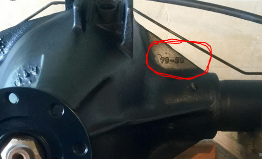
Definitely the fronts in ours are Dana 60s. Our rears depended on transmission and 3/4 ton or 1 ton. Automatic 3/4 tons got the Dana 70-2U. Standard transmission 3/4 tons and all 1 tons got the Dana 80. Do take this with a grain of salt as some things could have been replaced and sometimes things just don't follow the rules. It is Highly possible if you clean the webbing towards the drive shaft on the carrier casting, you will see the model number cast there. HTH Hag EDIT: Dana 60 and Dana 70 use the same rear cover! don't let that fool you. Some internal parts are the same (carrier bearing IIRC) but the pinion bearings are different and the ring and pinion are larger IIRC.
-
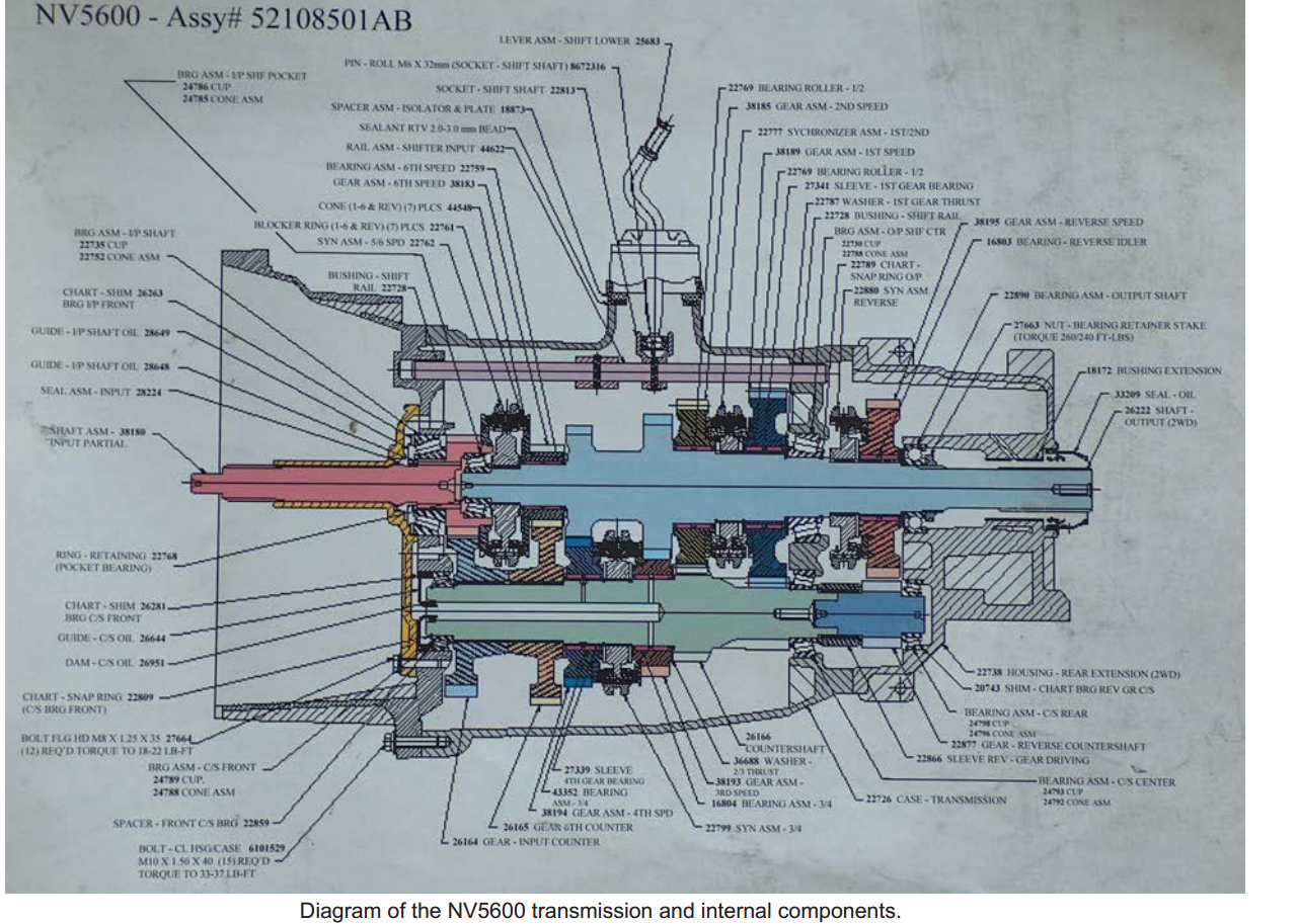
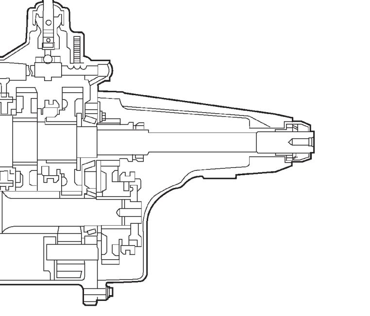
Ahhh I got ya. If this is a correct cross section, Unless you need to know the end play of the dark blue short shaft (reverse) in the lower right, you can get all you know with tail housing on. (it looks like you have to properly pre-set that reverse shaft before you assemble the tail housing on to begin with....) I also found a TDR write up of a rebuild (very limited) and attached it. Hag TDR64_RebuildingTheNV5600(1).pdf
-
It sounds like your vacuum pump may not be turning your power steering pump. (there is a drive coupling that connects the two.) Give these guys a call. They are in Murphy NC. (I was thinkin' it was closer to you, but it is not.) still a great fellow to talk to about these situations. https://www.fixinrams.com/ HTH GL Hag
-
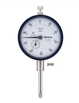
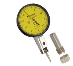
Stanley, I am not sure I can help much, never done a 5600. But any time I measure endplay (mainly crankshaft thrust) I use a dial probe or test indicator directly on the end of the shaft, on a magnetic base connected to the case (in my case the block). I then use a nice sized pry bar and push the shaft relative to the block in both directions. I set zero on one direction and directly read endplay. For counter shaft (if you cannot get to the end of the shaft ie trapped bearings.) I use a dial TEST indicator, and use the side of a gear. Here are a couple pictures of the difference but the Test indicator is very nice to help you reach into limited clearance areas, but still see movement. from the mitutoyo website probe type From mitutoyo website test type or "finger" type hope that helps! Hag
-
hmmm, I wonder if I remember an earlier discussion.....(the mind is a terrible thing to lose... if you see mine, let me know please...) I do remember trying to find what the ACTUAL installed diameter range of the bushing should be, and what the yoke ACTUAL dimensional tolerances are so I could calculate the actual bushing clearance.... but alas those are hard numbers to find. Do keep in mind, the bushing is a press fit. So if your clearance uninstalled is the same as what you have, it will be tighter when the new one is installed. It also may be worth a check that the tail shaft is not upside down. There is a drain hole that should be on the bottom, draining the area between the bushing and the seal. Hope you figure it out DF! Hag
-
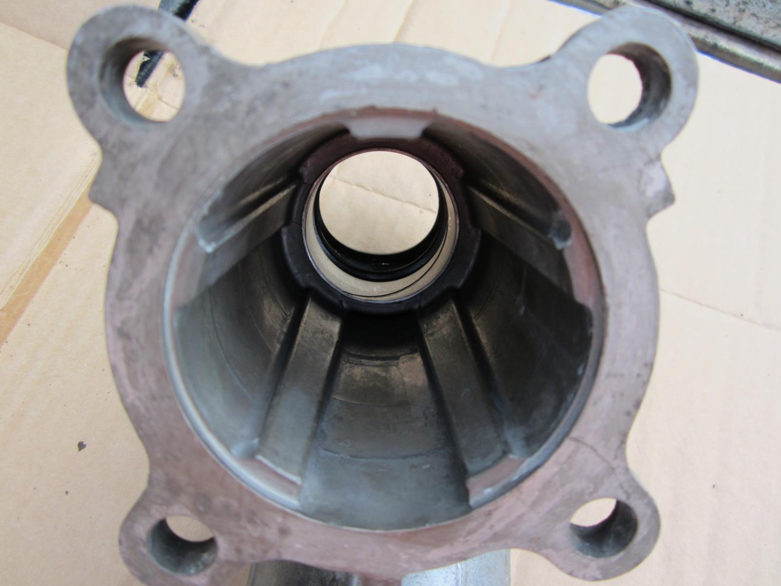
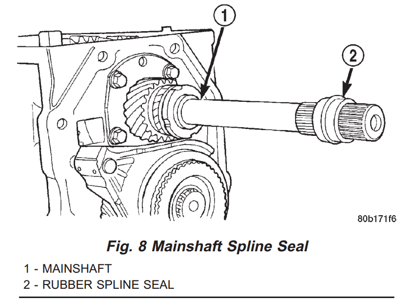
Greenlee, I would say it is the output bearing is beginning to fail, or the yoke is not round/correct size anymore. You may be able to correct both. The schematic seems to show that the rear support is pretty easily replaced. I am not seeing a bearing in the schematic from the FSM. It appears the 2wd rear housing comes off easily and you could look at the problem. The manual also notes a rubber spline seal. this would keep the fluid from creeping through the splines in the yoke. (possibly the 2wd tailshaft extension housing has a bushing ala the TC tailshaft? DF, The tailshaft on the 4wd has a bushing in it. As that bushing wears it will not control the yoke properly and the seal will be damaged. This is a picture I had when I needed to get a new tail shaft. (there were two different casting numbers but both worked ok) HTH Hag
-
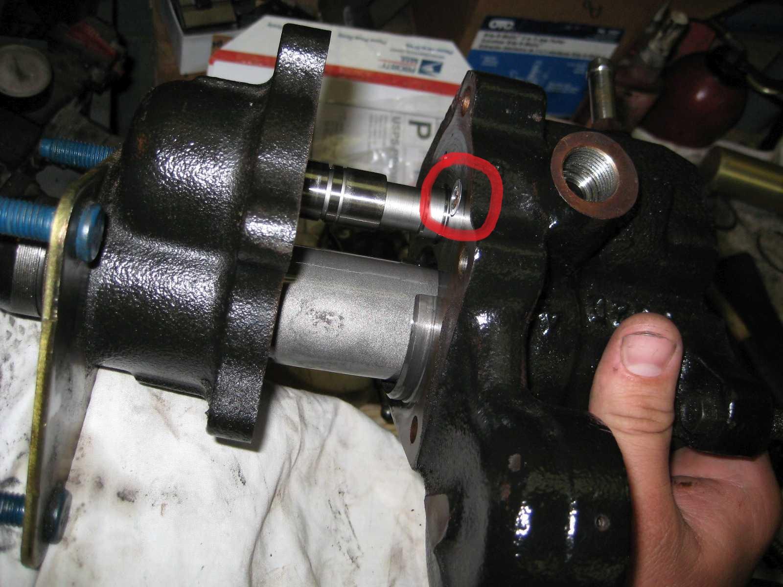
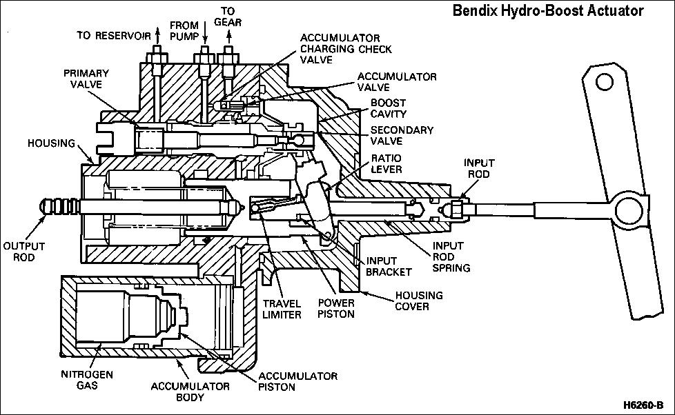
I am pretty sure that is the accumulator charging check valve. Here is a picture of where it is located. I have never had mine out so I don't know that part behind it. I am unsure of the direction it is installed. HTH Hag