

Leaderboard
-
- All areas
- Events
- Event Comments
- Files
- File Comments
- File Reviews
- Images
- Image Comments
- Image Reviews
- Albums
- Album Comments
- Album Reviews
- Blog Entries
- Blog Comments
- Cummins Articles
- Cummins Article Comments
- Cummins Article Reviews
- Vendors
- Vendor Comments
- Vendor Reviews
- Ads
- Ad Comments
- Ad Reviews
- Policies
- Policy Comments
- Topics
- Posts
-
-

Tractorman
Yearly Subscription76Points1,564Posts -

Sycostang67
Monthly Subscription23Points614Posts -
PilotHouse2500
Yearly Subscription20Points448Posts -
yohon
Yearly Subscription15Points102Posts


Popular Content
Showing content with the highest reputation since 03/18/2025 in all areas
-
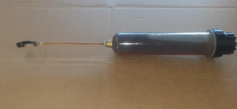
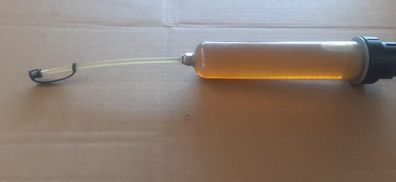
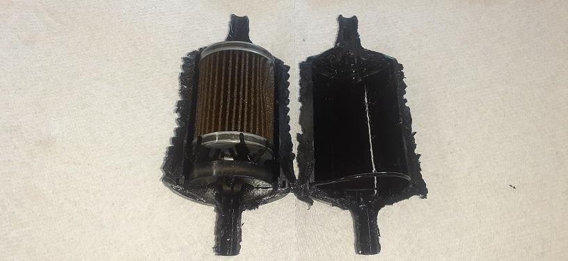
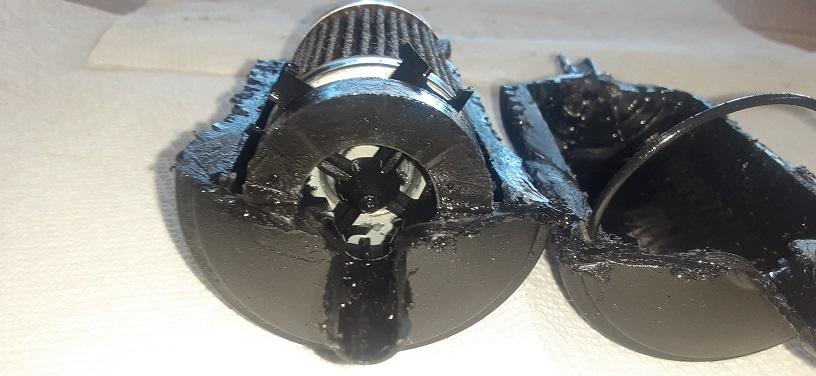
On September 6, 2016, I wrote the article "Adding inline power steering filter with system flush" and posted it in 24 valve 2ed generation/Axles, Suspension & Brakes. This is the follow up to that article. Update...7/25/2025 It has been 8years 9months and 44,888 miles since I installed the Magnefine filter and flushed the power steering system, so it was time to flush the power steering fluid and replace the filter again. I used an oil syringe fluid evacuator pump this time to remove and refill the fluid at the power steering pump. The picture below shows the first time the fluid was removed from the system It took 5 remove, refill, and run engine for 4secounds to get the fluid to this clear color, about 2qts. Here is the filter cut open. It looks like the filter could last 60,000+ miles before changing. There was just a fine film on the magnet.
 4 points
 -
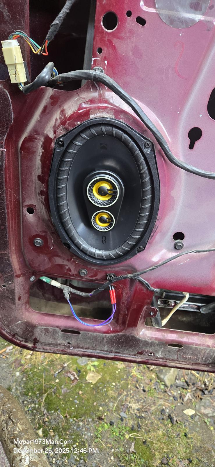
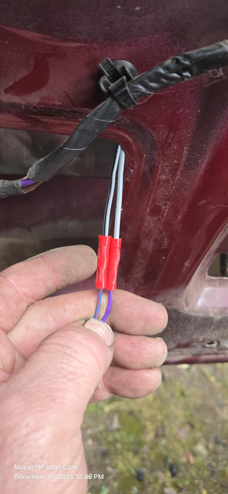
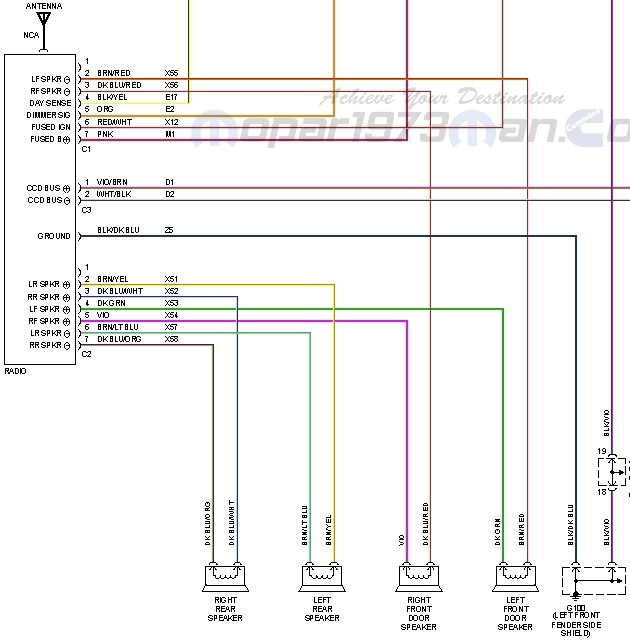
3 pointsYup after all the years and miles driven I've had a bad speaker on the passenger side. @Tweety Bird said, "Get this fixed! Time to get new speakers in Beast!" @Tweety Bird and I went to a stereo shop in Lewiston ID to look at speakers and prices. Great quality is really pricey say like $350 for a pair of speakers that really sound rich in frequency. Being budget mined I jumped over to Amazon and found. Kicker Dodge Ram Truck 1994-2011 Speaker Bundle - CS 6x9 coaxial Speakers, and CS 5.25" coaxial Speakers. Yeah Dodge and there strange wiring schemes. I'll list out the positive and negative wiring for each speaker. You can see I cut the factory OEM speaker plug off and wired in the new blade style terminals. Be aware of the polarity of each wire and speaker lug. In this set, the Kicker makes the ground with a black strip, and the positive lug is marked red. Left Front + Dark / Green Left Front - Brown / Red Right Front + Violet Right Front - Dark Blue / Red Left Rear + Brown / Yellow Left Rear - Brown / Light Blue Right Rear + Dark Blue / Orange Right Rear - Dark Blue / White
 3 points
 -
3 pointsElectric Vacuum Pump Conversion: I have deleted my OEM vacuum and power steering pump(s). Instead, I have modified it by replacing it with a midrange setup for steering assist; however, I still need vacuum in order to activate the HVAC controls and to activate my exhaust brake. Although the OEM factory pump never gave me any issues and supplied all the vacuum I needed to work, such as the HVAC and the exhaust brake, the OEM Power Steering did. I have replaced the OEM Power Steering Pump multiple times. In all cases, the pump would not maintain enough pressure and turning the wheels at a stop during idle was almost impossible. Compound that with the inevitable oil leak between both pumps, I figured there was a better system. So, this is where the "midrange" setup comes into play. The 24V ISB was used in multiple applications (not just Dodge). Even though they were not used in another pickup, they were used in midrange sized trucks like Freightliner FL60 &FL80, Ford 650 & 750, Kenworth 370, motor homes, bread trucks, etc, etc. It was the engine of its era. Trucks with vacuum controlled cruise should work also. This particular modification applies to my setup only; (the midrange setup for steering assist). My cruise is ECM controlled. I have the non CAD front axle, so my vacuum demand is limited. On SD applications, they use it to lock the front hubs and HVAC on their trucks. So I feel it should work on any of our vehicles. I used the same pump from the SuperDuty and 3rd Gen RAMS (same pump). I picked it up from Rock Auto along with a Mating Connector. I drilled 3 holes and mounted it on the fuse box cover, in an easy to service spot. For plumbing, it goes to a control manifold for the EB, and tees off into the OEM vacuum line on the firewall. I do not use a reservoir like FORD uses, but you could run one if you desire it. For power, it gets fused voltage from the PDC power stud, which is also the relay supply power (pin 30). The relay trigger is controlled by a fuse tap in one of the PDC fuses, that is hot only when the key is on, so it does not run all the time. The pump has an internal governor, so when it reaches its vacuum threshhold, it shuts off. If it is always running, you most likely have a leak that you need to repair first.3 points
-
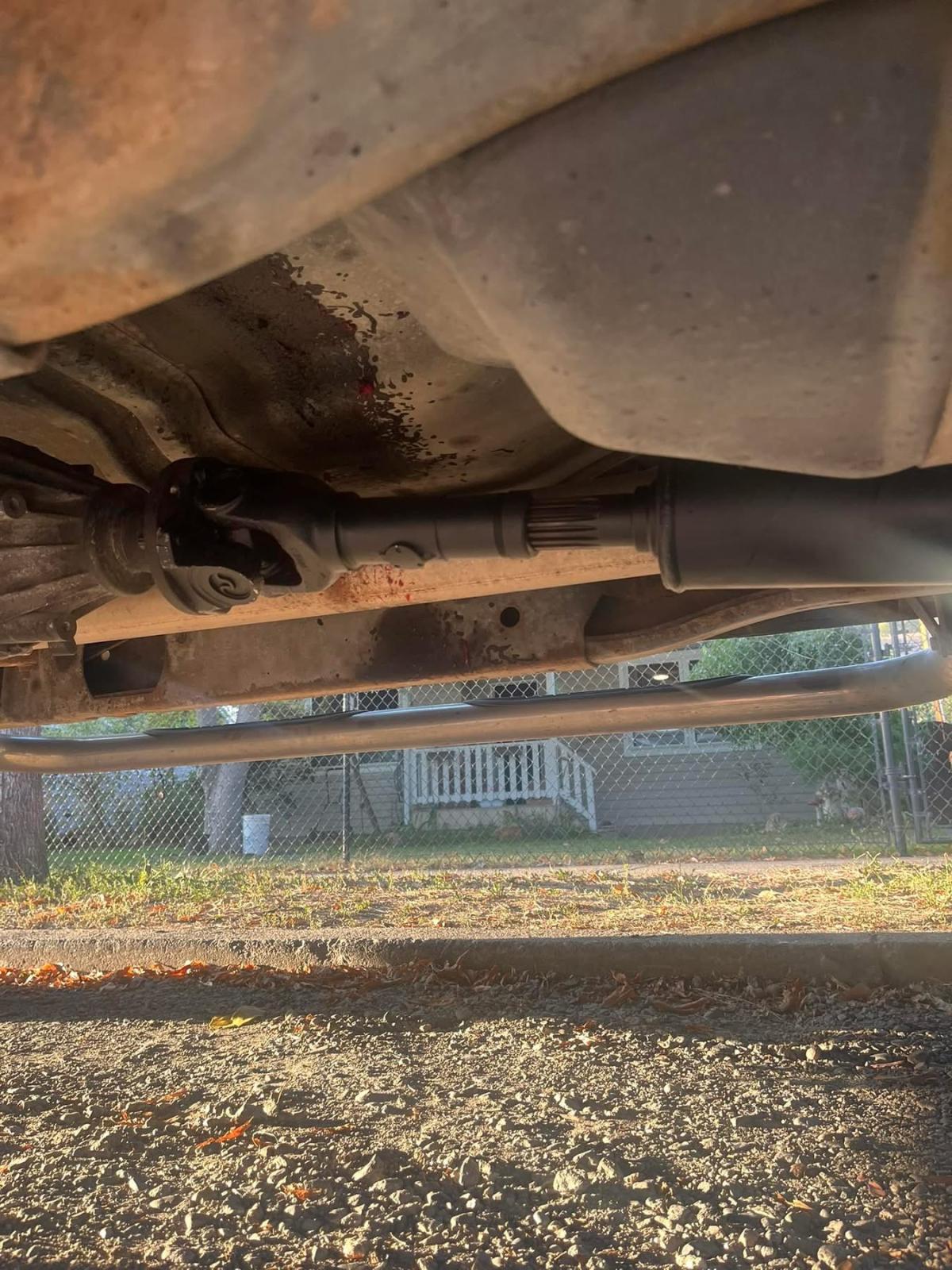
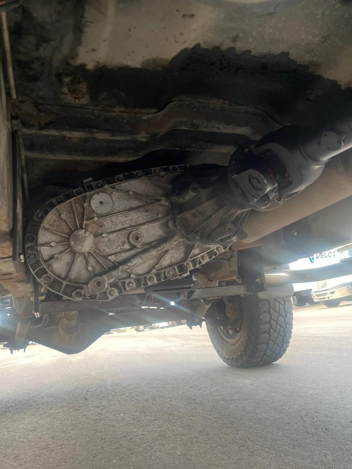
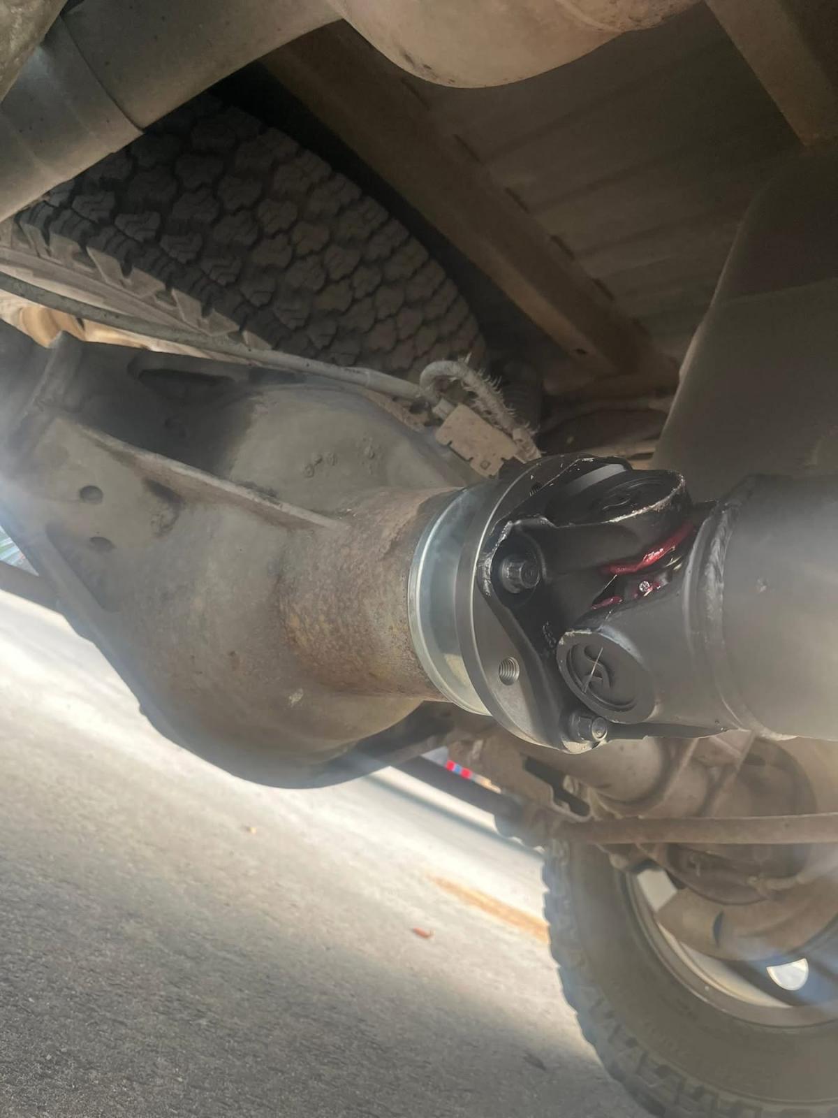
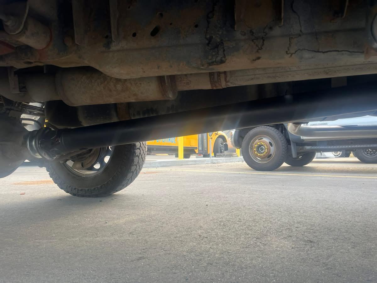
3 pointsI thought I’d share my recent drivetrain upgrade I put in my 01’ 3500 (SRW converted) 6 spd. On transfer case side of things swapping a NP271D in is pretty common for a 2nd gen. I wanted to take it one step farther. It took some trial & error finding what parts will work and what doesn’t. It’s pretty much a modified Ford design. I found a used 08’ NP271D and rebuilt/modified it. Eliminated the leaky Dodge slip yoke tail housing and utilized the rear fixed flange yoke setup from a 06’ NP273F. I bought the rebuild kit, some updated parts & specific seal installers from TorqueKing4x4. I also installed the Ford style companion flange on my Dana 80 along with a new washer, nut & seal. ***Snap-On # M3586 is the correct thin walled 1-7/8” socket if you ever need it.*** Initially had a 5” aluminum driveshaft but the Sonax slip yoke kit is quite expensive so I had a 4” steel one locally made and upsized it to 1480 greasable ujoints (OEM are 1410). T/case fits perfectly. There’s 1/8” of clearance at the frame and no contact at bottom of cab. The 2nd Gen linkage rod (11”) is a tad short so even set at max travel the shifter will be off just a touch. So I replaced it with the 3rd Gen 16” one and now it’s perfect. I don’t have the cad Dana 60 so the momentary ball switch from the old NP241D-HD just swaps over to make the 4wd light come on. I have the LRG trans crossmember so I didn’t have any interference with the front driveshaft. APPS delete ✅ Midrange power steering ✅ Electric vacuum pump ✅ Next project: Dynatrac high pinion 35 spline Dana 60 3.73 gears with an electric locker… Enjoy!
 3 points
 -
3 pointsMike if you lived closer I would kiss you. I had to remove the t-case boot to replace some wires and left it in neutral. 🤦♂️3 points
-
3 points
-
3 pointsWell the news isn’t good, after talking with the folks at GoECM they have confirmed the processor is bad in my ECM and is not repairable. Thankfully they are applying my repair cost towards the purchase of a new(reman) unit. I would assume this may be why the ACS repair didn’t work. I don’t know enough about these things to know if they would have been able to test this in depth. Their cost was much cheaper than GoECM so I’m not going to say anything negative about them. According to the info ACS sent me it sounds like they tested and repaired the parts I knew weren’t working. I’ll update again when I receive the new ECM and get it installed.3 points
-
3 pointsI hope they find what the problem is. Please let us know how it works out with this ECM repair shop so we can update the article "List of Verified and Reliable PCM/ECM Rebuilders" in the 24 Valve 2ed generation engine section.3 points
-
Here are some threads to peruse that may offer some insight. I have performed both mods about 1 year ago - well worth my time and expense. John2 points
-
I will have to take you up that. I thought I had a slight grasp on it before the accident but after with the TBI and my memory loss Im not making head way. Nothing like waking up to that smell...🤮 Possibly, tomorrow might be better. I got this late and were cooking dinner then showers etc and all the fun stuff before bed time. Ill make sure to plan it accordingly, can we do around 6pm tomorrow? My listed phone is fine. Thank you @Tweety Bird for the kind words!2 points
-
Hi Stanley! I am so sorry to hear of your circumstances! 😬 I am also so very sorry regarding the loss of your sweet baby girl!😭 I have had a lot of loss of loved ones, but I never had any children (1st husband passed away from Cardiac Arrest in 2006 so we had too much to deal with his congestive heart failure at age 26, then heart transplant, survived 6.5 years post transplant). I can only imagine what you and your wife had to go through with such a tender loss of an infant baby girl!❤️ I am glad you are still with us, despite all of your trials and near death. 😲 If everybody shared their life experiences, we would find that many people have suffered much tribulation, like ourselves. You have been through so much! We welcome you to post any of your diesel vehicle repairs or modifications, on the website...pics would be nice also! Keep on trucking🛻 along, as you have been! Pun intended!👍🙂 Oh...and, thank you very much for all your service in the Army (my dad served 23 years in the Army)🫶 And...Congratulations on your little baby boy!!🥰2 points
-
2 points
-
This is pretty accurate. One of my other cars is an Evo with a stroker engine that was built when I was still stationed in Japan. The builder told me that with the clearances, i need to run 20w50 oil, and that my minimum hot oil idle pressure is 15psi ( factory engine minimum oil press is like 5psi, gas engines are a wee bit different). The builder had used Motul engine oil, but that stuff was CRAZY expensive in Japan. I used LiquiMoly, hot idle pressure dropped by a few psi, still above the minimum, but it dropped. Then I tried ELF racing oil, and that could barely hold minimum psi, car ran noticably rougher. Enter Valvoline VR1. That stuff is AWESOME. I do not know what valvoline puts in there, but its amazing! super resilient against breaking down, holds hot oil pressure even better than Motul. And it is very reasonably priced. Mind you, this poor car gets hammered and abused every single time I drive it. It really brings out the pissed off teenager in me. Lesson here, all these oils were 20w50, and while in theory they should all perform somewhat similar, this couldn't be further from the truth! And now I have a case of VR1 on the shelf at all times. Also, I checked the AMSOil dex 3, and its cold pour point and cold flow performance are FAR superior, but it is synthetic of course. research will continue.2 points
-
Long posts are appreciated - especially when they are informative - like yours. I'm leaning toward your new low-stall converter triggering this issue. A stock converter has a stall speed of about 2,100 rpm, so it does not put much of a load on the engine when "drive" or "reverse" is selected. Your new converter probably has a stall speed of around 1,800 rpm, so shifting into gear will load the engine much heavier, especially in cold weather. I vaguely recall that there was an ECM update (referred to as "Anti-stall") around 1999 for these VP44 trucks. I think it was geared for the manual transmission trucks, but possibly the automatic trucks as well. Maybe @Mopar1973Man will chime in on this topic. Have you tried taking the Edge EZ completely out of the circuit? John2 points
-
2 pointsGive details of your bucket test. Have you ran the engine while drawing fuel from the bucket with a separate power source to the lift pump? I'm having a hard time with believing it to be a VP44 overflow valve problem. Did the FASS representative explain with detail on exactly how an VP44 overflow valve problem would adversely affect lift pump pressure? Also, if there is a restriction in the fuel supply anywhere in the lift pump circuit (especially the suction side), then unpredictable fuel pressure could be expected. What it the GPH rating on your lift pump? John2 points
-
2 points@Tractorman Those o-rings are square cut and you would need to order from Cummins for replacement. Might be a good idea.2 points
-
2 pointsOn my truck the tee at the back of the head started to leak fuel about 15,000 miles ago (at 390,000 miles). At the time I had the transmission out while doing a clutch job and I noticed the leak. The connections were loose, so I just tightened the them from below. They have never leaked since. A leaking tee fitting (even if it's only leaking air) can cause long cranking times, but it will not affect fuel pressure after the engine is running - so, not likely to be your problem. I haven't tried accessing the tee fitting from the top of the engine. I would probably remove the valve cover and use a mirror to inspect the connections and then blindly reach around the back of the head to tighten them. John2 points
-
2 pointsSame speakers I put in my truck three years ago. They sound all right. My son says I should put a small base thumper under the seat so that I can "feel the music". Just what I need to go deaf faster.2 points
-
Timbo is a repackaged Williams Control. WC 131973/133284 is what they actually are.2 points
-
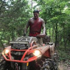
Funny part of this marriage. I had to have the cancer and the ostomy bag to meet Suzanna, my wife. If I'd been a healthy person, I'd never have met her. She enjoys the thought that I dealt with my depression with makeup artistry and cosplay. This helped me deal with the health crisis (bladder cancer and chemo treatments) I was dealing with at the time. I started making up artistry back in 2022 as a fun thing for the weekend. Now it's part of my daily dress code. Suzanna has enjoyed the interactions I get everywhere I go, hence why the photo above shows us both enjoying the makeup work, and will continue to grow together with our own art. The makeup artistry is what captured her eye that day, and why we are together. Being we both went through our own hell, we plan on holding the celebration next year in late spring or early summer. Hopefully, by July 25th 2026, we can be on top of Heaven's Gate, where you have to drive through Seven Devils Mountain to reach this mountain top.2 points
-
2 pointsBut..., before you replace any parts - make sure the transfer case shifter is NOT in neutral. Just sayin'... John2 points
-
2 pointsHe removed both units and installed a gear driven power steering pump directly onto the accessory drive gearbox. He also installed a remote power steering pump reservoir. Here is a link to his original post regarding the conversion. You will need to scroll through the whole post as he talks of other conversions, as well. I made the same conversion myself - very happy with the results. It's nice having an accessible see-through reservoir. The direct mount power steering pump definitely out performs any of my previous pumps, including the OEM pump. John2 points
-
2 pointsI bought my parts from a combination of allstate gear and torque king I believe. I had to replace the input shaft, main shaft and counter shaft. Mine was pretty trashed. I also replaced the tail housing, OEM was an aluminum peice, I replaced it with a cast iron piece from torque king.2 points
-
2 pointsGlade to hear it. This means that GoECM fixed what ACS could not. A big plus for GoECM.2 points
-
2 pointsPraise the 8lb 3oz. baby Jesus my truck lives!!! I reassembled everything, hooked the batteries up and did a TPS calibration and it fired right up like it was running yesterday. Not to proud to admit I shed a tear or two of joy. 🥳2 points
-
2 pointsas always, I get freaked out if my truck is "down" and opted for the fastest (most reliable) fix. This is why I try to be proactive about maintenance instead of reactive.2 points
-
2 pointsAfter some thinking and talking to the wife, I’ve decided to send the ecm to someone else. I think the problem with ACS may be that their repair is based solely on the information I give them. The shop that fixed my turbos recommended a place they use out of Texas. I called them today and they test and check the entire unit. Just found out today my daughter can’t take drivers ed for a few more months so I’m gonna use the money we saved for that to get it done.2 points
-
2 pointsSadly I have nothing to "work" it with... it is back to daily driver status... I may hook onto the trailer and go pickup some firewood but even that isn't "working" it like I KNOW the truck likes. :) and the NOT WET status inside and down stream from the turbo is what most perplexed me... I was expecting "wet" as well.2 points
-
2 points:) only 300 miles so not really put it to a test yet.... but I haven't noticed any more peppiness. But you have to remember, my turbo was creating boost... just sending oil along with it.... so I am seeing the same boost levels.... I don't expect much to change minus not consuming oil.2 points
-
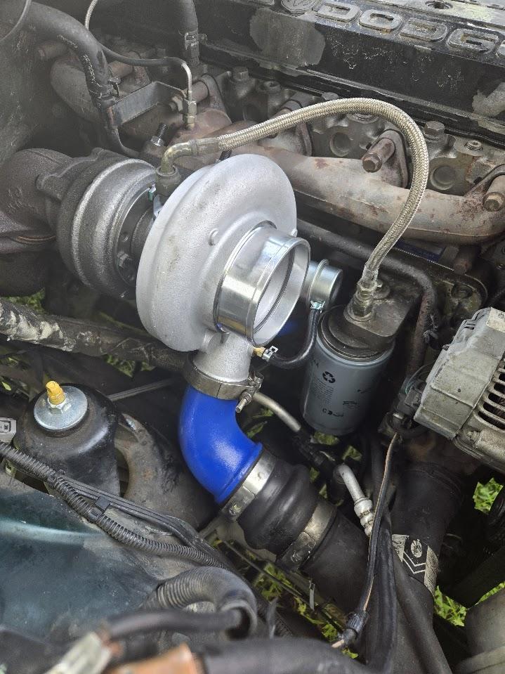
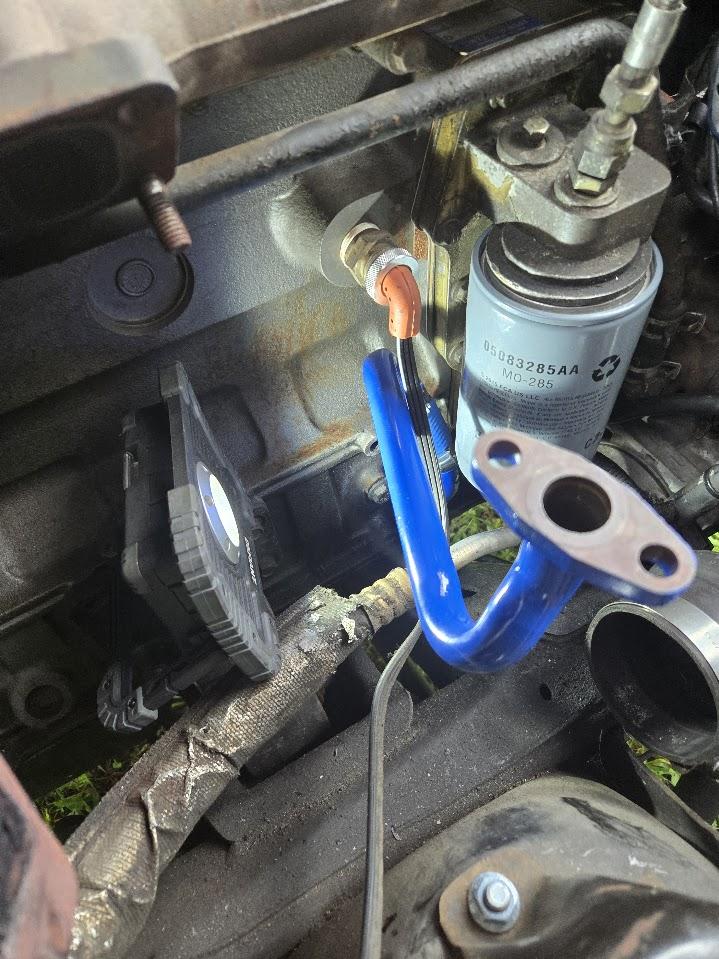
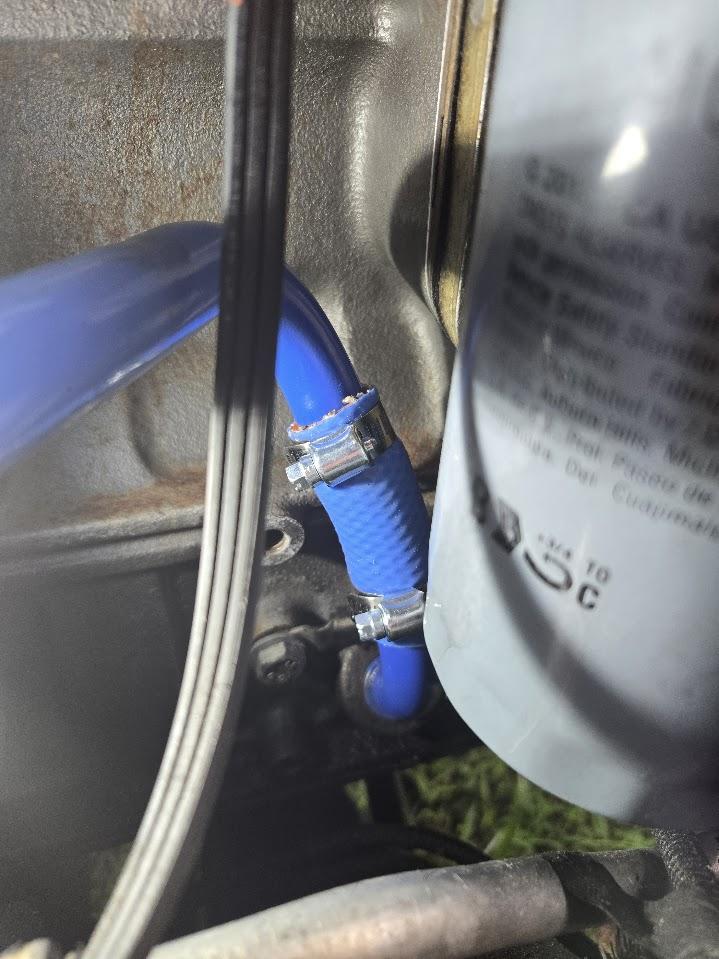
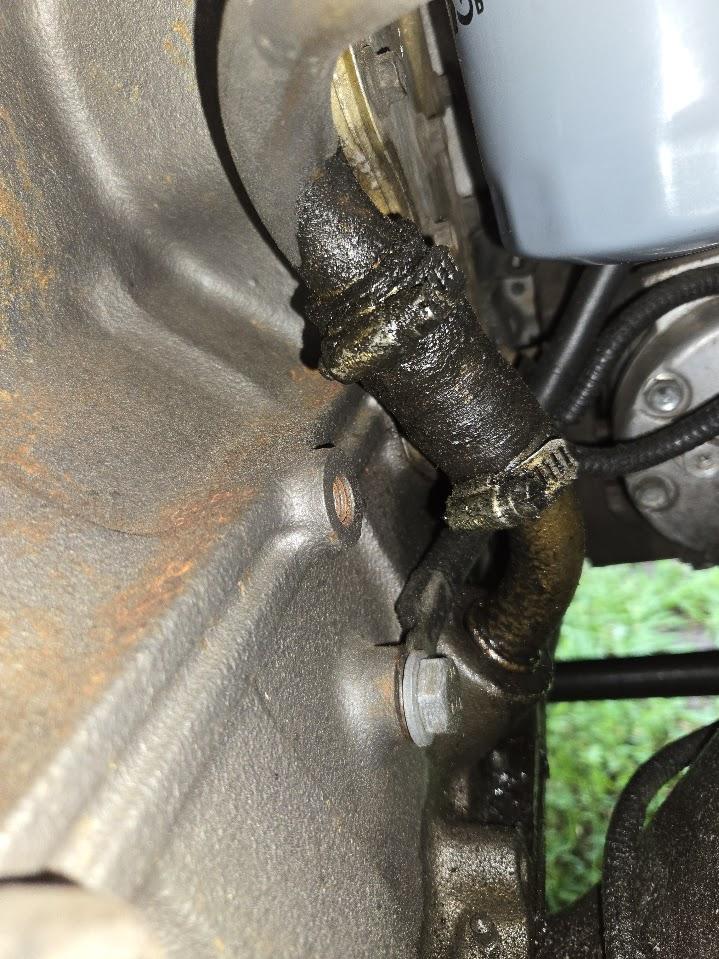
2 pointsSO... new turbo installed, apparently (only a 100 miles in) I no longer am losing oil. A few things to note... NO ONE knows what the "w" is for on the HX35w, I"m calling it "W" for WING... because the HX35 has a bracket for the waste gate which won't work on our trucks... the true "W" does. After I ordered my Rotomaster Reman Stock Turbo 99-02 I did find some actual "W" turbos for less... but considering I had to send mine back for a core $560 was not bad...just knowing it was all American... $250 and not sending my core in would have been nice, I could have rebuilt it myself and had a backup for when the Chinesium turbo failed.... I did paint some items to match. Here are the photos. One of which was the OLD oil drain into the crank case... I THOUGHT the wastegate tubing was going to come in blue... so I'll replace it later. IT BLEW BLACK smoke the first 10 miles, I am pretty sure that was just getting rid of the soot that had built up in the tail pipe.. because after it ran clean.
 2 points
 -
2 points
-
2 pointsObserving soot at the end of the tailpipe is normal for this era of truck, especially if you have larger than stock injectors. Disconnect the compressor discharge plumbing from the turbo and inspect for an oily mess. Then, disconnect the exhaust band on the exhaust side and inspect for the same. It is possible. The hone pattern intentionally put into the cylinder walls is used as a mild abrasive to condition the outer wear surface of the piston rings for the first 1,000 miles or so of driving. During this period of time, the best mating of the rings to the cylinder wall will occur, resulting in the least oil consumption and least engine blow-by. Using a slippery synthetic oil during break-in reduces the effectiveness of the abrasive characteristics of honing the cylinder walls - it will have a more likely effect of polishing the piston rings and the cylinder walls, resulting in more oil consumption and more engine blow-by. Try performing the oil cap rattle test for the poor man's method of checking engine blow-by. John2 points
-
2 pointsJust remember just one wire pinched in behind part, bolt, or bracket could do it. I had one where the PCM burned up because one wire was rubbing on the trans dipstick tube and fried the voltage regulator.2 points
-
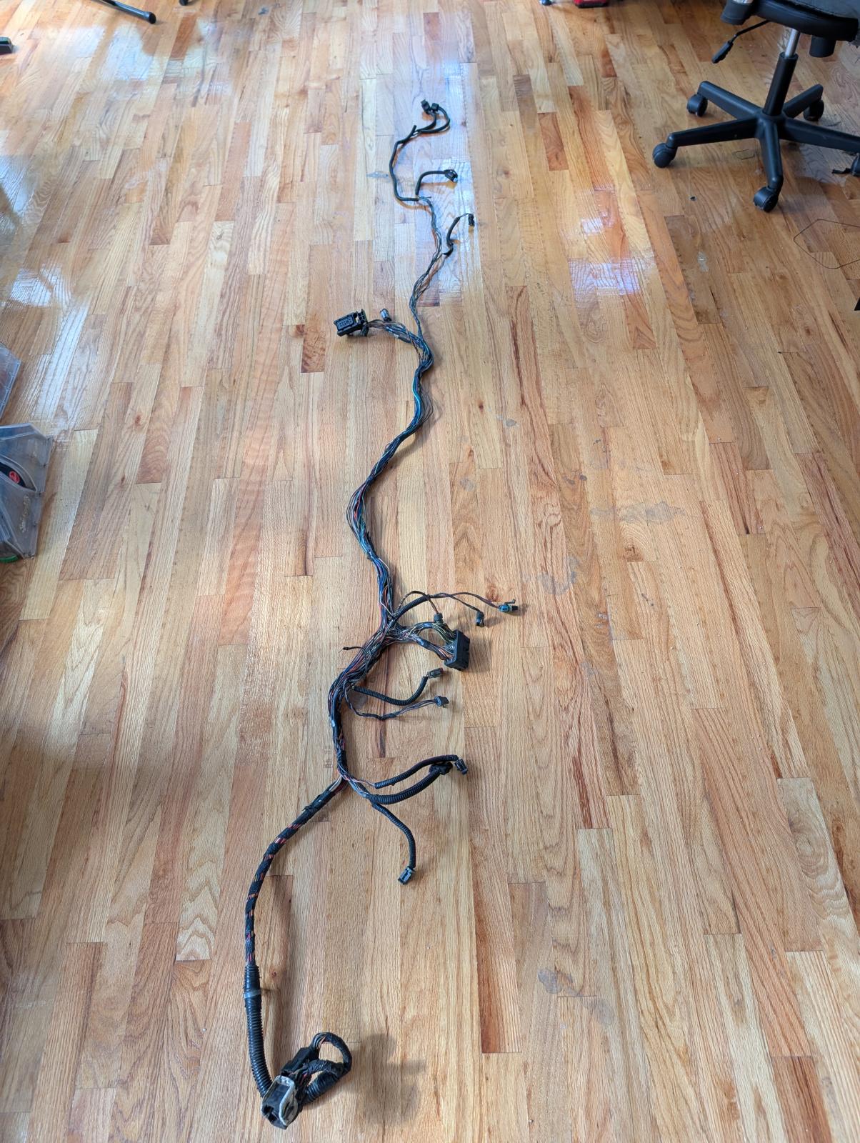
2 pointsThey listed a ton of possible causes for failure to check. Basically every sensor on the truck, damage to the harness, TSB’s, faulty grounds, etc. The truck ran perfectly and has for the last ten years when I pulled into the garage so I had no clue what to even look at. I did check some of the harness and found one tiny hole in a wire possibly from a probe, it wasn’t close to touching anything but I wrapped it up anyway. If I have time this weekend I plan to go through the whole thing and check all the grounds and fuses.2 points
-
2 pointsI ordered a front drive shaft from Torque King today. The sell strap and bolt kits for this application. https://torqueking.com/product/40709/qu40709-universal-joint-strap-and-bolt-kit-for-spicer-1350-or-1410-yokes/?searchid=1393311&search_query=driveshaft+strap+and+bolt+kit2 points
-
2 pointsThe only thing I can suggest is contacting https://idahodrivetrain.com/ . You should be able to get information from them,2 points
-
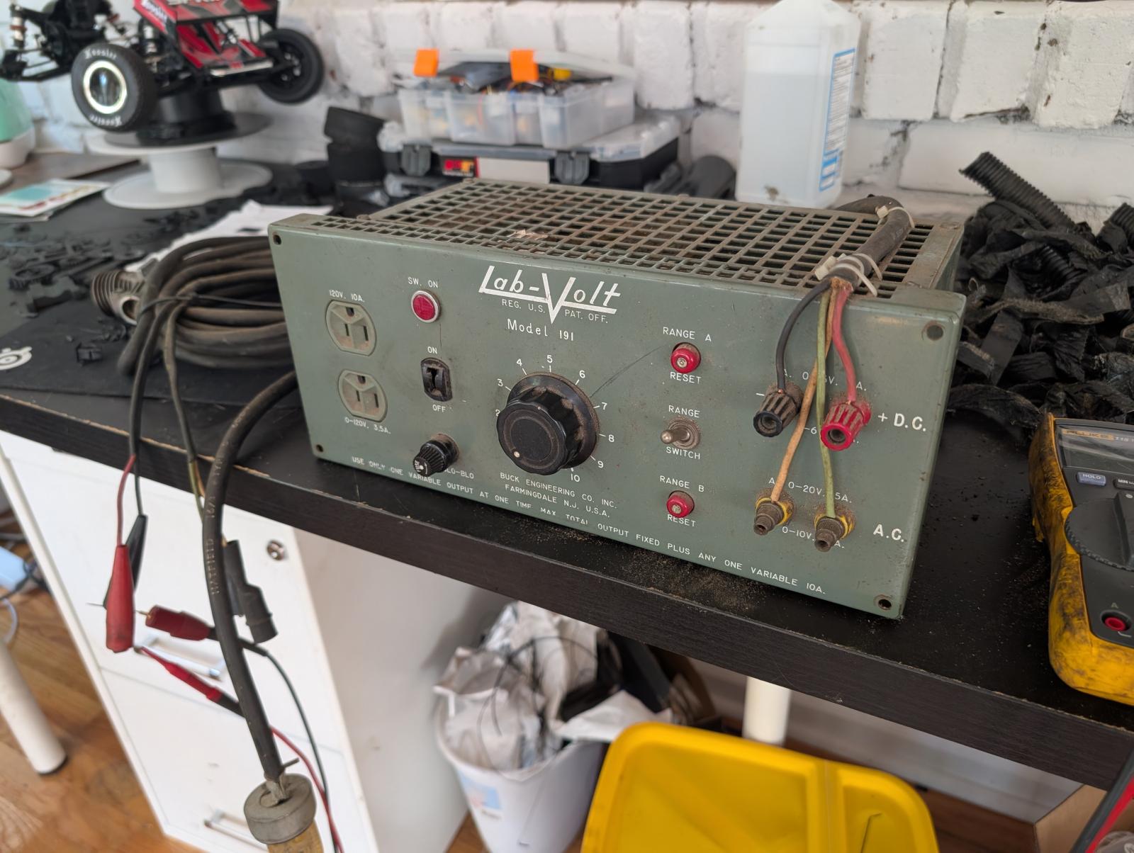
So far I have found nothing! It's not difficult, just time consuming. I have this old power supply that I'm using to help load test the wires! Good to know! Im a cheap *** and prefer to struggle my way through this LOL.
 2 points
 -
I appreciate the phone call as well. Good to chat with someone that actually knows what they're talking about! I hope to update this next week with a solution! This has been an ongoing thing for years now!2 points
-
2 pointsLooking back on the thread, Mike mentioned this a few days ago “Remember Bosch stock injectors are NOT made as a set. You could have low end of 293 bar you the high end of 327 bar. This can affect idle performance. Ihigh suggest AGAINST using stock injectors. Buy+50 HP from any good injector shop and they are balanced as a set within 2% of flow rate” I still think it’s very likely both sets of your injectors have been mismatched. I learned this the hard way over the past year or so. Had your same stall issue after I ordered and installed a matched set from the same outfit that did Mikes injectors. Pulled them out, had 2 shops pop test them and they ranged from 290 to 330 bar (both shops showed same numbers on each injector). Pulled them back out, send them back and told them specifically what I wanted (310 bar-I believe they set them up at like 308 normally) they sent them back and I had them independently tested again and they were still off-not as much but by then I was mad. Keep in mind this was a “premium” set, not their normal budget injectors. I tossed those and went with the Mach 1 from Flux bc the owners are still directly involved with building their injectors and they’re perfect. For whatever reason my 2000 model is very sensitive to matched/balanced injectors and it sounds like yours is too. This shows my truck stalling after shifted intro reverse. On a slight hill, if the initial fuel input didn’t create enough force to back it up it would just drop and stall. The pics below show the idle RPMS from 2 different tuners. Roughly 750.IMG_6135.mov IMG_6162.mov

 2 points
 -
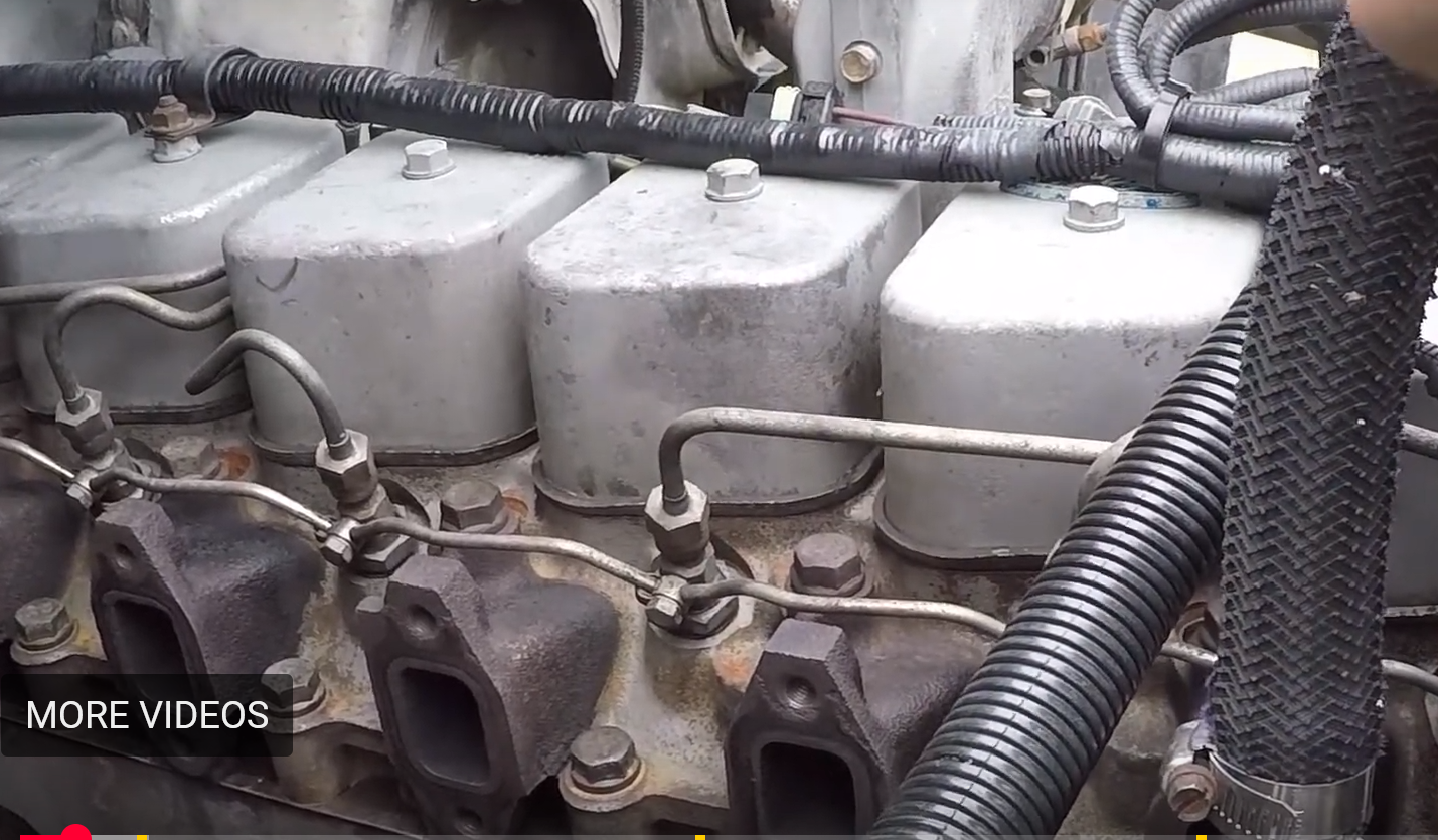
This photo is of a typical 12 valve engine. No crossover tubes. Fuel line are connected directly to the injectors, so injectors can be shimmed. John
 2 points
 -
2 pointsHi everybody, it s ok. The truck works now..... intéressant is no cut off.... The culprits: rebuilt injectors 75hp more, and tps ( I don t understand why it worked before... electronic 😁😁, like the vp44 😓😓). Thank you very much for your great help ! ! If one Day you go at Monaco send me a mail , it s with great pleasure !2 points
-
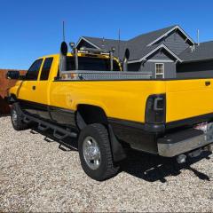
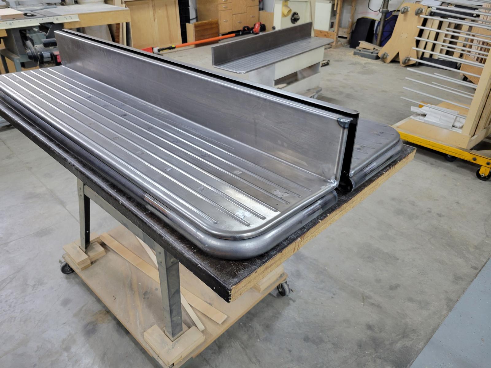
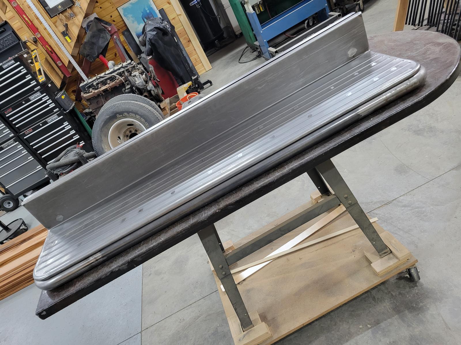
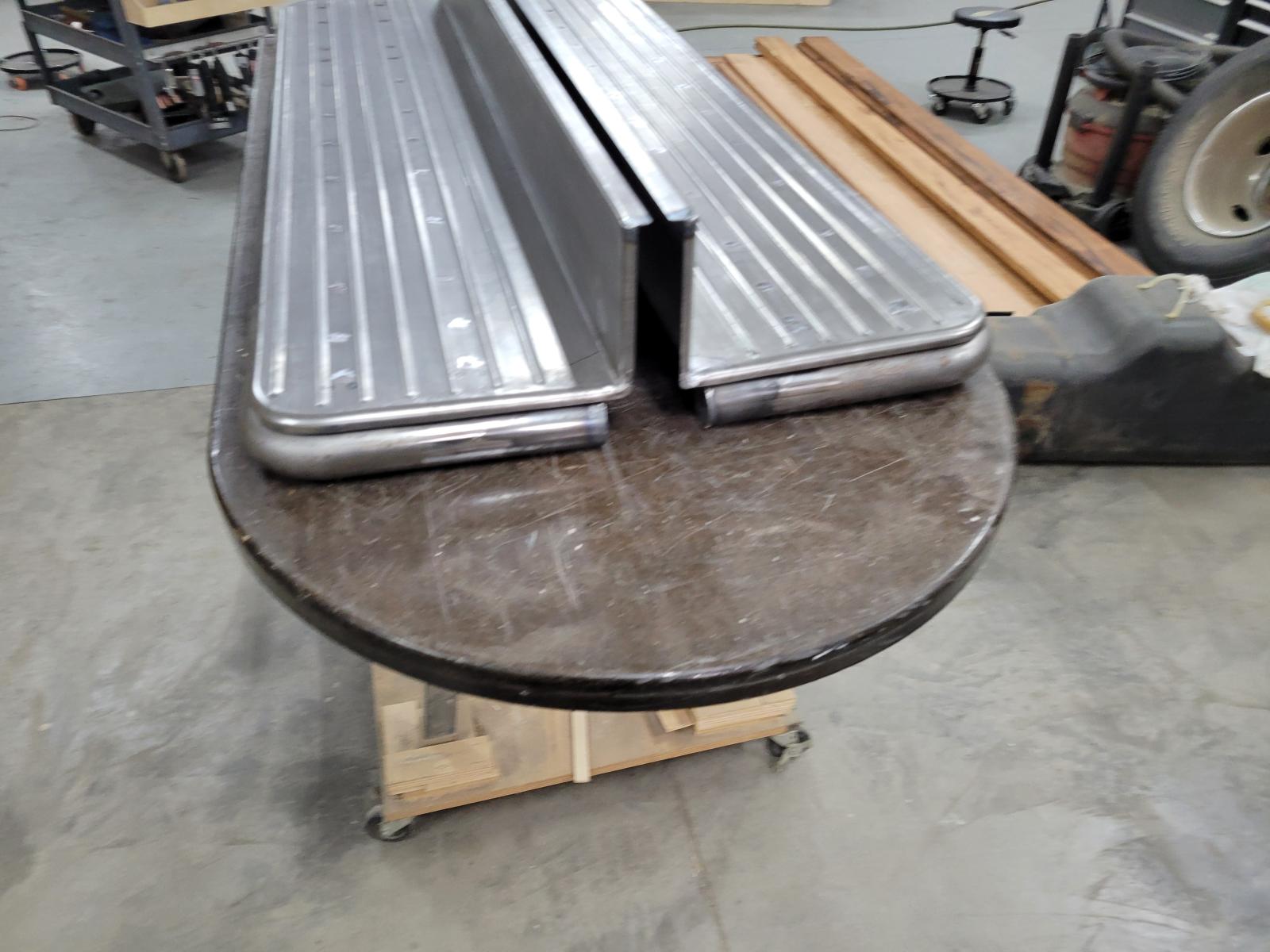
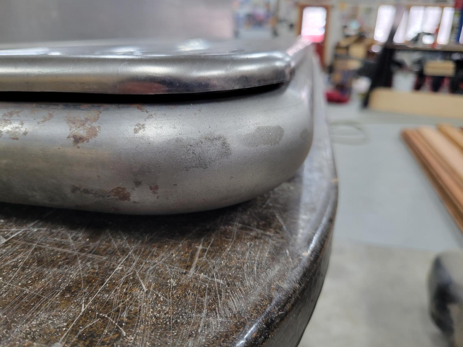
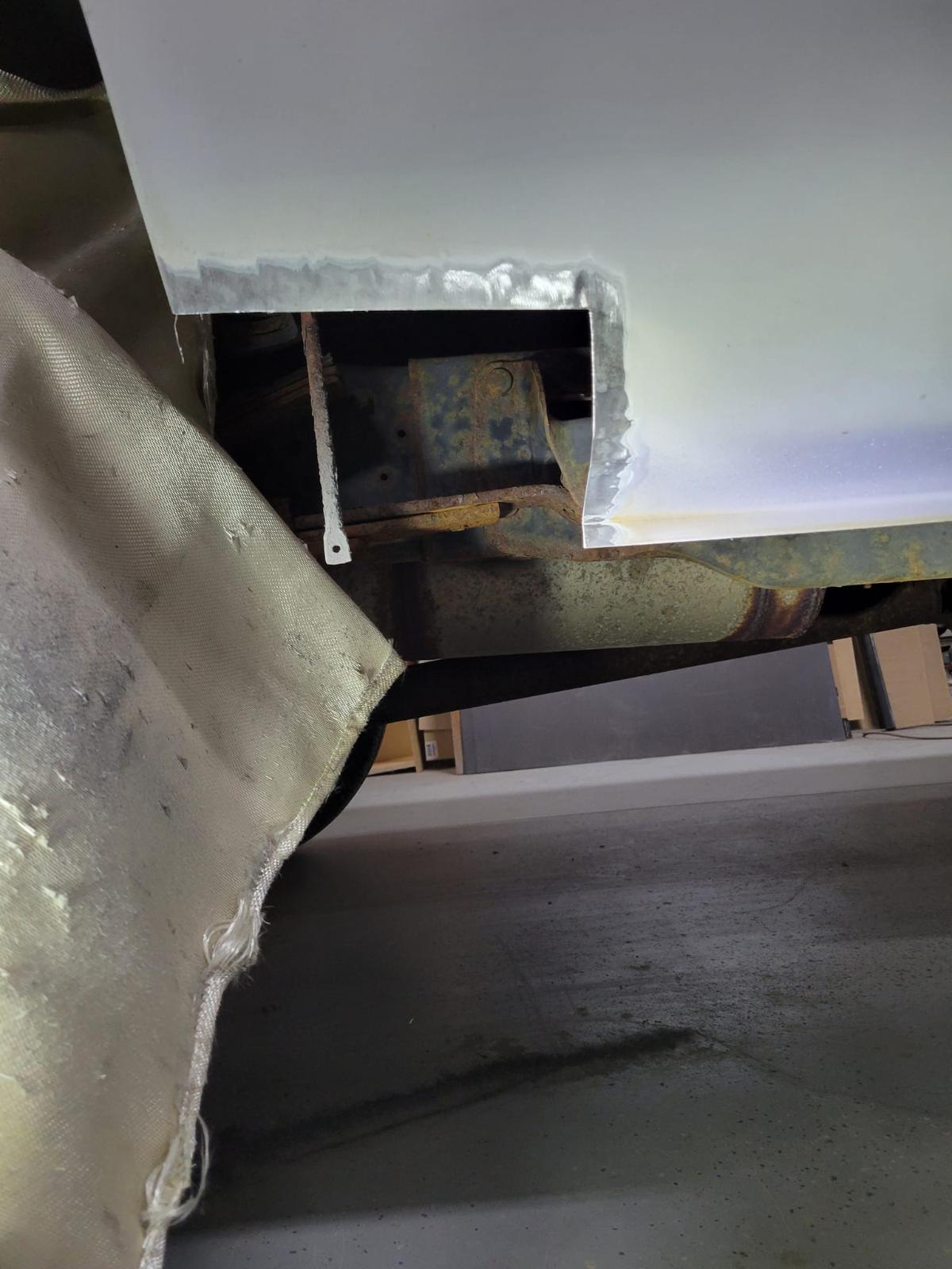
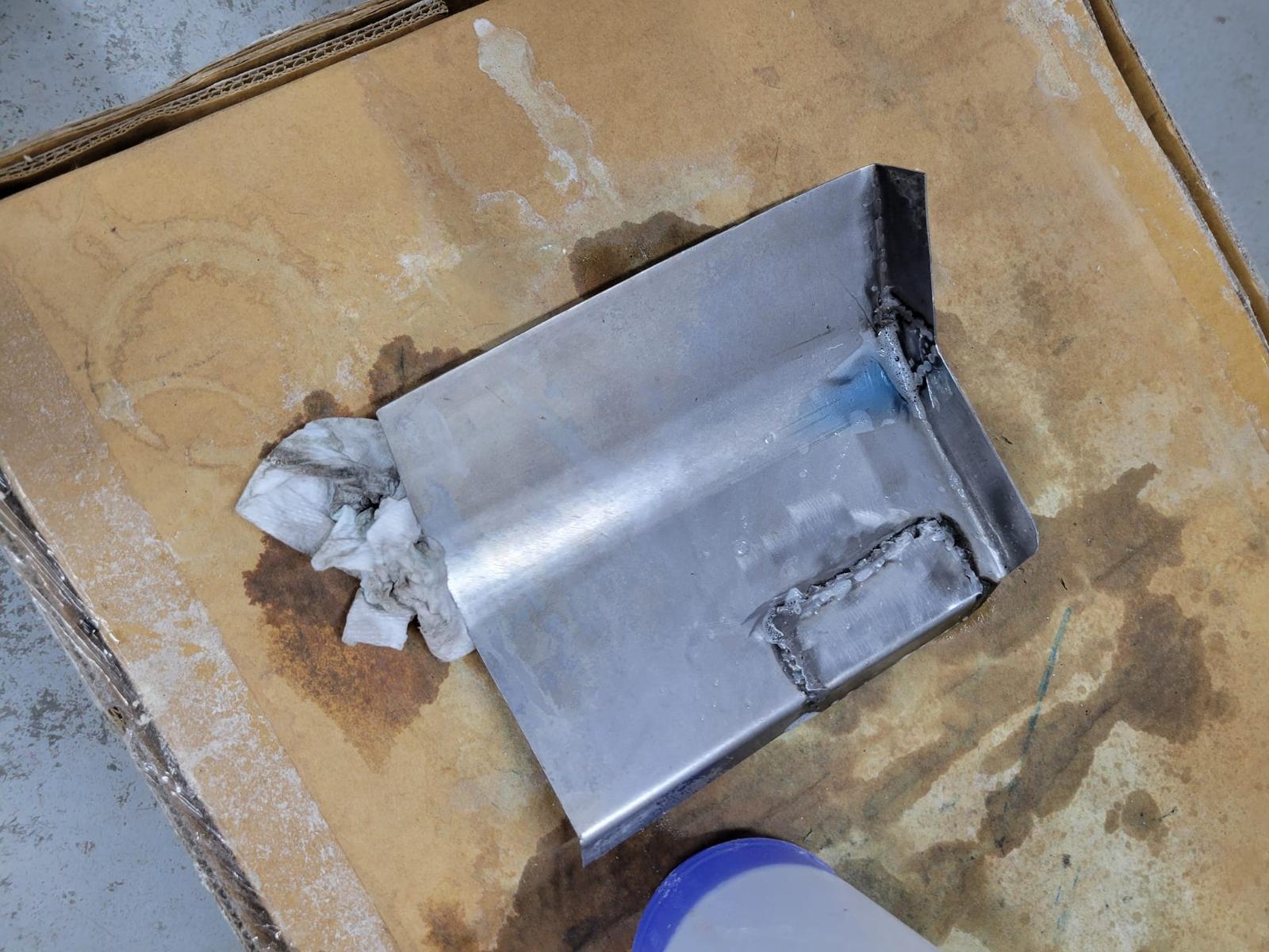
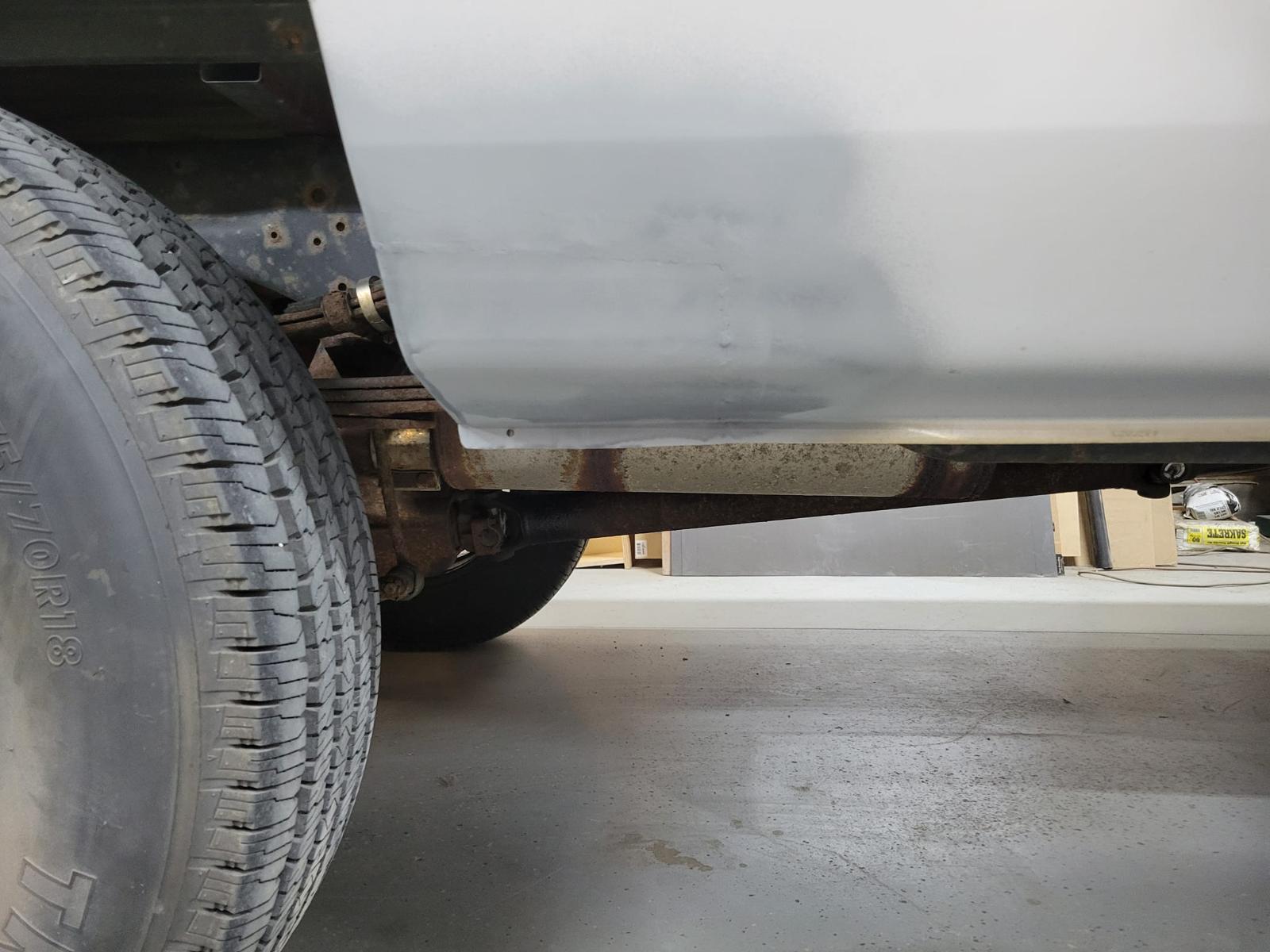
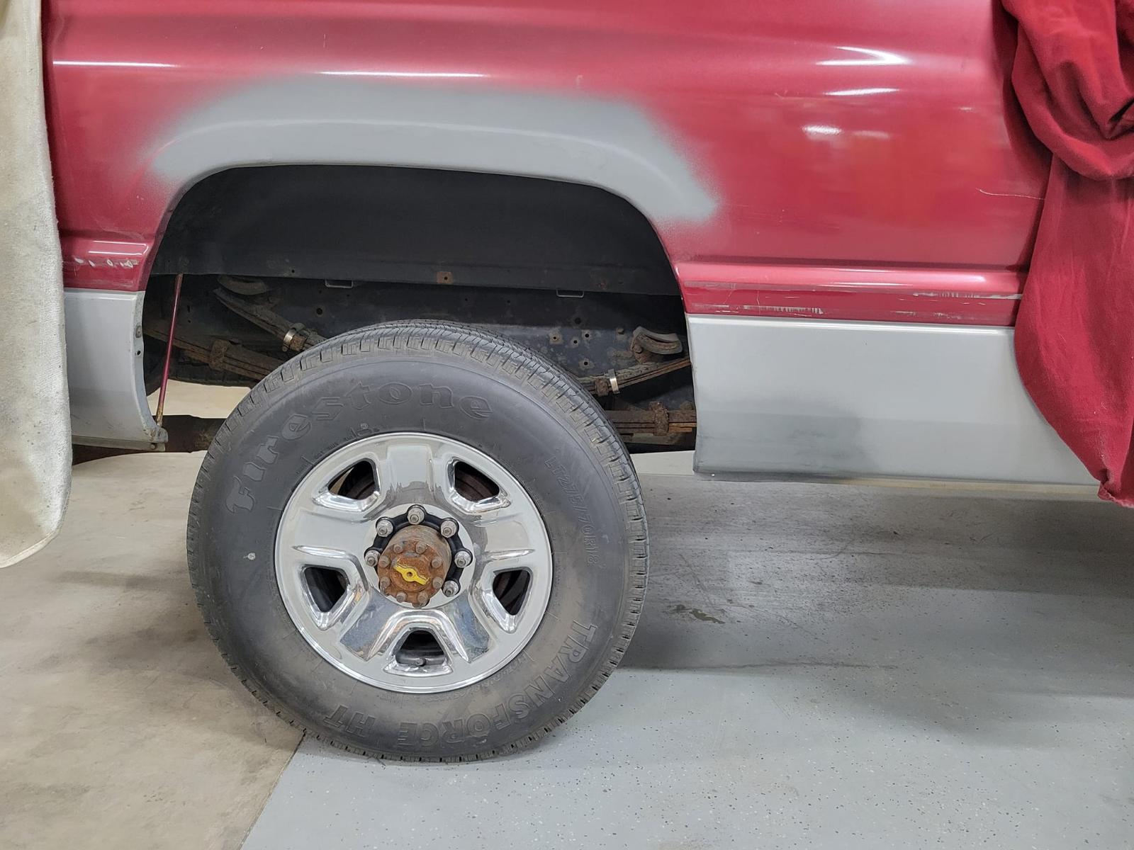
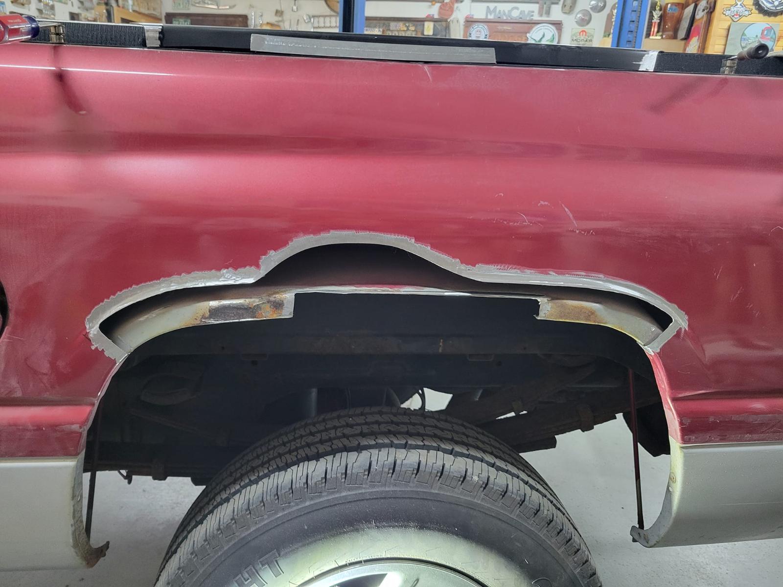
2 pointsRunning boards ready for dry fit. I know I have notch something for the cab mounts.
 2 points
 -
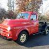
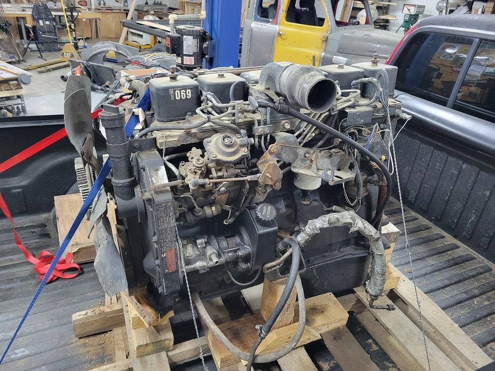
2 pointsMy buddy traded me a first gen 6bt to do some body work for him on his truck. So several patch panels later I got a "free" engine.


 2 points
 -
2 points
-
After 18 years of interesting CTD enthusiasts and transmission specialty outlets all contributing their method, or fix, to the well known TC lock unlock syndrome, I can no longer remain silent. Extensive review of many posts regarding TC lock unlock, the rerouting methodes, the add on filters for APPS and last, but not least,...the "tin-foil hat" brigade. I do realize that each individual or company that contributed to the vast amount of information on the web had good intentions and I must acknowledge that some of the procedures caused me to closely examine what these people were trying to do. I believe it is well known that even a blind mouse occasionally finds a morsel of cheese. Again, as it is well known @Mopar1973Man was the only entity who positively identified the instigating source of this key issue. My entry today is not about alternators...it is about what Daimler/Chrysler did in regard to production of these Cummins powered platforms and the complete disregard of common sense Electronic Engineering. Please note, this applies to automatic and manual transmissions as each platform is plagued in the same manor with different quirks. This Blk/Tan #8 gage wire is quite critical in the scheme of things. It is contained within a 1" plastic conduit passing along the front of the engine. It contains water temp sensor leads, air conditioning leads, alternator/PCM leads and the #6 gage alternator charge line to the PDC. This #8 gage Blk/Tan passes over the top/backend of the alternator and is "eventually" connected to the Auxiliary Battery (passenger side) negative terminal. This snapshot of the Factory Service manual documents "four critical ground leads" that are "spliced" in an unconventional method. This photo depicts the three #18 gage wires and the single #14 gage wire entering the shrink-tubing where the "crush-splice" occurs. This bundle exits the large plastic conduit below the VP44 This again is a most disturbing depiction of the Daimler/Chrysler method of splicing critical ground leads and then routing this across the top of the alternator and "eventually" bringing this to ground reference. This photo depicts where this #8 gage Blk/Tan first connects on the way to "eventual" ground...yes this is the Auxiliary Battery tray connector. Please note: it is spliced again and joins the PCM circuit board grounds...which are critical in their own nature...and "eventually" terminate at the negative post of the Auxiliary Battery's negative terminal. This photo is very interesting, it is the Factory Service manual and the assembly line documentation follows this as a road map in the matrix during production. Please NOTE the title "NAME" to each battery...I looked at this for a considerable amount of time before I realized the assembly line coordinators tried to work with the documentation from the Engineering Staff to "make it as it looks"...Could this single oversight be the reason of a four foot ten inch critical ground wire combination traveling the distance to "EVENTUALLY" terminate at ground? From a basic engineering standpoint regarding ground...you "NEVER CHOOSE THE PATH OF EVENTUAL GROUND" !!! It is to be the shortest and most concise connection in reference to ground...this is biblical in ALL ELECTRONICS...including pickup trucks. ! Here is the Factory Service manual documenting the PCM circuit board reference ground starting as a pair of #14 gage wires being spliced into a #10 gage bundle and arriving at the Auxiliary Battery through another connector that joins a #8 gage wire that is "splice-joined" under plastic conduit in a Y configuration joining the rouge #8 gage "after passing over the alternator" traversing the entire engine compartment from the driver side of the vehicle. Seriously I have been drinking excessively, most recently, due to the nature of this blatant discovery. This is the hidden Y splice at the Auxiliary Battery where the "mess" EVENTUALLY terminates for ground reference. This photo shows the correct "HOLE" of where to apply ground for the VP44, ECM and the PDC...note the logical location It took a little research to find the size and proper thread-pitch. Metric M5 with a 5/16" hex head is perfect This is where you apply a fresh "quality" #6 gage ground and terminate this at the Main Battery negative post on the drivers side for absolute ground reference for the VP44 and ECM This is a very short and concise reference to ground. This is the corrected procedure for a rather critical ground. The two largest wires originally contained within the 1 inch conduit are no longer present and located well away from the alternator. My alternator B+ "charge" line is now a #4 gage line directly connected to the Auxiliary Battery and when my new battery terminals arrive and they are secured, I'll provide photos of a completed Master Power Supply System within this engine bay. With these corrections, I would hypothesize that a poor ripple specification on a given alternator would be overcome by the immense capacitance of the parallel batteries and would become less prone to causing the dreaded TC lock/unlock for automatics and cruise-control abnormalities for the manual transmission platforms. The #8 gage Blk/Tan passing over the alternator as an "EVENTUAL" ground is gone...the PCM, ECM, VP44 and the PDC are now grounded in accordance of standard Electronic Engineering practices. Respectfully W-T2 points
-
2 pointsThe factory heat exchanger not only cools transmission fluid, but all so heats the fluid to operating temperature in cold weather. With the average winter low temperature of 9°F in your area it would be prudent to retain the heat exchanger for winter drivability.2 points
-
1 pointThen 2 things. Quadzilla only programs a running truck. There is the ability to see live data that's about it. OBDII code reader like OBDLink MX would be a good option.1 point
-
1 pointBoth @Tweety Bird and I gotta have a break from all this. I had to deal with rusted slide pins on the calipers front and rear axle. We managed to find enough of my tools to at least do a simple repair. Suzanna has been busy packing the RV so we can go take a break camping locally. I'm kind of amazed. Got the front brakes done with slide pins. Both side you had to beat the pins out of the boots. The last time I did brakes at 350k miles till now with 497k miles and rolling. Finished this project. Sadly I found my MPG loss. Driver side rear was stuck on the side pins and ate those pads up about 1/4 of a inch left.1 point
-
Armature shaft binding when cold. See if tapping on the housing frees it up.1 point
-
Having replaced the control arms, I definitely suggest buying the whole arm. Also, go ahead and get the bolts if you can't have your truck down. Mine were rusted into the bushing sleeve and were destroyed during the removal process. I would like to get the kind with Currie Johnny Joints (or similar) but can't really justify the cost, even if I built them myself. I used MOOG arms, they seem to be doing well over 50k miles later. Hard to go wrong with Timken. I used the most expensive that NAPA had, and that was 75k miles ago.1 point


This leaderboard is set to Boise/GMT-06:00