

Leaderboard
-
- All areas
- Events
- Event Comments
- Files
- File Comments
- File Reviews
- Images
- Image Comments
- Image Reviews
- Albums
- Album Comments
- Album Reviews
- Blog Entries
- Blog Comments
- Cummins Articles
- Cummins Article Comments
- Cummins Article Reviews
- Vendors
- Vendor Comments
- Vendor Reviews
- Ads
- Ad Comments
- Ad Reviews
- Policies
- Policy Comments
- Topics
- Posts
-
-
dripley
Retired Staff4,591Points11,788Posts -
Dieselfuture
Yearly Subscription2,184Points5,783Posts -

Tractorman
Yearly Subscription1,116Points1,564Posts -
dorkweed
Retired Staff588Points1,751Posts


Popular Content
Showing content with the highest reputation since 12/14/2009 in all areas
-
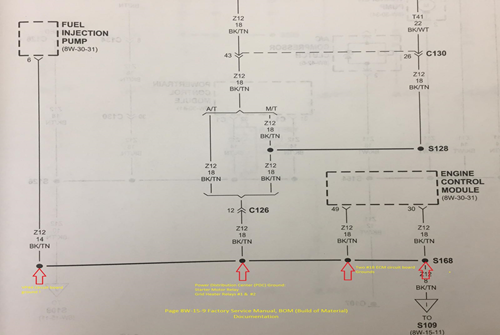
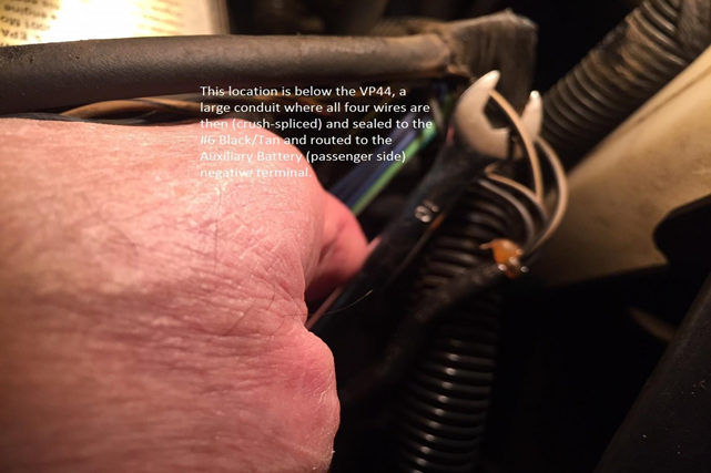
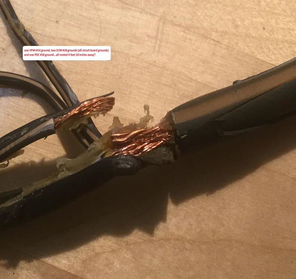
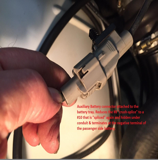
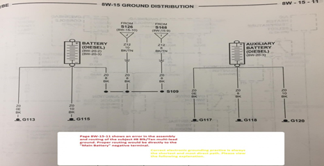
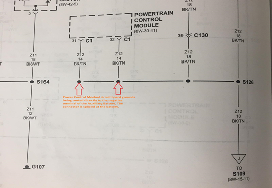
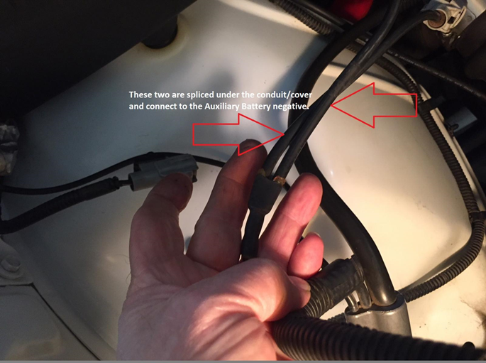
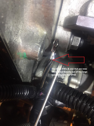
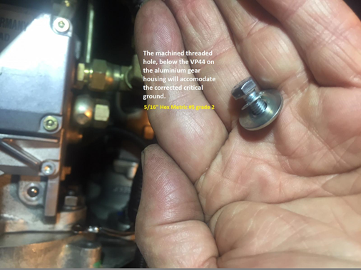
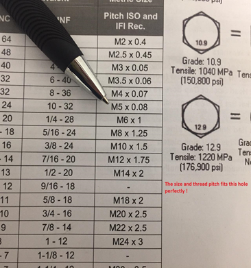
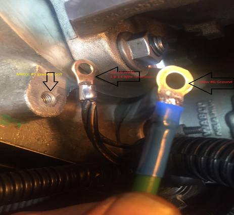
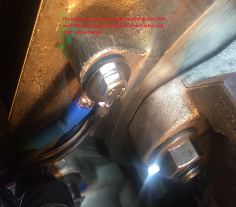
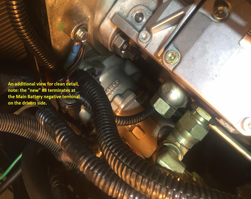
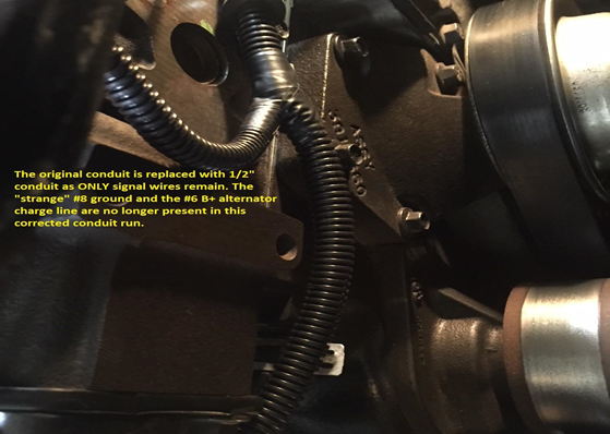
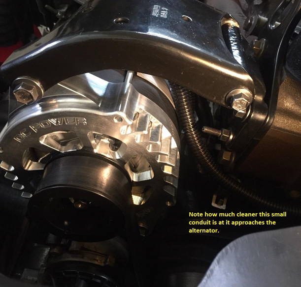
After 18 years of interesting CTD enthusiasts and transmission specialty outlets all contributing their method, or fix, to the well known TC lock unlock syndrome, I can no longer remain silent. Extensive review of many posts regarding TC lock unlock, the rerouting methodes, the add on filters for APPS and last, but not least,...the "tin-foil hat" brigade. I do realize that each individual or company that contributed to the vast amount of information on the web had good intentions and I must acknowledge that some of the procedures caused me to closely examine what these people were trying to do. I believe it is well known that even a blind mouse occasionally finds a morsel of cheese. Again, as it is well known @Mopar1973Man was the only entity who positively identified the instigating source of this key issue. My entry today is not about alternators...it is about what Daimler/Chrysler did in regard to production of these Cummins powered platforms and the complete disregard of common sense Electronic Engineering. Please note, this applies to automatic and manual transmissions as each platform is plagued in the same manor with different quirks. This Blk/Tan #8 gage wire is quite critical in the scheme of things. It is contained within a 1" plastic conduit passing along the front of the engine. It contains water temp sensor leads, air conditioning leads, alternator/PCM leads and the #6 gage alternator charge line to the PDC. This #8 gage Blk/Tan passes over the top/backend of the alternator and is "eventually" connected to the Auxiliary Battery (passenger side) negative terminal. This snapshot of the Factory Service manual documents "four critical ground leads" that are "spliced" in an unconventional method. This photo depicts the three #18 gage wires and the single #14 gage wire entering the shrink-tubing where the "crush-splice" occurs. This bundle exits the large plastic conduit below the VP44 This again is a most disturbing depiction of the Daimler/Chrysler method of splicing critical ground leads and then routing this across the top of the alternator and "eventually" bringing this to ground reference. This photo depicts where this #8 gage Blk/Tan first connects on the way to "eventual" ground...yes this is the Auxiliary Battery tray connector. Please note: it is spliced again and joins the PCM circuit board grounds...which are critical in their own nature...and "eventually" terminate at the negative post of the Auxiliary Battery's negative terminal. This photo is very interesting, it is the Factory Service manual and the assembly line documentation follows this as a road map in the matrix during production. Please NOTE the title "NAME" to each battery...I looked at this for a considerable amount of time before I realized the assembly line coordinators tried to work with the documentation from the Engineering Staff to "make it as it looks"...Could this single oversight be the reason of a four foot ten inch critical ground wire combination traveling the distance to "EVENTUALLY" terminate at ground? From a basic engineering standpoint regarding ground...you "NEVER CHOOSE THE PATH OF EVENTUAL GROUND" !!! It is to be the shortest and most concise connection in reference to ground...this is biblical in ALL ELECTRONICS...including pickup trucks. ! Here is the Factory Service manual documenting the PCM circuit board reference ground starting as a pair of #14 gage wires being spliced into a #10 gage bundle and arriving at the Auxiliary Battery through another connector that joins a #8 gage wire that is "splice-joined" under plastic conduit in a Y configuration joining the rouge #8 gage "after passing over the alternator" traversing the entire engine compartment from the driver side of the vehicle. Seriously I have been drinking excessively, most recently, due to the nature of this blatant discovery. This is the hidden Y splice at the Auxiliary Battery where the "mess" EVENTUALLY terminates for ground reference. This photo shows the correct "HOLE" of where to apply ground for the VP44, ECM and the PDC...note the logical location It took a little research to find the size and proper thread-pitch. Metric M5 with a 5/16" hex head is perfect This is where you apply a fresh "quality" #6 gage ground and terminate this at the Main Battery negative post on the drivers side for absolute ground reference for the VP44 and ECM This is a very short and concise reference to ground. This is the corrected procedure for a rather critical ground. The two largest wires originally contained within the 1 inch conduit are no longer present and located well away from the alternator. My alternator B+ "charge" line is now a #4 gage line directly connected to the Auxiliary Battery and when my new battery terminals arrive and they are secured, I'll provide photos of a completed Master Power Supply System within this engine bay. With these corrections, I would hypothesize that a poor ripple specification on a given alternator would be overcome by the immense capacitance of the parallel batteries and would become less prone to causing the dreaded TC lock/unlock for automatics and cruise-control abnormalities for the manual transmission platforms. The #8 gage Blk/Tan passing over the alternator as an "EVENTUAL" ground is gone...the PCM, ECM, VP44 and the PDC are now grounded in accordance of standard Electronic Engineering practices. Respectfully W-T35 points
-
18 pointsOk I know several members have done this mod and said it was easy. It sure is easy. It takes about 2 hours from start to finish to complete this project. You'll need the terminal lugs and the metric bolt that @W-T specifies in his article. First thing disconnect your batteries. I unhooked the two negative leads. You need to gain access to the loom going across the front of the engine. So you'll need to remove the upper alternator bracket and the the two loom holders on the front of the block. I did this during my coolant flush project so my upper hose and thermostat are removed. If you have my crankcase vent that will need to be removed as well. Now I started at the battery and the alternator and started unhooking the wiring from these devices bring it forward. Now you start working on getting the split loom off the wiring. Start at the tape with a small exacto knife or razor blade and carefully split the tape to release the plastic split loom cover. Carefully remove it. I found out mine was brittle after all the years of engine heat. Once you remove all that slpit loom you can again split the spiral tape holding the loom together. Now you show be able to have both the ground lead and the alternator charge lead loose now. I will admit the alternator lead took a bit of work to release at the knot of tape on mine where it breaks out of the loom heading for the PDC. Just take your time with your razor blade and your get it released. You can clearly see the splice of the ground just like @W-T mentions in his article. Once you get the alternator lead out in one piece. Then the ground lead I used a pair of wire dikes and cut the ground right at the end of the splice. Now the alternator lead I reused the wire since it was in excellent condition. I mocked up the alternator lead by hooking it back up to the alternator like it should be and gave it a nice loop of slack then cut it to meet the positive battery terminal. On my terminal lugs, I took a hacksaw and scored the plastic collars and peeled them off for soldering. Then slipped the lug on and used a propane torch with the low flame and soldered the lugs right on to the wire. Good sold weld and this will seal the wire from future rot from battery acid and vapors. This is the completed alternator connection now. All I did was grab an old nut and stacked on the battery terminal. Now we are going to do the ground side. Now trim back the old splice and free the ends of the wires. Now strip back the wire so you can fit the wires into a lug. Again I did the same thing I took the hacksaw scored the plastic collar and peeled it off the lug and then slipped it on the wires and prepped it for soldering. Again just slipped the lug on the wires and low flame with a propane torch I soldered the lug to the wires. Now I cut the old plug off the splice on the passenger side ground and then trimmed the length of the wire with the plug so it would reach between the driver side battery and the gear case. Same again I peeled the plastic collar and slipped the lugs on and soldered with low flame propane torch. This gives you an idea where the wires go. Take your metric bolt and attach the ground wires to the case. Then the ground cable to the negative battery terminal on the driver side. Beyond this is just clean up. Now you need to tape up your loom again. I'm going to replace my split loom with a smaller size being the old loom was brittle and was breaking during removal. The only thing that should run across the front of the engine now should be the ECT sensor which is a twisted pair. The A/C compressor, A/C high-pressure switch, and the alternator field lead. Before AC noise level was 0.038 AC volts now after the mod its dropped to 0.015 AC volts (or 15mV AC). About the parallel cables... There is lot of folks being told they NEED the parallel the positive and negative cables. To test if you need that or not. Take a good quality DVM meter capable of DC mV scale. Now place a Black probe on the battery terminal and the red probe on the block (clean metal). Typically I see 3mV (0.003 volts) after doing the other part of the ground wire mod. Now take a set of jumper cables and go from the negative post to negative post. Also check the AC noise voltage with the jumper cable hooked up if there is no real change then you do not require the parallel cables. If the voltage drop is the same with the jump cables then you do not require the parallel cables because there are ZERO improvements. You can do this on the positive side as well. If there is a voltage change my first thought is to replace the BAD cables first before paralleling on a bad cable. All you do is covering up a bad connection. Adding the extra cables will not improve anything if it's not changing the voltage drop from point to point. Addon: Protection fuse or fusible link Some members are suggesting to install a fusible link or fuse of the same size at 140 Amps on the charge lead as a protection method. Just in case for some reason the diode bridge happens to short the positive side to the ground and doesn't start an engine fire. As for the size of the fusible link is still unknown as of yet. The factory is 140 amp fuse. The fusible link would be better suited than a fuse. I've found a few trucks that is incapable of doing a circuit breaker because of mystery loads and causing the breaker to trip prematurely. Fuse will solve this problem but make sure to carry an extra fuse. Addon: Resettable Circuit Breaker I picked up an inexpensive 150A circuit breaker from Amazon. The breaker does the job but over time the breaker will get weak and trip prematurely. I still favor the circuit breaker over a fuse for the alternator protection. Fuses you might go through several and be left high and dry without a spare and unable to drive home. Make sure you buy plenty of spare fuses if you go that route. Even with my backcountry travels I still trust the circuit breaker better.18 points
-
17 pointsGot it back tonight... man it feels good to drive it again. Handed it off to my dad and he's got it locked up in the shop. Insurance adjuster should be out soon to assess the damage and stolen items.
 17 points
 -
14 pointsHappy Thanksgiving to all you guys and your families. But most especially to MoparMom who is such a key ingredient to this Forum. After all she raised a great son who has helped so many of us to keep our trucks going long and strong. I send her my love and hope more of you all get the opportunity to meet her Thanks to all you guys for all the helpful fun posts..14 points
-
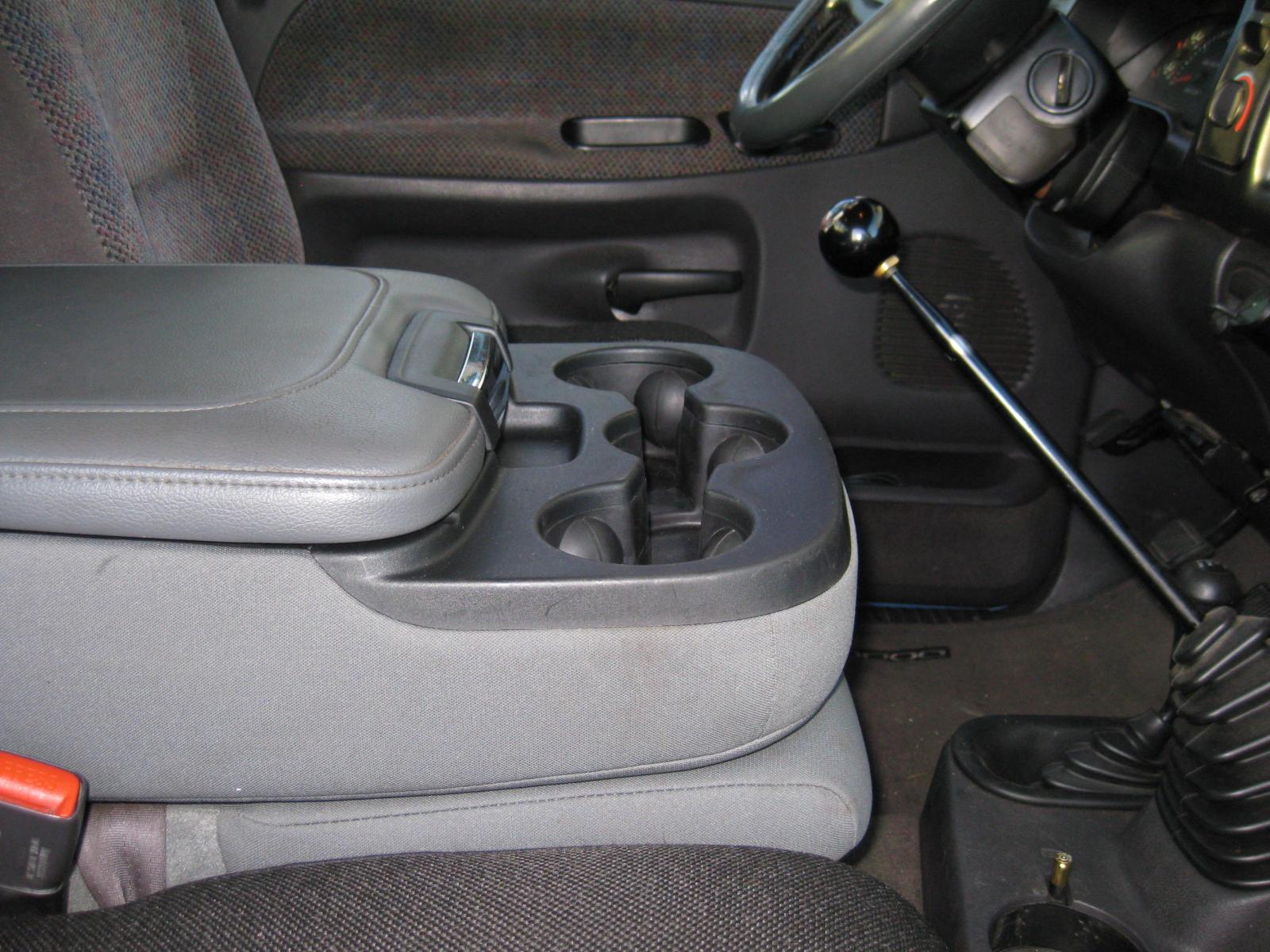
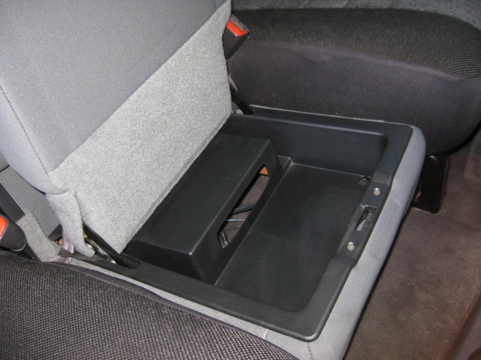
The cup holder from Geno's worked great ....... no complaints! But, this console from a 2011 Dodge works better. Easy to install. The back two mounting holes match up, just drill into the mounting frame for the front two. Sits a little lower than the original, has a little less room, but opens easier and has the electrical 'ports' ..... and a lower compartment below the seat cushion. And again ...... because of the lack of spilled coffee, I'm getting younger, have untold wealth, and never get flat tires!
 14 points
 -
14 points
-
14 pointsHe writes: My lead flight attendant came to me and said, "We have an H.R. On this flight." (H.R. Stands for human remains.) "Are they military?" I asked. > > 'Yes', she said. > > 'Is there an escort?' I asked. > > 'Yes, I've already assigned him a seat'. > > 'Would you please tell him to come to the flight deck. You can board him early," I said.. > > A short while later, a young army sergeant entered the flight deck. He was the image of the perfectly dressed soldier. He introduced himself and I asked him about his soldier. The escorts of these fallen soldiers talk about them as if they are still alive and still with us. > > 'My soldier is on his way back to Virginia ,' he said. He proceeded to answer my questions, but offered no words.> > I asked him if there was anything I could do for him and he said no. I told him that he had the toughest job in the military and that I appreciated the work that he does for the families of our fallen soldiers. The first officer and I got up out of our seats to shake his hand. He left the flight deck to find his seat. > > We completed our pre-flight checks, pushed back and performed an uneventful departure. About 30 minutes into our flight I received a call from the lead flight attendant in the cabin. 'I just found out the family of the soldier we are carrying, is on board', she said. She then proceeded to tell me that the father, mother, wife and 2-year old daughter were escorting their son, husband, and father home. The family was upset because they were unable to see the container that the soldier was in before we left. We were on our way to a major hub at which the family was going to wait four hours for the connecting flight home to Virginia .> > The father of the soldier told the flight attendant that knowing his son was below him in the cargo compartment and being unable to see him was too much for him and the family to bear. He had asked the flight attendant if there was anything that could be done to allow them to see him upon our arrival. The family wanted to be outside by the cargo door to watch the soldier being taken off the airplane. I could hear the desperation in the flight attendants voice when she asked me if there was anything I could do. 'I'm on it', I said. I told her that I would get back to her.> > Airborne communication with my company normally occurs in the form of > e-mail like messages. I decided to bypass this system and contact my flight dispatcher directly on a Secondary radio. There is a radio operator in the operations control center who connects you to the telephone of the dispatcher. I was in direct contact with the dispatcher. I explained the situation I had on board with the family and what it was the family wanted. He said he understood and that he would get back to me.> > Two hours went by and I had not heard from the dispatcher. We were > going to get busy soon and I needed to know what to tell the family. I sent a text message asking for an update. I Saved the return message from the dispatcher and the following is the text:> > 'Captain, sorry it has taken so long to get back to you. There is policy on this now and I had to check on a few things. Upon your arrival a dedicated escort team will meet the aircraft. > The team will escort the family to the ramp and plane side. A van will be used to load the remains with a secondary van for the family. The family will be taken to their departure area and escorted into the terminal where the remains can be seen on the ramp. It is a private area for the family only. When the connecting aircraft arrives, the family will be escorted onto the ramp and plane side to watch the remains being loaded for the final leg home. Captain, most of us here in flight control are veterans.. Please pass our condolences on to the family. Thanks.'I sent a message back telling flight control thanks for a good job. I printed out the message and gave it to the lead flight attendant to pass on to the father. The lead flight attendant was very thankful and told me, 'You have no idea how much this will mean to them.' > > Things started getting busy for the descent, approach and landing. > After landing, we cleared the runway and taxied to the ramp area. The ramp is huge with 15 gates on either side of the alleyway. It is always a busy area with aircraft maneuvering every which way to enter and exit. When we entered the ramp and checked in with the ramp controller, we were told That all traffic was being held for us.> > 'There is a team in place to meet the aircraft', we were told. It > looked like it was all coming together, then I realized that once we turned the seat belt sign off, everyone would stand up at once and delay the family from getting off the airplane. As we approached our gate, I asked the co-pilot to tell the ramp controller we were going to stop short of the gate to make an announcement to the passengers. He did that and the ramp controller said, 'Take your time.'> > I stopped the aircraft and set the parking brake. I pushed the public address button and said, 'Ladies and gentleman, this is your Captain speaking I have stopped short of our gate to make a special announcement. We have a passenger on board who deserves our honor and respect. His Name is Private XXXXXX, a soldier who recently lost his life. Private XXXXXX is under your feet in the cargo hold. Escorting him today is Army Sergeant XXXXXXX. Also, on board are his father, mother, wife, and daughter. Your entire flight crew is asking for all passengers to remain in their seats to allow the family to exit the aircraft first. Thank you.' > > We continued the turn to the gate, came to a stop and started our shutdown procedures. A couple of minutes later I opened the cockpit door. I found the two forward flight attendants crying, something you just do not see. I was told that after we came to a stop, every passenger on the aircraft stayed in their seats, waiting for the family to exit the aircraft. > > When the family got up and gathered their things, a passenger slowly > started to clap his hands. Moments later more passengers joined in and soon the entire aircraft was clapping. Words of 'God Bless You', I'm sorry, thank you, be proud, and other kind words were uttered to the family as they made their way down the aisle and out of the airplane.> > They were escorted down to the ramp to finally be with their loved one. > > Many of the passengers disembarking thanked me for the announcement I had made. They were just words, I told them, I could say them over and over again, but nothing I say will bring back that brave soldier. > > I respectfully ask that all of you reflect on this event and the sacrifices that millions of our men and women have made to ensure our freedom and safety in these USA , Canada , Australia New Zealand, England .> > Foot note: > > I know everyone who has served their country who reads this will have tears in their eyes, including me. > > > They die for me and mine and you and yours and deserve our honor and respect.> > 'Lord, hold our troops in your loving hands. Protect them as they protect us..bless them and their families for the selfless acts they perform for us in our time of need.. In Jesus Name, Amen.' > > GOD BLESS YOU!!!14 points
-
13 pointsDodge/Cummins ECU (1998.5 - 2002 ISB) ECU Hardware There are 2 computers on the Ram. One on the passenger side firewall behind the air cleaner assembly (the Powertrain Control Module, or PCM), and the ECU, which is located on the left side of the engine, mounted directly on the engine block. The ECU is connected with a single 50-pin connector. The ECU itself is a sealed unit, with a single air vent device. It is constructed of an aluminum 'frame', or center section, that has the mounting tabs to fasten it to the engine, and a sheet aluminum 'cover', that isn't really a cover at all - the flexible plastic 'circuit board' is adhered directly to the inside of this 'cover', on both sides. There is gray silicone sealer between the 'cover' and the 'frame'. To open the ECU, one must remove the screws, and carefully pry the cover open. You must be sure to keep the cover straight and don't bend it, as the flexible circuit board is adhered directly to the inside of it. The side of the ECU with the electrical connector seems to contain power supply and other power-switching components (driver transistors, etc). I do not know if there are any ICs on this side, because I did not open mine up on that side (and at this point, I do not really want to). The other side contains the 'computer' components (processor, memory, etc) as shown below: Most of the ICs inside are standard components. There are several unidentified components: 8L12A: 8-pin IC. Possibly 12V voltage regulator for flash programming? Phillips IC, marked '4651148 005633-- Fhr011B'. Maybe analog MUX for ADC inputs? Atmel IC, marled 'ENCORE 51R42722U02 82002253-001 A9D0013 9951'. I have no idea what this is for, it looks like an ASIC. 8-pin IC marked '74690 XAVS' 8-pin IC marked '3029009 1951130'. Near the filter choke. CAN bus driver? The ECU only uses 256KB of flash, even if the installed chip is larger. The original ECU I opened had a 512KB chip (28F400). I later obtained another ECU, and discovered it had a 256KB chip (28F200). These flash chips are organized into a 16KB boot block, 2 8KB parameter blocks, and the remaining blocks are regular data blocks. The parameter blocks can sustain many more read/write cycles than the other blocks on the chip. There is 64k of RAM available, in the 2 32Kx8 SRAM chips. The memory is organized as follows: 0x000000 - 0x3FFFFF: Flash. The first 16k (0x000000 - 0x004000) is the 'boot' part of the flash chip. 0x800000 - 0x80FFFF: RAM 0xFFD000 - 0xFFD7FF: Some unknown peripheral device. Perhaps the Atmel chip? 0xFFD800 - 0xFFDFFF: Intel CAN Controller 0xFFE000 - 0xFFEFFF: TPURAM (Refer to the MC68336 manual) 0xFFF000 - 0xFFFFFF: MC68336 internal functions/integrated peripherals Software Using a BDM interface cable and driver, I wrote a program that would dump the contents of the flash chip to a file for inspection. This was difficult because every so often during the data transfer, an error would occur. I solved this problem by only reading 2KB at a time. I later found out that this read error was occurring because of a 'watchdog timer' in the ECU hardware was attempting to assert RESET while I was reading the data (because when reading through the BDM port, the CPU is stopped). Once I modified the program to do 2KB reads I was able to get a successful read of the data. I used GNU objdump to create an assembler listing of the file. I have spent many hours 'picking apart' the program to figure out what each section is for, how the peripherals of the MC68336 are configured/used, etc. There is a compressed program in the lower 16K (boot block) that gets decompressed into RAM at startup, only if certain conditions are met. This is probably a small program that is only good for reading the CAN bus, so that the flash can be reprogrammed. I have not spent much time examining this program. The VIN of the vehicle is embedded in data around 0x4000, and again around 0x8000. There is also a 'signature' around 0x8000 that is checked at startup, and if it is valid, an address is read from location 0x800a and execution of the 'main' startup code continues at that address. There is a considerable amount of data that gets moved from the end of the flash data into RAM at startup. In this example, the data begins at 0x3829e and ends at 0x3fee7. That is approx. 32KB of data. At this time, I have only been able to identify the startup code, where the various components are initialized and addresses are set up, and parts of the program that read/write the CAN messages. The following things need to be done: Identify the CAN messages themselves, the message contents, and what they mean. Identify which inputs connect to where (temp sensors, MAP, APPS, etc). Identify the other outputs and what ports they are located (Wait to start lamp, VP44 relay, fuel pump relay, intake heaters, etc.) Determine how the flash can be programmed by methods other than desoldering the chip from the board Identify the remaining program sections, and their assocaited data (the 'maps') It would probably be useful to build a CAN interface for my PC, and 'watch' the data on the CAN bus while the engine is in operation. This might yield some information that can be used to identify more of the program. Other information It appears that the ECU itself was designed (and possibly manufactured) by Motorola. The ECU software, is unknown. There is no copyright message or any other identifying information in the dump of the flash memory, except the VIN number and the string '091197'. I do not know what language the program was originally written in, probably C, I really don't think something that large would be written in assembly language. Why? Because it is my truck, my ECU, my flash memory chip, etc. and I have a right to know how it works. And I also have the right to do what I want with it, whether that be drive it, or take the ECU out, sprinkle cheddar cheese on it and bake it in the oven, etc. I think people should be able to understand, and repair if necessary, anything that they own, whether it be a computer, a car, a dishwasher, or a bike.13 points
-
12 pointsINSTALLING PROTECTIVE LIFT PUMP RELAY The life pump is powered through the ECM via pin #15 and #35. Every time the lift pump is energized the power drawn through the ECM causes heat. After a few thousands cycles of start/stops this heating up and cooling down cause’s degradation in the solder joints and failure. Another possible cause of ECM failure is higher than normal amperage load by either a larger capacity lift pump or a failing pump. As a lift pump starts to go bad (wear internally) the AMP load is increased to overcome the resistance. This added power draw can cause the ECM circuit board to overheat and solder joints to open. The lift pump power routed through a relay protects the ECM from power spikes and excessive amperage loads. The power load on the ECM is now less than 200mA. The lift pump circuit is also protected by a dedicated fuse. MATERIALS NEEDED WIRE: 4 colors if possible, size determined by load and distance, see chart. Fuse holder with fuse: AMP rating determined by load. Relay: Bosch type/mini ISO, terminal 87 normally open (NO) with suppressor, AMP rating determined by load. 6 (or more) solderless insulated female spade connector, 6.35 mm (.25”) sized for wire gauge. 2 (or more) solderless insulated male spade connector, 6.35 mm (.25”) sized for wire gauge. 1 (or more) solderless insulated barrel connector, gauge size for fuse holder. 2 ring terminals, one sized for ground wire and the other sized for fuse holder connection. Dielectric grease, for terminal connections. Self-adhering Velcro, for attaching relay to PDC. ¼” protective wire cover or wrap cut to length. TOOLS Wire cutter Wire stripper Crimping tool for solderless connectors, a small pair of Vice-Grips will work. A 13mm and 10mm socket or wrench. Volt, ohm, amp (VOA) meter with 20amp scale. Optional, Soldering gun/iron with rosin core solder LIFT PUMP DRAW TEST Locate the ground wire for the lift pump and place the VOA meter leads in series anywhere between a grounding point and the negative terminal/wire of the lift pump. With the negative VOA lead connected to ground and the positive VOA lead on the negative side of the lift pump turn the meter select to the 20 amp DC scale, turn the ignition key to the on position and the lift pump will run for 5 seconds. Read the amp draw and make note of it. The fuse, relay and wire size will be based on it. In this example we will use a hypothetical draw of 8.6 amps. CHOOSING FUSE SIZE Finding the correct fuse size is simply multiplying the load in amps times 135% (1.35). In this example 8.6 amps multiplied by 1.35 equals 11.61 amps. The next sized fuse larger than 11.61 amps is 15 so for this example a 15 amp fuse will be used. WIRE SIZE Wire size is based on fuse size and length of wire. The wire has to be able to carry a larger load and not burn up before the fuse does. If the wire gauge is too small for a given distance then the resistance in the wire will cause a drop in voltage. This reduced voltage reaching the lift pump will cause it to run slower and produce less pressure. The voltage not reaching the lift pump is given off as heat. Using the wire gauge chart an 18 AWG is the minimum size used for this example. WHAT RELAY TO USE When an electric motor starts there can be a sharp volt/amp load placed momentarily on the relay contacts so the relay should be rated 2-3 time the motors normal amperage. The motor in this example runs at 8.61 amps times’ 3 equals 25.8 amps so the next size relay that can be used is one rated at 30 amps. The relay of choice is the mini ISO otherwise known as the Bosch type in either 4 or 5 terminal, normally open (NO). Relay terminal 30 is switched power or common in, 87 is switched power out and normally open circuit (NO) when no power is applied to the relay coil. Terminal 86 is the positive or triggering terminal and 85 is the grounding terminal for the relay coil, check relay wire diagram for specific applications. Terminal 87a is normally closed (NC) when no power is applied to the relay coil. If you find a relay marked 20/30 this means terminal 87a is rated for 20 amps and terminal is rated for 30 amps. Using a relay with a built in voltage suppressor is a must. The relay will have a resistor or diode in parallel with the relay coil. This suppressor reduces the back flowing voltage spikes to the ECM when the power to the relay is shut off and the magnetic field around the coil collapses. Most relays denote the use of a suppressor with a symbol of a resistor or diode in the wiring diagram printed or etched into the relay cover. Pay extra attention to the +,- of pins #85 and 86 when installing a relay with a suppressing diode, if not installed properly the relay can be damaged. Napa relay part #ECH AR272 is ratted for 30 amps and has a resistor suppressor. INSTALLATION INSTRUCTIONS OPTION A First disconnect the batteries. Now determine where to place the relay. The relay can be placed on the PDC with Velcro, my Edge EZ has been mounted to the PDC this way for over 12 years. This will keep the electric components in one area, a shorter wire run for relay terminal 30 and no holes in the metal where rust can start. Do not put a screw through the PDC housing; there is the risk of wire or component damage. The source of the constant 12volt power can be either the positive terminal of the left battery or for a neater installation use the large cable stud in the PDC. Install one end of the fuse holder using an appropriate sized ring terminal to the 12 volt terminal and with an insulated female spade connector attach the other end to relay terminal 30. If the wire for the fuse holder is to short connect extra length with either an insulated barrel connector or solder them together and insulate with heat shrink tubing. Find the wire harness used for the lift pump, pulling back the protective wire wrap there will be a yellow wire with white tracer (yl/wt) and a factory connector. This is the factory lift pump power supply and will be used as the ‘trigger’ to open and close the relay contacts. The power source can be verified by attaching a test light or volt meter to it and turning the ignition key to the on position, there will be 12 volts for 5 seconds. The yl/wt wire can be cut 2½”-3”from the factory connector. NOTE this is another place where an amp lode test could be performed. Connect the new correct size wire with either male/female insulated spade connectors, insulated barrel connector or solder/heat shrink to the end coming from the ECM. Attach the other end of the new wire to relay terminal 86 with an insulated female spade connector. Consult relay diagram if diode protected. Connect another new wire to relay terminal 87 with an insulated female spade connector and the other end of the wire to either the factory connector where the yl/wt wire was cut or to the lift pump itself. The picture above shows new insulated spade connectors, the wire on the left is from the ECM to terminal 86 and the wire on the right is from terminal 87 to the lift pump. The relay grounding wire is attached to relay terminal 85 with an insulated female spade connector and the other end using a ring connector to the body. The bolt that holds the PDC to the inner fender is a good spot. Reconnect batteries and test. When routing wires take care that they are kept away from moving parts, ie: steering column, have enough length so as not to pull loose and are covered with protective wire cover or wrap. Use dielectric grease on connections to keep corrosion to a minimum or solder and seal with heat shrink tube. INSTALLATION ISTRUCTION OPTION B The relay and fuse can be installed in the PDC giving it the appearance of an OEM part. Some of the connectors used in the PDC are not available in the general market but can be found in an auto/truck salvage yard. I went to a ‘pick your part’ type salvage yard and found a 1999 Ram 1500 with V8. The PDC is basically the same as my 2000 diesel. You can either buy the whole PDC or remove the terminals with wires attached that will be needed. Leave as much wire as possible; the excess can be trimmed later. Disconnect connect the battery, remove the PDC cover and locate where a spare fuse and relay can be added. Remove the two sheet metal screws (10mm socket) and lift the PDC up. The PDC housing can now be opened by gently lifting the plastic clips on the sides and prying it apart. Now the bottom of the top half is exposed. Drill a hole large enough for three wires to pass through in the lower half of the case. This is where the wires for relay terminals 85, 86 and 87 will exit the PDC. The additional wire length is added by soldering and heat shrink tubing or insulated barrel connector to the used OEM connectors. These connections will be protected in the lower half of the PDC. Pass the wires through the hole and place the salvaged connectors into their appropriate relay slots. The other end of the wires can now be trimmed to length and connected as described in the installation instructions option a above. Place the 2 halves of the PDC together and remount the PDC to the inner fender while grounding the relay terminal 85 wire with one of the screws, reconnect battery and test. My truck lift fuel pump amp draw is 6.5 amps so at 135% protection needed is 8.77 amps, next standard size fuse is 10 amps. Relay size is 3 x 6.5 amps = 19.5 amps so a 20amp rated relay is needed. I used a micro relay which is half the size of a mini relay because it can handle 20 amps and there were 4 empty positions I could put it in verses 1 position for a mini relay in the PDC. I put the relay in a spot marked for an O₂ heater. My truck has a Fuel Boss mechanical fuel pump and I have this electric pump as a backup so I run the engine with the 10amp fuse in the glove box. With a fuel pump relay the fuel system can be primed without the ignition key being turned to the on position by jumping relay terminal 30 to 87. As long as the two terminals are connected the fuel pump will run. Written by: J. Daniel Martin, Martin’s Mobile Maintenance AKA: IBMobile 3/2/201712 points
-
After 18 years of interesting CTD enthusiasts and transmission specialty outlets all contributing their method, or fix, to the well known TC lock unlock syndrome, I can no longer remain silent. Extensive review of many posts regarding TC lock unlock, the rerouting methodes, the add on filters for APPS and last, but not least,...the "tin-foil hat" brigade. I do realize that each individual or company that contributed to the vast amount of information on the web had good intentions and I must acknowledge that some of the procedures caused me to closely examine what these people were trying to do. I believe it is well known that even a blind mouse occasionally finds a morsel of cheese. Again, as it is well known @Mopar1973Man was the only entity who positively identified the instigating source of this key issue. My entry today is not about alternators...it is about what Daimler/Chrysler did in regard to production of these Cummins powered platforms and the complete disregard of common sense Electronic Engineering. Please note, this applies to automatic and manual transmissions as each platform is plagued in the same manor with different quirks. This Blk/Tan #8 gage wire is quite critical in the scheme of things. It is contained within a 1" plastic conduit passing along the front of the engine. It contains water temp sensor leads, air conditioning leads, alternator/PCM leads and the #6 gage alternator charge line to the PDC. This #8 gage Blk/Tan passes over the top/backend of the alternator and is "eventually" connected to the Auxiliary Battery (passenger side) negative terminal. This snapshot of the Factory Service manual documents "four critical ground leads" that are "spliced" in an unconventional method. This photo depicts the three #18 gage wires and the single #14 gage wire entering the shrink-tubing where the "crush-splice" occurs. This bundle exits the large plastic conduit below the VP44 This again is a most disturbing depiction of the Daimler/Chrysler method of splicing critical ground leads and then routing this across the top of the alternator and "eventually" bringing this to ground reference. This photo depicts where this #8 gage Blk/Tan first connects on the way to "eventual" ground...yes this is the Auxiliary Battery tray connector. Please note: it is spliced again and joins the PCM circuit board grounds...which are critical in their own nature...and "eventually" terminate at the negative post of the Auxiliary Battery's negative terminal. This photo is very interesting, it is the Factory Service manual and the assembly line documentation follows this as a road map in the matrix during production. Please NOTE the title "NAME" to each battery...I looked at this for a considerable amount of time before I realized the assembly line coordinators tried to work with the documentation from the Engineering Staff to "make it as it looks"...Could this single oversight be the reason of a four foot ten inch critical ground wire combination traveling the distance to "EVENTUALLY" terminate at ground? From a basic engineering standpoint regarding ground...you "NEVER CHOOSE THE PATH OF EVENTUAL GROUND" !!! It is to be the shortest and most concise connection in reference to ground...this is biblical in ALL ELECTRONICS...including pickup trucks. ! Here is the Factory Service manual documenting the PCM circuit board reference ground starting as a pair of #14 gage wires being spliced into a #10 gage bundle and arriving at the Auxiliary Battery through another connector that joins a #8 gage wire that is "splice-joined" under plastic conduit in a Y configuration joining the rouge #8 gage "after passing over the alternator" traversing the entire engine compartment from the driver side of the vehicle. Seriously I have been drinking excessively, most recently, due to the nature of this blatant discovery. This is the hidden Y splice at the Auxiliary Battery where the "mess" EVENTUALLY terminates for ground reference. This photo shows the correct "HOLE" of where to apply ground for the VP44, ECM and the PDC...note the logical location It took a little research to find the size and proper thread-pitch. Metric M5 with a 5/16" hex head is perfect This is where you apply a fresh "quality" #6 gage ground and terminate this at the Main Battery negative post on the drivers side for absolute ground reference for the VP44 and ECM This is a very short and concise reference to ground. This is the corrected procedure for a rather critical ground. The two largest wires originally contained within the 1 inch conduit are no longer present and located well away from the alternator. My alternator B+ "charge" line is now a #4 gage line directly connected to the Auxiliary Battery and when my new battery terminals arrive and they are secured, I'll provide photos of a completed Master Power Supply System within this engine bay. With these corrections, I would hypothesize that a poor ripple specification on a given alternator would be overcome by the immense capacitance of the parallel batteries and would become less prone to causing the dreaded TC lock/unlock for automatics and cruise-control abnormalities for the manual transmission platforms. The #8 gage Blk/Tan passing over the alternator as an "EVENTUAL" ground is gone...the PCM, ECM, VP44 and the PDC are now grounded in accordance of standard Electronic Engineering practices. Respectfully W-T

 12 points
 -
11 pointsJust have to brag on Mike. Many don't realize just what kind of human being he is. We were just in Winco doing some shopping. We were waiting in line to check out when this little old lady was trying to pay for her groceries...her card was not working...she was almost in tears. Mike paid for it, $269 worth. He simply told her Merry Christmas. The woman was in tears....he is such a kind heart. He struggles to make his own bills every month, and still did this. I'm in tears writing this...11 points
-
11 points
-
OK Guy's.."The moment you've all been waiting for" Here is a complete start to finish Details on Converting Standard 2-headlight system to a Sport Quad headlight sys. i did a few months ago Let me tell you it was a P.I.T.A...i had nothing to go on as none of the threads i found on any of the forums involved building your own from scratch "w/Heavy Duty Stuff" ..most of the write ups were people who had bought a pre-wired harness..like the ones for example suvlights.com or others..all reported problems either "fog lights staying on..lights would not turn off, lights would not come on or lights were dim on bright, etc... So not finding any information in relation to a possiable wiring diagram i purchased a "pre-made harness w/relays from LMC..What a piece of shi$$..i mean lets totally forget that it did not work,{ lights went out or "almost out on Dimm}...this was chineese junk a frigg'n fire hazzard. .cheap light gauge wire i could bite into. connectors that "pulled out after unplugged a time or two..and last but not least.."NO SOLDERED CONNECTIONS, ALL CRIMPED AND "NO HEAT SHRINK. See none of these aftermarket harness's will work on these Trucks neither the Chinese "JUNK" nor the other decent harness's...."WHY" you ask... ..Because no one { that i was able to find } has been able or have taken the time to "Crack This system" and build a precise fit "PLUG AND PLAY" HARNESS ". The 2nd GEN Dodges have a ODD wiring system, I Call it {for lack of a better term} Ground Switching System because thats what it does. It switches the ground Neg- instead of the POS+.. The original wiring has a hot wire to Headlight plug that HOT 24/7..all the time. SO..after tryin to get around it..I started designing & building my own system. and with much help from..MICHAEL "MOPAR MAN" i eventually completed my own system.."NOW..Im passing this information on to you guys because the lights on these trucks "SUCK"..and this is an Awesome improvment that....well ..you will have to see for your self.....AND......I DONT WANT NO ONE TO GO THRU WHAT I WENT THRU BUILDING MINE ..L.M.A.O. ***note*** I soldered all my connections & used heat shrink tubing to make a moisture free system. I also harnessed all the wires in split wire loom conduit thanks Michael Check out link below: Slideshow http://s1209.photobucket.com/albums/cc389/rburks1/Dodge%20Sport%20Quad%20Headlight%20Conversion/?albumview=slideshow Pictures http://s1209.photobucket.com/albums/cc389/rburks1/Dodge%20Sport%20Quad%20Headlight%20Conversion/ Below is the Parts list complete with part numbers & prices. except for the fuse holders, I got most all parts from you can find these parts at most auto or electronic's stores and they don't have to be these brands either but i suggest using quality relays w/holders to make replacement easy. COMPLETE PARTS LIST for HD HEADLIGHT HARNESS (sport HL) ***note*** This Parts list is for reference only.. Vendor, Manufacture & Brands are open to your preference 2-male headlight connector (same as bulb)............................................#CP9004CM..............7.49ea. 2- Ceramic female 9004 Connectors #CP9007CFC.............7.49ea 2-Ceramic female 9007 Connectors.......................................................#CP9004CFC.............7.49ea . 4-HELLA SPST Relays, 40A, Dual 87 outs, .............................................#HL87483...............8.00ea. **Option** 4-SPST HELLA Relays, 40AMP, Dual 87 outs, with Diode.............................#HL87753..........13.00ea. NO LONGER AVAILABLE **Option** 4-SPST HELLA Relays, 30AMP, Dual 87 outs, with Diode..............................#HL87453..........8.00ea. Available @ ralleylights.com ****** Note******* It is not mandatory to use the ones with diodes or resistors, it just helps insure safety for stereo sys, CB & The entire electronic system from EF Feedback.. You could use 30amp relays as you are using separate low and high beam circuits. In the beginning i was originally trying to use only 2 Relays, 1 on each side. I found out later this to be "IMPOSSIBLE" . YOU MUST HAVE 4-RELAYS.. You can use ones with single 87 out and wire together,, the Dual 87 out just makes a nice clean wiring system and i hat cobbled up wiring 4-Relay Holders, complete with terminals....................................................#HL87123.................3.77ea. I Strongly recommend using Holders, it will make changing a relay out as easy as changing a fuse if you should ever have to I got the fuse holders from Advance Auto....."Bussmann Inline, 12ga. wires............#BP/HUU...................5.49ea. I got the Dodge OEM Sport Headlight assembly's @ http://www.factorymopar.com they are a Dodge dealer with online OEM parts. there prices are way below local Dealership. Sport Headlight Assembly's : price= 233.64.. left side 225.38 ..right side There are Cheeper Options for the The Sport Headlights but be forewarned of the cheap knockoffs and there problems like "leaking", , not very good fitment or alignment, ,poor quality Adjusters that make adjustment difficult or impossible>>> "This is important cause you will have to dial these in and insure the Beam is to the left on LOW BEAM Driver side as to keep from blinding oncoming Cars. "The OEM Lights are pretty close out of the box ".. A salvage yard would probably be a good source if you could find any thats not damaged. **UPDATE PLEASE READ ** I have had several Guys PM me asking why is it that there HB indicator light stays burning even on LB...most of the time this issue is caused by wires being in wrong location on one of the Headlight plugs . A weak GROUND circuit will also cause this, You have to have a solid -GND circuit to the Headlight connectors. I used the spare Side post Terminal's on my OPTMA RED TOP BATTERIES POS+ & GND - post. BUT: There is a Post on front inner fender just below the Battery, there is a Solid 8# wire that runs from there that goes to Neg- post battery terminal on battery so this is as good as going straight to Neg without having a bunch of wires hanging off of your Battery causing mores battery issues in the future.. But first be sure it is solid and clean,, if not solid and free from corrosion then replace it. The other cause would be that you have a wire in the wrong place on the back of one or more H L connectors or in the conversion plug itself. Dodge sport Quad headlight conversion.doc Dodge Sport Quad Headlight Conversion- Relays.doc
 11 points
 -
11 pointsAwesome news. My right kidney is healing. Ultra sound shows is not as swollen and there is hope. No surgery required today.11 points
-
11 pointsMike, Truly my pleasure! You do more for people with no expectation of anything in return than 99% of the people on this planet. I have not always been in a position to financially help others in my life but I am currently blessed enough to do so and helping someone like you is a given in my world. I talked with others here after I spoke to the machine shop and I think others would like to participate in helping you in a tight/tough time. I don't see you as one looking for handouts but maybe we could set something up on the website for others who feel as I do about you and the value of the site. I wish I could have paid that whole bill for you, you always answer with Grace my dumbest of questions and have helped me and I am sure many others here through the simple and tough questions. I ask all members that Mike has helped save $20-$1000'S to pay it forward. Many small contributions will make a BIG difference. Mike I ask that you recommend that machine shop to any and everyone in your area!! Great group of guys to help me. If I need a head rebuilt I might just ship it to them. Happy to be able to help a man who has helped me directly and indirectly more than he will ever know. THANK YOU MIKE!! Brian11 points
-
11 pointsHere you go gang! I compiled a full wiring diagram PDF file for you to all enjoy for your 2002 Dodge Trucks. This is a heck of alot easier to read compared to the Dodge FSM manual that is just good old black and white. Go here to get it! https://mopar1973man.com/cummins/articles.html/24-valve-2nd-generation_50/51_engine/electrical/11 points
-
Part 2 I wish to apologize for my absence and attempt to clear some of the stress I may have created. Members @GSP7 and @Dodgeih, my humble and sincere apologies. My thanks to Nick @Me78569, @syndicateshop, @IBMobile, @RipnRam99, @dripley and @JAG1 for filling in the blanks during my absence regarding this lengthy posted subject matter. I'm nearing retirement and I'll be more expedient in the near future. This thread is a focus to remedy the tragic TC Lock/UnLock syndrome and it does tie into the alternator issues bestowed to all 2nd Gen CTD owners. The Godfather @Mopar1973Manis the one who deserves the recognition in this thread. The following photos should suffice in rendering clarity to the "procedures" required to accomplish the the task. Please NOTE: the methods applied are Electronic Engineering standards for high-current demands with ABSOLUTE references to GROUND. The excursions are ONLY for balance (equalization) between two storage batteries in a parallel configuration. This is DONE to allow the Battery Temperature Sensor located on the Main Battery tray (driver side) to be accurate during charge-rate intervals for both batteries. This is accutley important when higher current Alternators are placed into the system. I must emphasize the reasoning: The two batteries are physically separated in distance to accommodate the given engine bay and the Daimler/Chrysler budget to produce the CTD platform. Perfection or "the correct way of doing it" was NEVER a consideration of the manufacturer. I do not wish to continue harping on their oversites...this is what should be done in following the opening portion of this thread. This photo depicts the correct 4 gage conductor directly terminated at the Auxiliary Battery positive terminal. @IBMobile has completed this step and documented his work. This photo documents the "direct" ground from the PCM and fender-ground terminated at the Auxiliary Battery negative terminal. @dripley is very correct in mentioning the "least" amount of connections (splices) should be observed. @IBMobile also accurately documents the "hidden crush-splice" in the wire loom near the PCM where this PCM ground originates. To be a purist, opening this conduit and directly replacing this ground lead with a "clean" 8 gage (or 10 gage) and bringing this directly to the negative terminal would be the best practice. This photo depicts the additional 2/0 Gage lines that "absolutely" strap both storage batteries into compliance of equalization. Again, this excursion (not originally documented in the opening thread) is done for ABSOLUTE integrity between the two storage cells. The "charge" rate from the Alternator supplying the Auxiliary Battery is absolute and mirrored at the Main Battery tray temperature sensor for accuracy. Again, this is most important for those who elected to upgrade the Alternator platform to a higher current device. I would encourage anyone applying this general modification to at least provide, one additional ground strap between the Auxiliary and Main Battery. Do not assume the two 0 gage ground leads to the engine block to provide absolute "ground reference" between the two storage batteries, even, if you remain with the "stock factory" Alternator. The direct 4 gage B+ charge line supplies the Auxiliary Battery first and is in parallel with the Main Battery...the engine block is ground however: for ABSOLUTE ground reference between the two storage cells you should strap an additional ground. The temperature sensor at the Main Battery tray relies on "equalization" between the two cells for sinusoidal charge rates. This photo depicts the Main Battery lines and their perspective terminations. The only excursion here is the replacement of the Starter Motor 2/0 gage supply line. I didn't like the ugly factory line from the front mounting location. This line comes up from the back of the firewall and passes below the PDC box...it certainly cleans up the appearance and provides added accessibility below the VP44 and vacuum/power steering components. Changes like this provide additional serviceability with an artistic flare. This photo depicts the left front fender ground location that terminates at the Main Battery negative terminal. The ugly factory "lug" and sheet metal screw has been replaced with brass components. All connections are below the fender-lip and all paint was removed (Dremel tool grinder) to provide a corrected high-current ground point. Below this connection point are two rather large grounding posts that need attention. The large amount of grounding lines in this corner require some TLC, the method I used provides integrity for DC ground and cleans up the crude slipshod procedure. Besides...mine looks pretty. I should also mention, the brass-to-body connection is treated with conductive grease to eliminate any dissimilar "metal-to-metal" corrosion. @JAG1 has procured the best copper-conductive product available for such purposes and I've not been able to con him out of a few ounces yet. This photo depicts the elected components selected for the heavy current demands in this project. All 2/0 gage line is flexible copper Welding stock...it is very nice to work with and I purchased a modest 12 ton hydraulic "crimper" to apply all zinc-coated connectors as terminations. All shrink-tubing is 3M with internal adhesive for moisture incursion prevention. These beautiful Orion battery connectors provide a very convenient sevicability aspect. Please NOTE the Grid Connection point. Removing the protective caps to expose the connector is very easy ! This is done with Mike @Mopar1973Man in mind to allow the Grids to be disabled for the summer time conditions where Grids are not required. A small Allen wrench is all that is required and can be performed in less than one minute.This photo depicts the graceful run of four 2/0 gage lines across the top of the radiator and artfully draping into position.This depicts a correct Parallel DC storage Battery system created with serviceability in mind.This completes the creation of a DC Power supply worthy of the Cummins platform. The new DC Power Engineering XP270 Alternator with corrected DC ground lines and complementary strapping is exemplary. The performance of a cold morning start was impressive as the Grids fired sequentially without a hint of stress. The "stiff" DC current supplied by the XP270 mimicked a full military hardened assault vehicle under load. I couldn't be more pleased The test drive under warm road conditions yesterday afternoon with particular attention to speed and road conditions showed NO TC lock/unlock syndrome...again win/win. I conclude this saga in humble reverence of the Cummins Turbo Diesel Fraternity in a sharing gesture for all disciples. Cheers, W-T11 points
-
11 pointsSadly, many "built" valve bodies are simply pre-"shift kitted" bodies. And, yes, a "shift kit" will raise your line pressure a bit, and firm up the shifts. That's actually the super easy part. Guys will "kit" their valve body, feel the shifts a little more positively than they did before, and drive off satisfied. And, if that was your goal, then mission accomplished... But these transmissions need quite a bit more pressure than simply putting in a heavier PR spring will give you. This is especially true when guys are using tuners and "chips" to bump their power. While these products are great, and work well, what ends up happening is that your engine will make significantly more power for a given amount of throttle pedal travel that it did with OEM calibrations alone. So, as a result, you end up doing all of your daily driving (your non-"spirited" driving, if you will) with significantly less throttle applied than before. The thing is that your transmission relies on throttle pedal travel (read TV cable movement) to adjust its operating pressure to handle the torque being applied to it. So you end up with a line pressure to torque ratio that is far from favorable. The stiffer PR springs that come in "shift kits" are a step in the right direction in that they do boost line pressure, but it's not nearly enough to reliably handle what you're asking it to do. Developing an optimal pressure curve requires, first of all, an understanding of how these valve bodies control pressure, which is different than pretty much anything else in the transmission world. But suffice it to say that manipulating the hydraulic signals that act on the PR valve is where all of the magic happens in a well built custom valve body. There are several ways to do this, depending upon your end goal, but that's what is necessary to achieve a really good pressure curve. Once you achieve a desirable pressure curve, you will need to deal with the shift and lockup calibrations. If you tried to use stock shift calibrations with an optimal pressure curve, it would, at the very least, be quite unpleasant to drive. Specially designed separator plates with substantially undersized calibration orifices are really the only solution to this dilemma. Again...stuff that a "shift kit" doesn't address. As far as other things a "shift kit" won't give you (at least in a 47RE, which is what we're discussing here), the list would include: ability to lock the converter in any forward gear (including manual 2nd), ability to perform a locked 4-3 downshift, performing an earlier and more positive 3-2 downshift, some cooling and lube control mods, revised boost valve strategy, etc... Why don't I like Transgo in the Chrysler VB? A few reasons... Reason #1: biggest in my book is that they have you grind the land on the switch valve, which effectively removes its ability to regulate converter charge pressure. This is most significant at high throttle settings in reverse, where pressures can easily exceed 250 psi, especially with the stiffer spring you just put in there. This can (and does) balloon torque converters. Reason #2: I don't at all care for the way that they reverse the function of the OD accumulator, and then give you their crappy springs to put in there to try and control OD apply. Personally, with the right calibrations, I find it much easier to control OD apply (especially at high throttle settings) with the OEM style hydraulic accumulator. Reason #3: they remove the function of the part-throttle portion of the 2-3 valve train. This auxiliary portion of the valve body removes TV oil from the 3-2 valve train once a certain amount of governor pressure (road speed) is achieved. I prefer to leave this active for driveability reasons. Reason #4: their manual valve is not nearly as effective as others on the market. I simply do not care for their manual valve. Superior's valve is the best on the market, in my opinion... Sorry for the novel...11 points
-
11 pointsPicture secretly taken this afternoon of Wild and Free moving snow.11 points
-
11 pointsShe made through her surgery last night. Doing good this morning.11 points
-
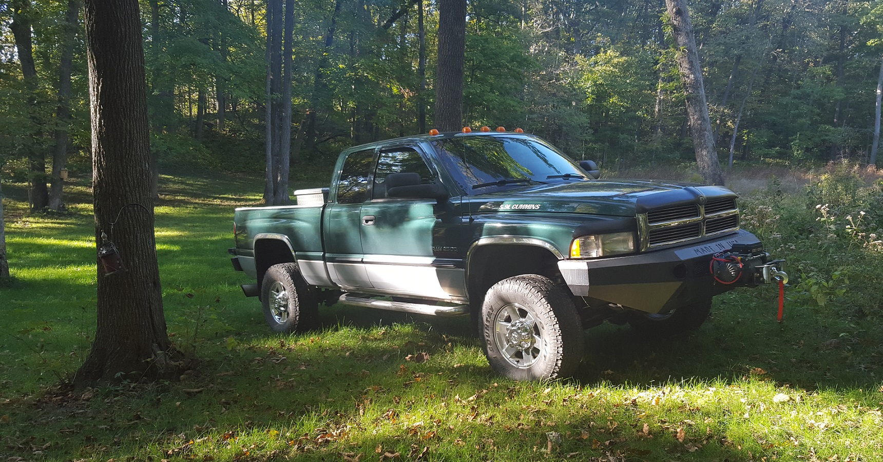
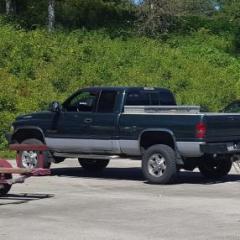
10 points10 points10 points10 points10 points10 points10 pointsHey folks, I haven't posted in a while but i've been around tinkering with 2 out of the 3 2nd gen 24v's that I have. My latest project I've been working on is my red 2001 sport truck I thought I'd share. I got the truck a few months ago and immediately began tearing it apart once I got it to the house. The interior was disgusting and falling apart, typical broken dash, it rattled, there was mold growing on the carpet and it even had maggots under some old food. Here's the progress so far. Torn apart within the first 24 hours of owning it The absolutely disgusting old carpet, I was afraid to even touch it without gloves.. How it turned out after scrubbing it and using a house carpet extractor with the hand hose, went over it twice Got the carpet back in, did a slightly darker dye to get rid of the orange discoloration from the coolant dripping onto the passenger side, This was gone over twice and then I hit the passenger floor for a third time while it was in the truck so it's still slightly damp so it's a little bit darker right now. Put some of the interior back in after a vacuuming as much as I could, the back seat looks brand new! Time to work on the old cracked dashboard! The whole dash frame got taken out, stripped, wiped down of any dirt because i'm very meticulous. If I'm going to work on something, I figure might as well do it right the first time. The LMC dash fit perfectly with no issues at all. At this point in time I figured I was already this close to the HVAC box, I might as well pull it out and clean it! If you look at the blend door at the top right, the foam had mold growing on it, no thank you! More dirt, going to have to clean that! Well, I sure was glad I decided to remove the HVAC box, Leaky heater core, dirty evaporator, bad blower motor, and a crumpling blower motor resistor. Yikes! The entire HVAC box got taken apart, cleaned from top to bottom, and reassembled with all new everything! I even went ahead and pulled off all the old foam and put on a new sealer where the old foam was falling apart. Now that the firewall is cleaned up, time for the HVAC box install. Boom! Put in place and ready to go. Remember the old moldy foam from earlier? All gone, and seals perfectly! The midnight grind, literally... By the morning I had everything put back in and was ready to go. All that work and the dash bezel was still cracked, well, until I FINALLY found a wood grain bezel in 100% perfect condition with no scratches or broken tabs! Out with the old, in with the new! The steering wheel bugged me though so I ended up getting a cover for it. As of last night, I believe she's probably the the truck with the nicest interior. Just need to find some power seats and some agate wood door panels. Maybe do a new steering wheel and definitely need to get a 12v outlet that clips into place nicely. Every piece of the interior got pulled out and cleaned, the cup holders got disassembled and cleaned, including the rear one under the console. This interior is immaculate now. Here's a little bonus for sticking around this long. I also did the 4th gen steering upgrade, as well as a Dodge Off Road Track bar and a steering stabilizer. Big difference coming from the stock setup, Once I got all of it in and took it for a test drive, my power steering was leaking and my water pump went out. That's actually coolant dripping on the ground in the last picture but since then has all been fixed! The wife will be a happy camper driving this until I sell my 99'. Thanks for taking a look! It was a lot of work but I don't regret a single moment of it and will do it again in a heartbeat with the way it turned out.
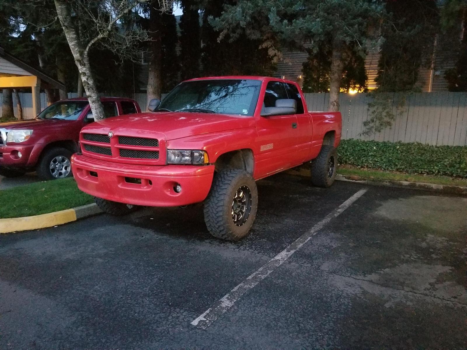
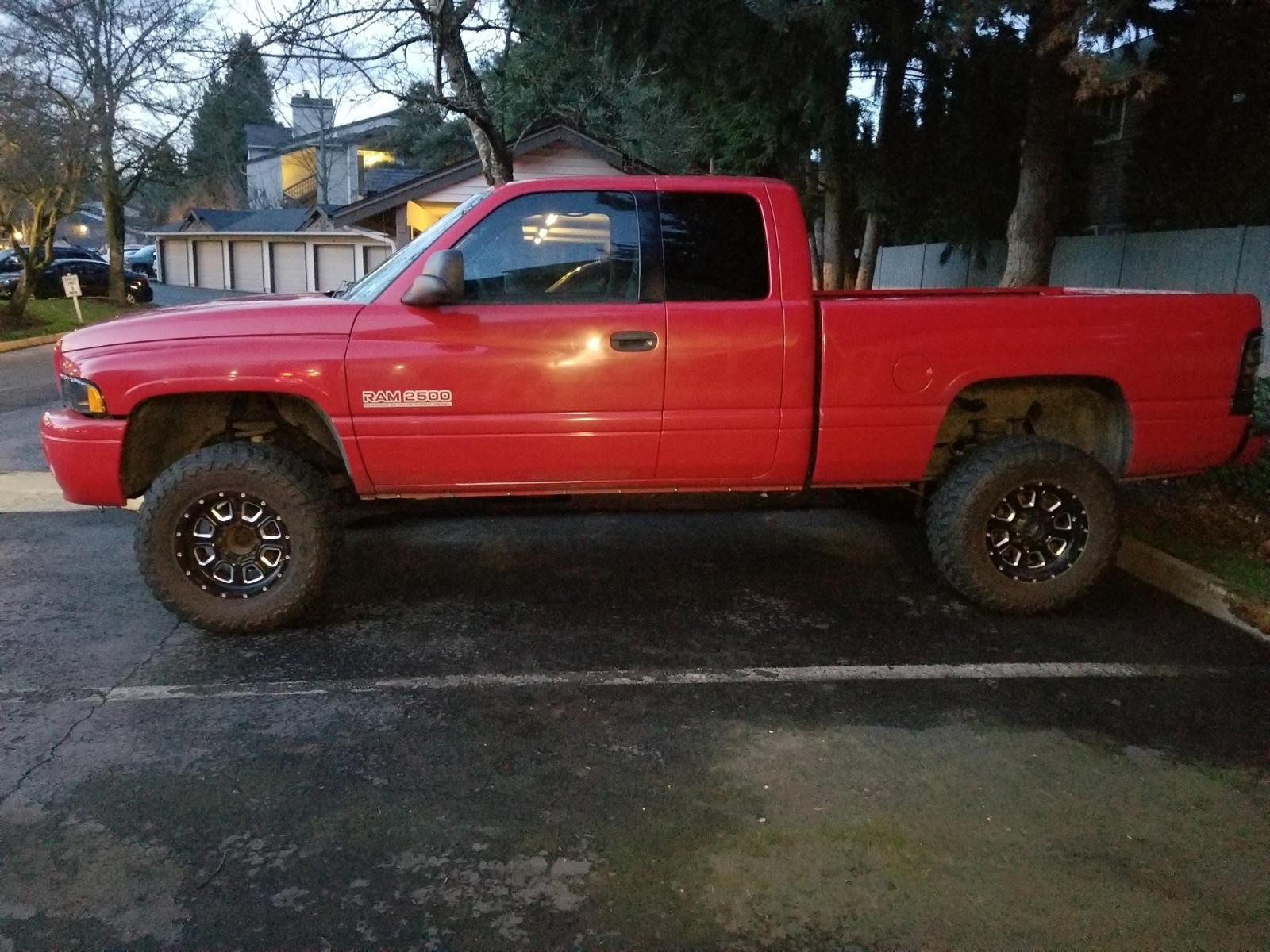
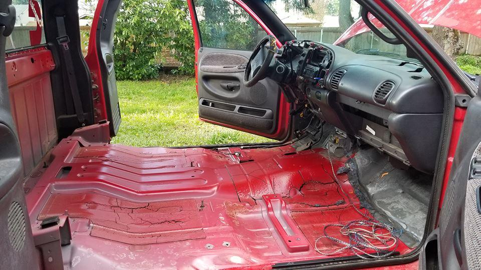
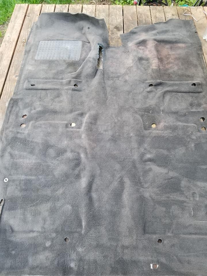
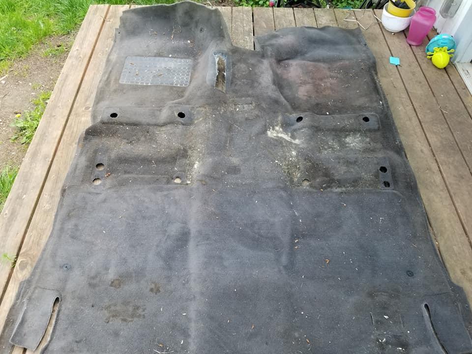
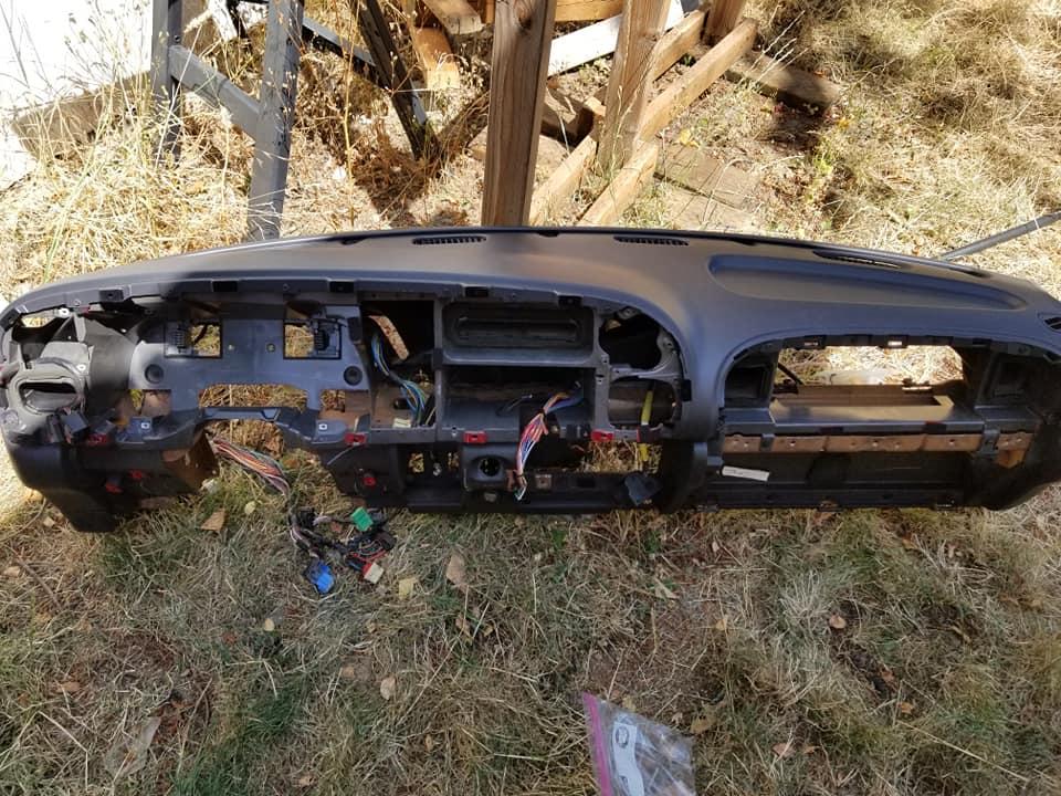
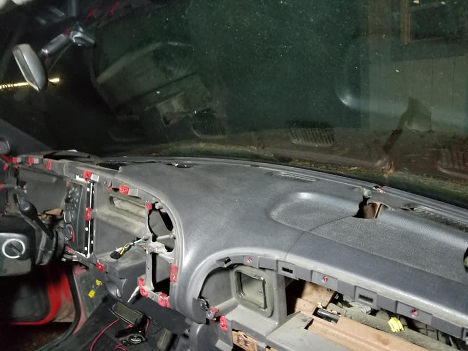
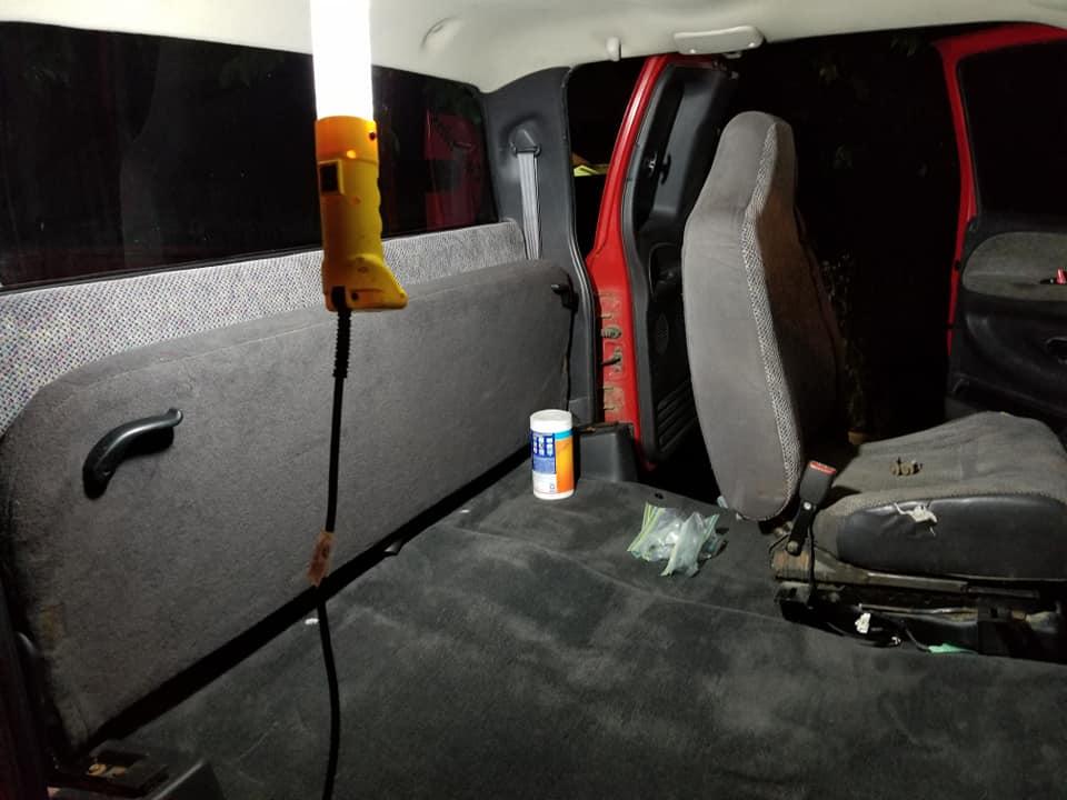
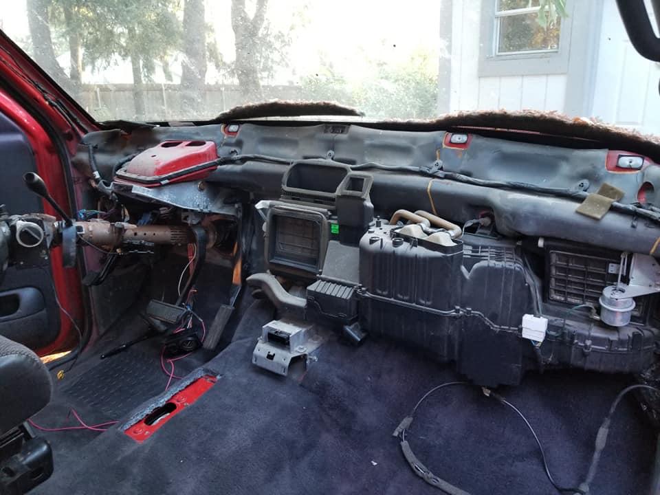
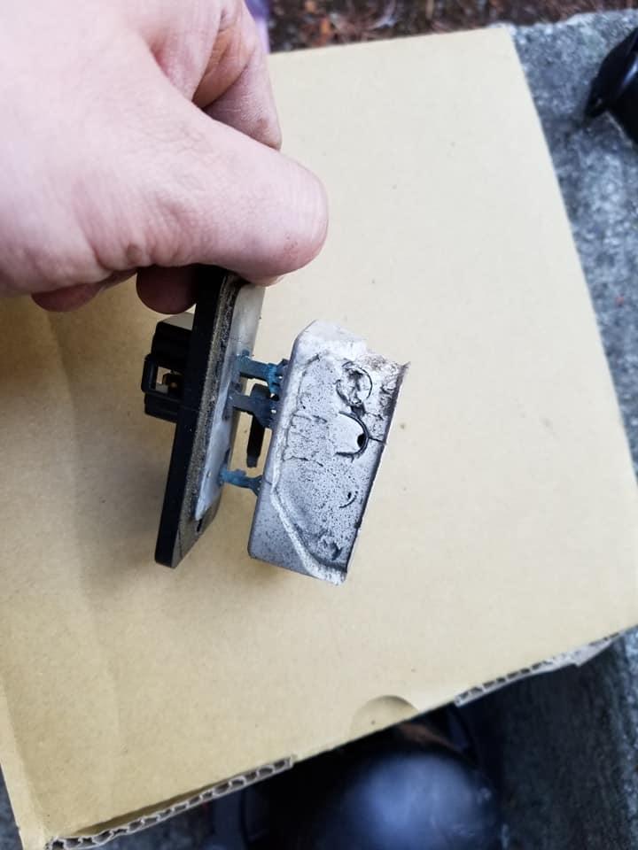
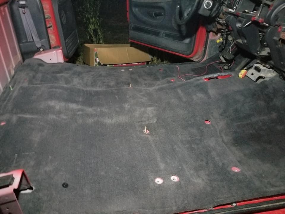
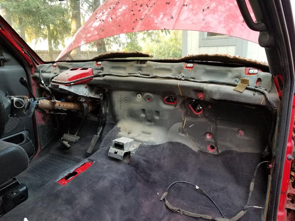
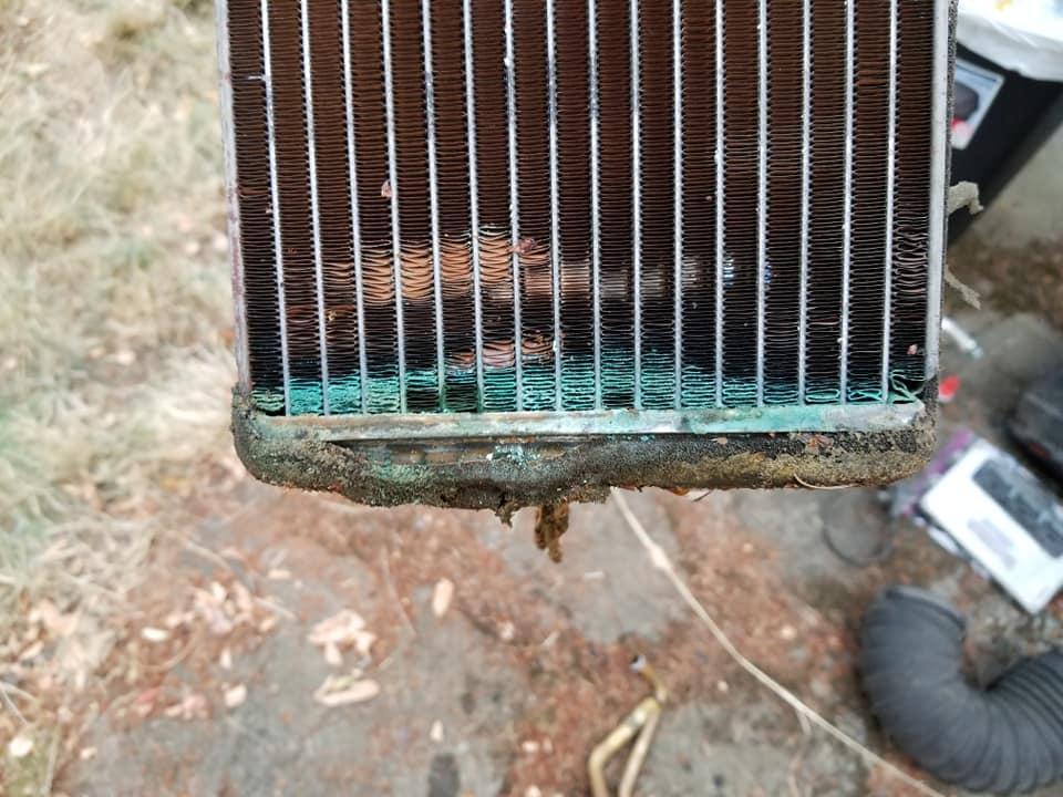
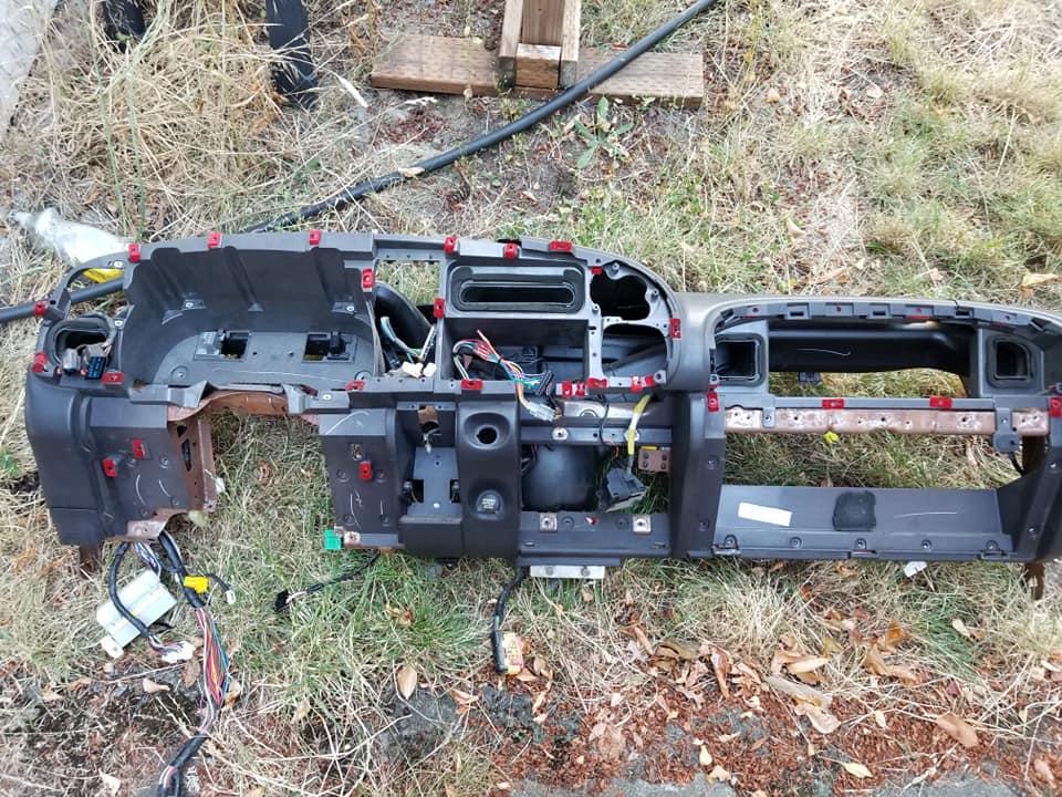
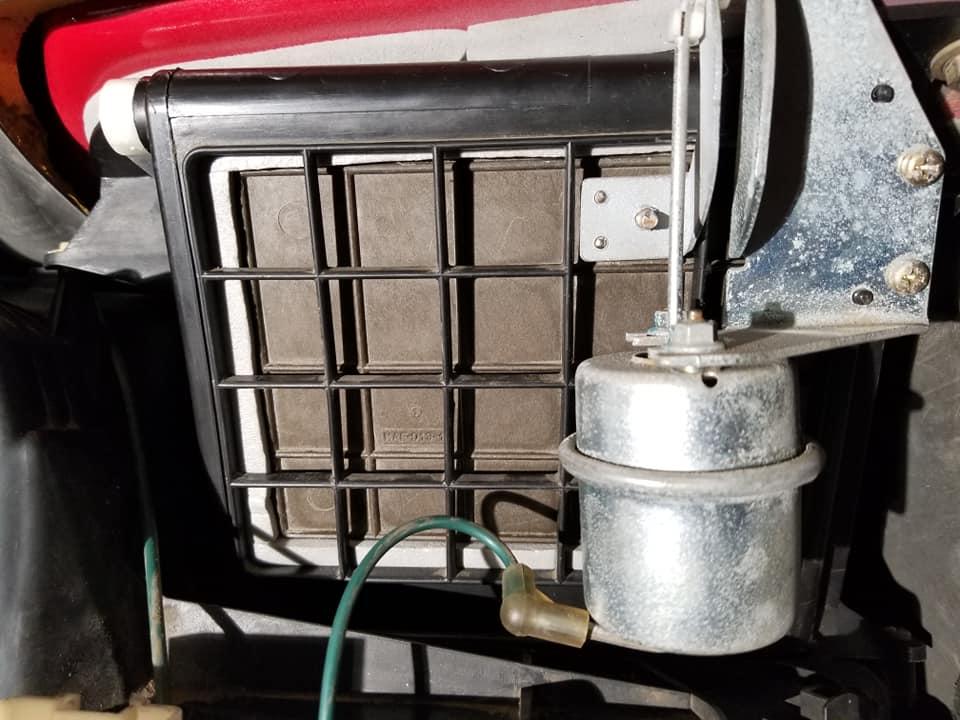
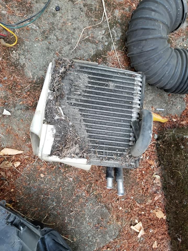
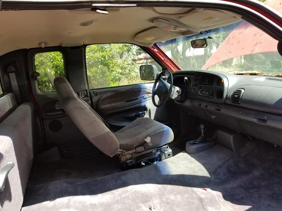
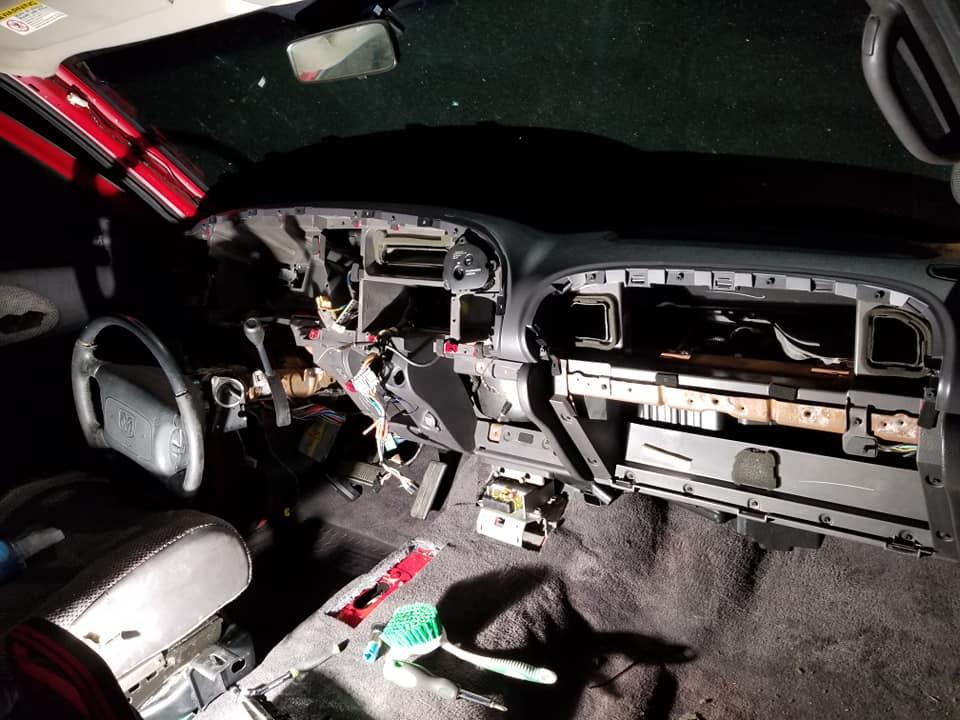

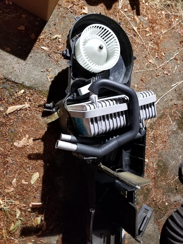
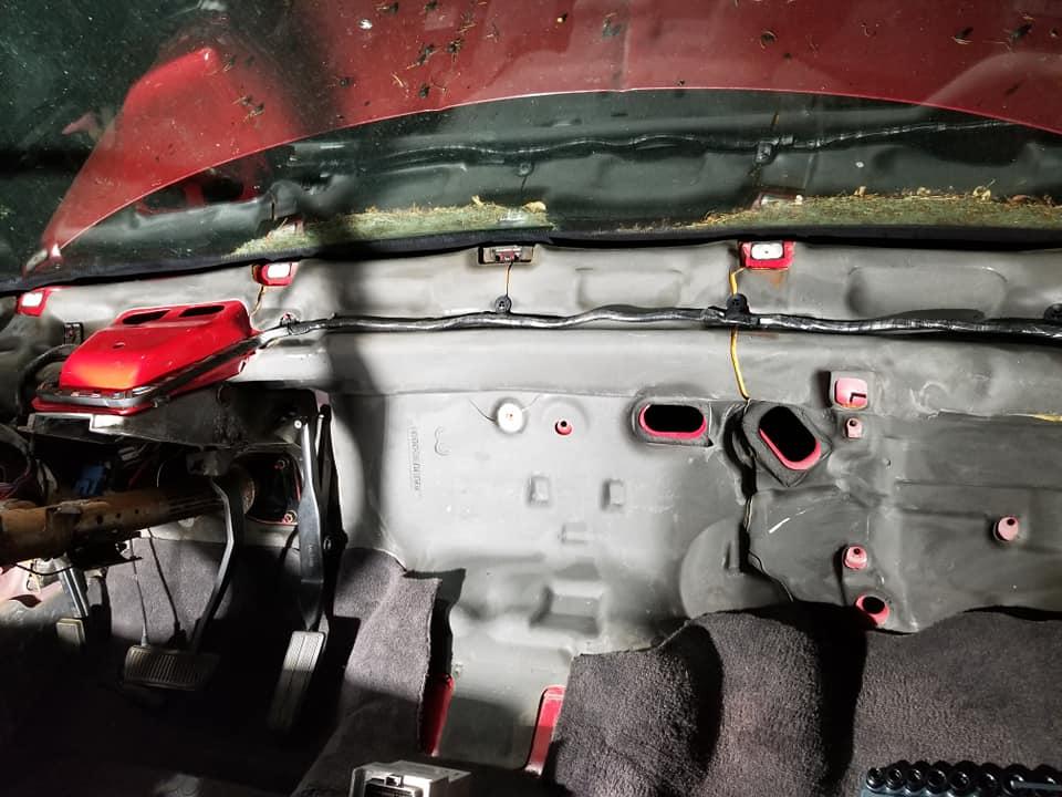
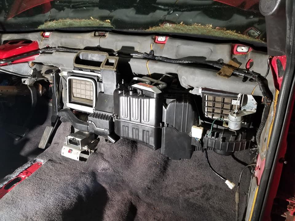
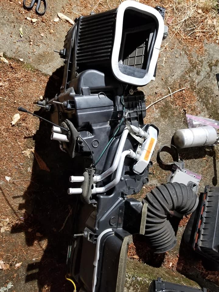
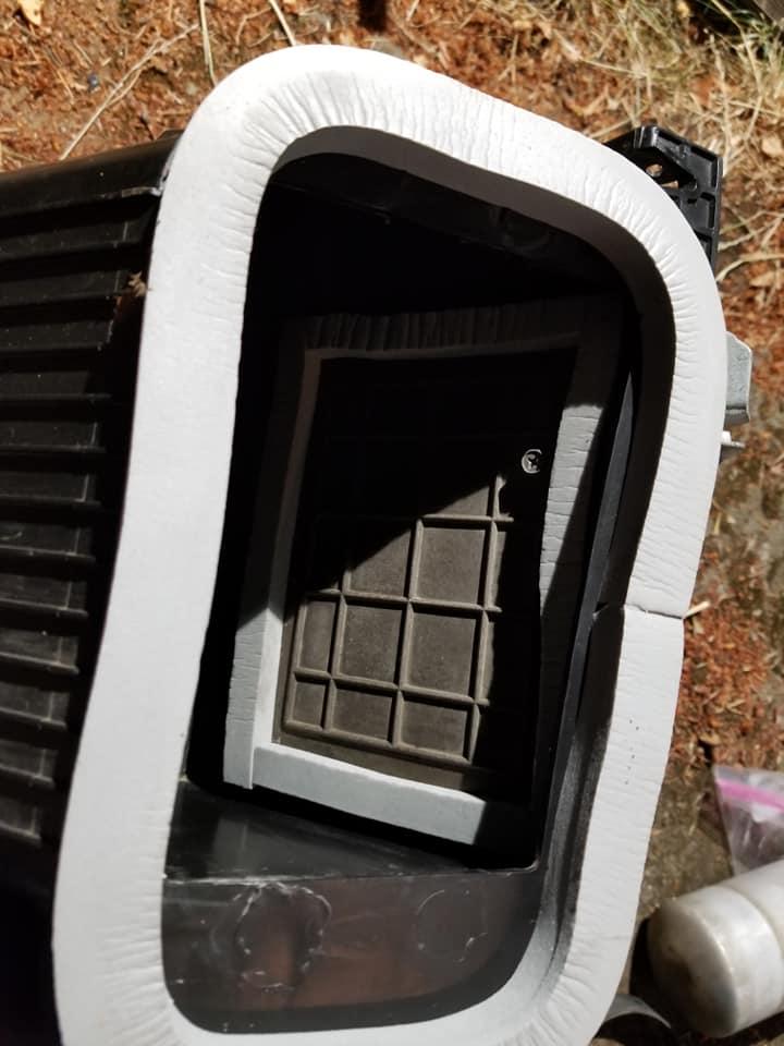
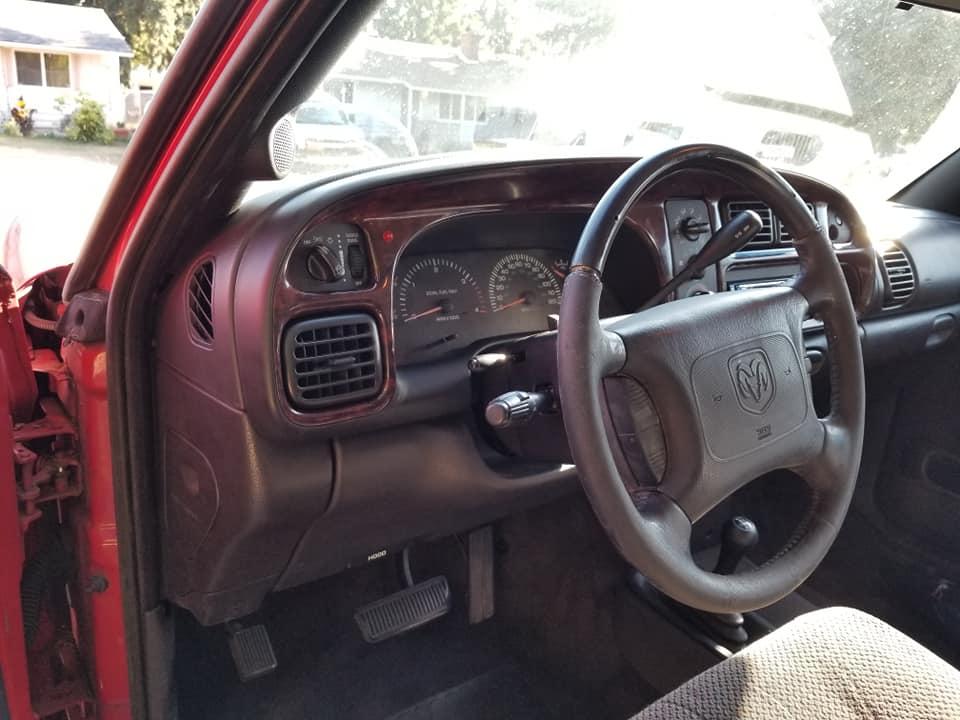
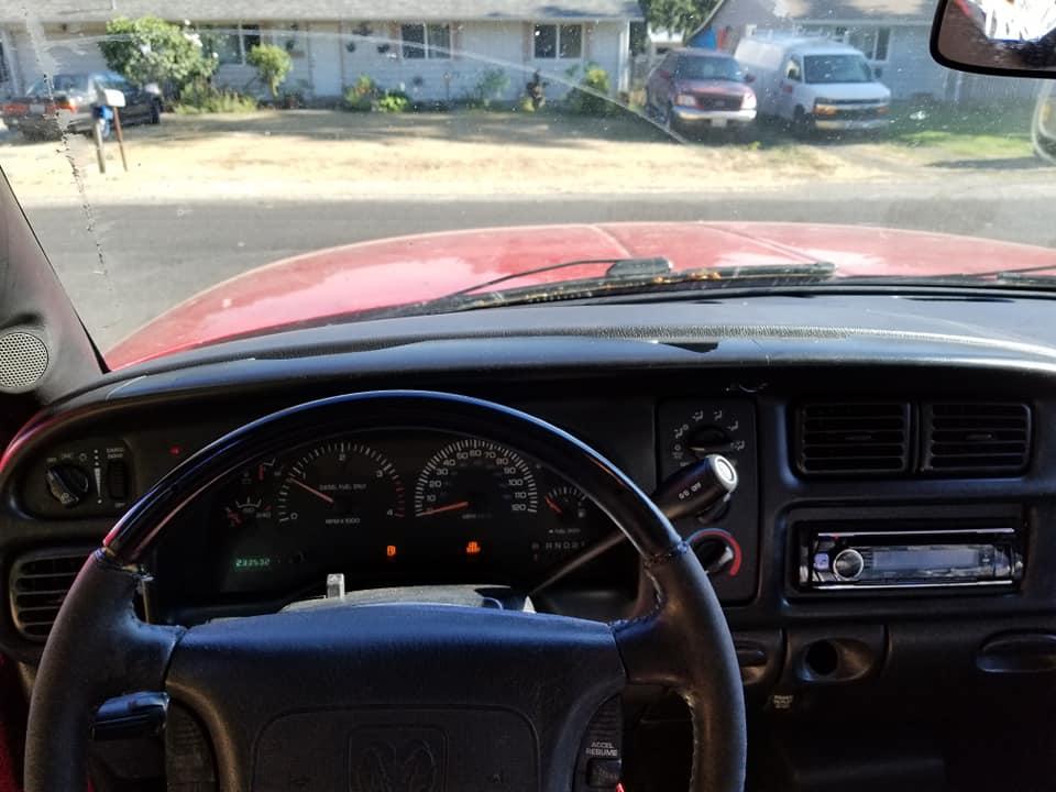
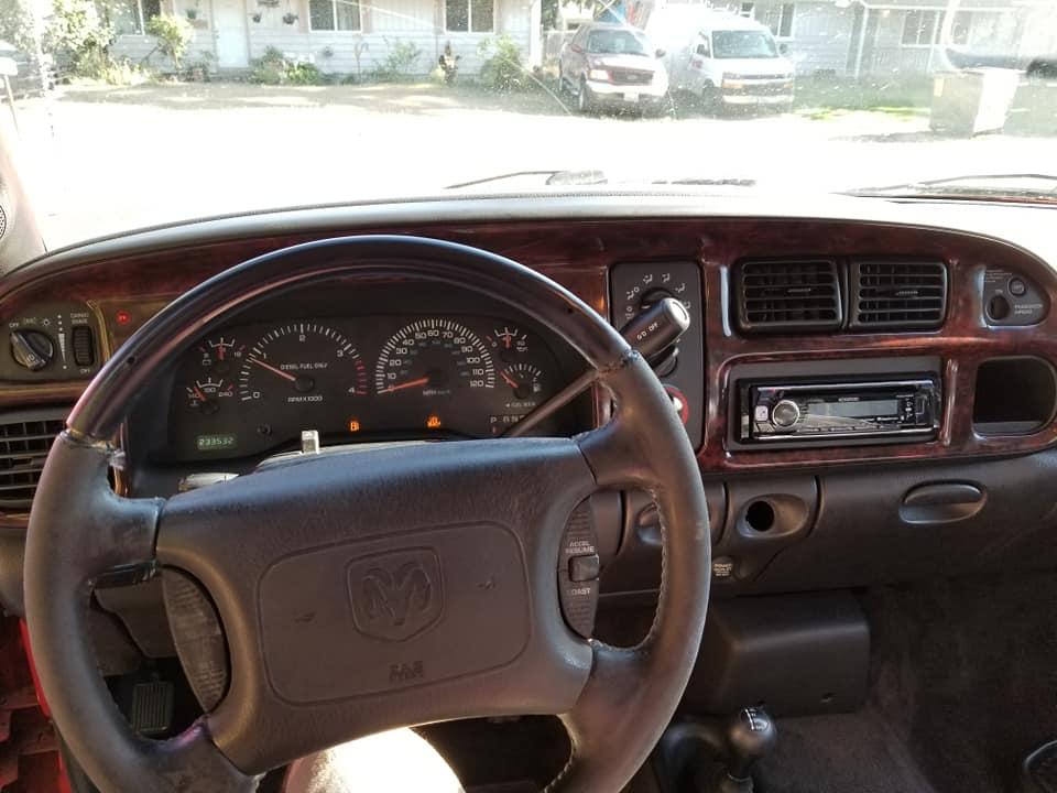
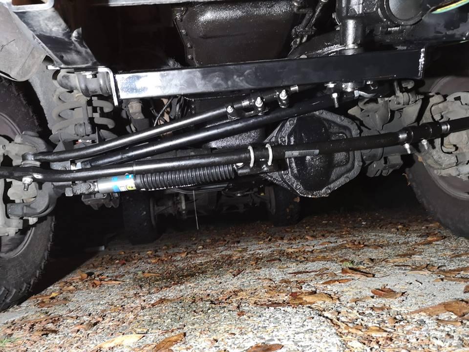

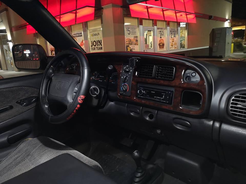 10 pointsThe subject matter has been discussed for years and all diesel enthusiasts/owners know how important it is to maintain proper levels of fuel pressure via the "transfer pump" or Lift Pump for reliable operation. There are many requirements that each owner/operator may wish to achieve in replacing the OE Carter or perhaps making an aftermarket selection. Notably, most have had the rude awakening of a failed VP44 following the failure of the Lift Pump in a too late scenario. The cost of a VP44 compared to the Factory (Carter) Lift Pump is considerable and many of us have learned the hard way. The general consensus among the vast majority is to eliminate the factory OE Carter pump and invest in a robust Class 8 aftermarket system. There are several companies that offer such devices with different performance levels and packaging. Many, come complete with new 1/2" fuel lines, mounting structures, fuel fittings and electrical control harnesses. Some companies offer more modest devices with a budgetary aspect at minimum level. All of this becomes apparent when a conscientious owner/operator begins the research to purchase a new device or system. I for one have stopped reading "Lift Pump" threads because it's so very painful...and I've already seen so many stories of the same old blah blah blah! No, I am not being insensitive to a fellow CTD owner's plight...after all, this is most likely a "new to Diesels" type person. The post is reaching out to the "experienced" diesel enthusiasts for suggestions and perhaps constructive feed-back, prior to making that large investment. Confidence from fellow CTD owners in what they may have purchased or installed goes a long way with the new guy or lady looking for an answer. For just a moment allow me a little latitude...Oh God! Not another Lift Pump story ...Yes but, not what you might think. This will drill-down in a different manor so, please bare with me. The factory OE "Carter" is such a little peanut-whistle why did Dodge do this? The fact is, as many know quite well, the decision was Daimler Chrysler who dictated to Cummins to provide the complete CTD engine package as a drop-in module. Carter's specifications states that, "this pump is to be located within 18 inches of the fuel supply"...it's sad to know these details greatly after the fact. This detail was covered 20 years ago on nearly every diesel website worldwide. This led to the unfortunate degradation of the Carter transfer pumps reputation. In actuality, the Carter LP (lift pump) has excellent design characteristics! At first glance the appearance seems a bit "puny" but, let's look at some of the "not so apparent features"... First of all, Carter is a very large world-wide company who provide a vast selection of produced articles. They also provide excellent technical documentation regarding the application of their products in numerous industrial devices, automotive, marine and aeronautical systems or platforms. Electro-mechanical pumps of this nature, are just a single product that they produce... In our application, CTD's are at first, supplied copious amounts of diesel fuel at acceptable levels to operate the engine and provide flow-through for critical cooling of the VP44 in return to the fuel tank. This is "how" the designed system was to perform. We know as experienced CTD owners that this was not always the case. Many of us know the error of mounting this little well designed pump nearly 10 feet forward of the fuel supply (not to specification of Carter Inc.) and ask this little pump to draw fuel through a small 1/4" line and....force the liquid through "banjo-bolt" fittings as delivery to the VP44? Wow...it's an unreasonable expectation for an electro mechanical pump, that most likely, costs less than $20 to produce in the Philippines. None the less, how many of us have had the occasional chat with a CTD owner (who knows nothing) that tells you they purchased the 2nd Gen new, he has 187K miles and has NEVER replaced the VP44 (he doesn't know what a VP44 is...you just taught him the word) and NO...he has never put a fuel pump into his truck! Yeah ! You know what I'm talking about ! How can this be ? Well...I guess some folks are a lot more lucky than I am... heck...this guy doesn't even know about 2 Stroke for lubricity,... credit our GodFather @Mopar1973Man This photo is well known as a starting point. Also, a depiction of what Cummins had to do to appease Daimler Chrysler's request of a "drop in module" CTD Okay...what is "a well designed pump"... even if it is not mounted correctly? At Carter, where they have been doing this longer than any of our familiar after-market LP suppliers... please note: 1... A fully enclosed hermetically sealed electro-machanical device that allows the liquid fuel to act as a cooling medium and fully immerses the active armature of the 12 volt DC motor to never exceed the temperature of the supplied liquid (diesel fuel)...because it is "airless" (hermetically sealed) there is no ignition to cause flammability. It's liquid cooled ! 2... The entire body or "encapsulation" as hermetic, provides absolute closure or isolation of the motor-brushes as they kiss the surface of the armature in run condition. This is very important as a DC (direct current) motor with carbon pile brushes act as a wild uncontrolled sparking noise source generator !!! This is a normal phenomena of any analog DC brushed motor. A given manufacturer of brushed DC motors, depending on purpose, will take steps to "silence" the electrical (RF noise generation)...the term "purpose" needs clarification... "if the motor is a "CCS" continuous commercial service (runs all the time) then, additional electronic filtering or "shunting" of the armature must be provided. 3... Carter Inc. employs RF Engineers (BSEE graduates minimum) to accomplish technical requirements when contracted specifications are to be adhered to for final product production. An expensive platform in any industrial production would have a string of engineers along with design engineers specking' components or assemblies that will be encapsulated within the finalized product. This occurred in "our" beloved CTD's with electro mechanical LP's....the Carter is "RF quiet" for continuous run condition. Let's examine the electronic terminals of the Carter LP Note: The plastic weather-guard assembly directly attached to the full metal housing that contains the + & - 12 volt DC ! 4... This connection point provides the direct current to power this LP. I wish you to fully understand what you're looking at. As viewed you'll note "both Plus+ and -minus" is provided at this connection point. You must also NOTE, the + and - are arriving directly from a single "pair" connection of both + & - .... I know you'll think I'm stating things "twice" and I want you to know this is an attempt to be a "balanced" feed. The housing of the pump is fully DC grounded when it is attached to the mounting bracket. In a "balanced" feed the "minus" or "negative" is NOT directly at chassis ground...it is merely + and - of the source (12 volts DC in our case) the body of the pump IS directly grounded but, the "source" is isolated from the pump body. Put your Ohm meter on either terminal and touch the pump body....there is NO direct DC continuity in a "balanced" source. This is a sexy way of making things very "quiet" electronically. Professional audio studios are fully balanced systems using "Cannon" connectors with three terminals. One is "plus" Two is "minus" and Three is "shield ground"....hence, balanced and NO Hum or Static noise. (Hey...those guys at Carter make a quiet pump...it's wimpy but, damn quiet) Okay...now let us examine what is going on internally on the back side of the connection point. A careful surgery, with hack-saw in hand, to remove the hermetically sealed body cover and expose the multi-octave filter or "shunting" design of this Carter LP. The double sided epoxy circuit board with modern surface-mount chip capacitors is excellent. This board is located directly at the input of the 12 volt source with virtually zero component lead length (surface mount) to provide shunting of the make and break contact that the brushes are doing directly at the armature when in "run" condition. This DC motor is virtually by-passed or shunted for any RF noise or "spiking" all the way passed 450 MHz! NOTE ! I did say "spiking" or should I say... "ripple"... this is a source of nasty "ripple" directly connected to the entire 12 volt DC rail of our beloved CTD's Quality engineering of analog DC motors remove such garbage before it is introduced to devices such as aircraft, fighter jets, military assault platforms, nuclear submarines and civilian automobiles. There are many preferred after market suppliers of fuel pumps or systems available and many are quite note worthy when it applies to providing solid reliable fuel flow. Many of these platforms exceed the requirements in "fuel flow" for the average diesel enthusiast. Sometimes choices are made because the owner has future plans of building enhanced performance characteristics. Some choose additional GPM for the insurance of added cooling by the "return flow" system design. All of the after market manufacturers of the upper end platforms do this with ease and price the devices accordingly. Caution in selecting any device that may cause unknown after effects in any mobile platform. The CTD 2nd Gen, is something I've looked at carefully for many years and I've made concerted efforts to correct some electrical over sites for the betterment of these noble platforms. I too have made large investments and the after market LP selections are not cheap. I was exceptionally disturbed when I successfully installed an after market LP system. The extreme effort to correctly and cleanly install the system along with all the cool JIC fittings and complete the project with pride that someone may examine my work was all accomplished. Then I shortly discovered the absolute short comings of my nearly $900 investment. I blamed myself for not test operating the device on a test bench and viewing the horrendous RF interference HASH that took out everything from 500 KHz (just below the commercial broadcast band) to well above 500 MHz. Is this important to you?... It is and perhaps it has not become apparent by the way such broadband RF interference manifests itself within a closed stand alone 12 volt system. To make these statements to you, the reader, let me be clear, I use and own a Hewlett Packard 8921A Digital RF test device, at $24,000.00 ...one must be "a fully certifiable crazy idiot" to have this along with a Tektronix 200 MHz 4 channel scope...and someone asked..."Do you need such instruments to look at $25.00 DC motors"...no but, I'm fully confident in my findings. Let's take a look at the much enhanced DC motor of an after market LP...it is irrelevant as to the manufacturer...they are all the same. This is an initial basic disassembly procedure that needs to be performed. It's very easy to accomplish. Once you have the cookie opened you'll be able to view the end-plate where the carbon brushes reside in their respective holders. Many of these devices and earlier models vary by design in physical form but, they are all the same in regard to an end-plate with brush tube holders. Here is the end-plate removed from a different LP unit and we can see the very minimal by-pass engineering of a single .47 Mfd mylar capacitor directly across the two brushes. Note, the lead length. This is typical of an inexpensive analog DC motor...I'll estimate the average wholesale cost of this to be somewhere around $10 to $15 US dollars. It would vary greatly, according to quantity buying levels. The only capacitor seen here is barley a by-pass or shunt...I'd prefer to call this a carbon brush protector. As the armature spins in normal operation, the "make" and "break" of the brushes riding against the armature where "flame" occurs...this cap is merely removing or dampening the "spark" and aiding brush-life longevity. At .47 Mfd it's really only helping at the lowest frequencies to roll off the RF spiking, also with long leads, transversing the distance between the two brushes does not help with the higher frequencies of this wild free-running spark-gap transmitter. This is a far cry from the excellent by-passing techniques incorporated into the wimpy little Carter device. Let us take a look at the fix procedure to begin " RF silencing" one of these very substantial LP platforms. We can't be as effective as the fully closed hermetically sealed package but, with careful effort you can knock this "ripple hash" down by 40db or better in just this simple step. The procedure above depicts a simple "drill and tap" technique using small machine thread hardware. 6/32 or 10/32 should suffice. You can use what ever hardware is available in your junk box as long as it is small enough to fit into the limited working space. Purchasing a small tap and companion drill at your local hardware store to match your "screw-thread pitch" is very low in cost. The skill required to do this is modest, just take your time and carefully hand-cut your threads gently. The cast aluminum end-caps are very easy to drill and tap. NO 9% IPA's should be consumed prior to drilling! Keep your hole straight and pay attention to the "depth" of your drill. With the armature removed you can "eye-in" an approximate location for the mounting hole to accommodate the miniature "lug"...this is where you make an accurate decision of the "angle" for the lug's contact arm to avoid contact with a spinning armature in "run-mode". You must also consider component "lead length"...keep this EXTREMELY short...it will be like working on a Swiss watch in confined space. NOTE: You must loctite your threads! This procedure is introducing component count within a very critical area...errors in loose components will be catastrophic !!! You will make NO errors here! Sorry...my photo is fuzzy. The photo below is zoomed-out for examination of component placement within the end-cap structure. It is tight but, it is precise and highly efficient. This depicts component selection: two each .1 Mfd silver Mica 100 volt dipped packages. I happened to have these in my junk box and standard miniature ceramic caps would also suffice. This completes the "critical" internal modification to initially "RF silence" the armature brush contact event point. I buy electronic components/parts from DigiKey or Mouser...these two capacitors will set you back about 30 cents each...your shipping cost will be ten bucks! Boy...I miss those cheesy little Radio Shacks. It was so convenient to buy little things like this for little money within my own community. Times have certainly changed. Now, carefully reassemble your enhanced LP device and mount it into it's operational nest on the vehicle. The photo below is the final step in this procedure. Again, this shunt capacitor is a .1 Mfd Orange drop package rated at 100 volts. I do prefer this package over standard Ceramic disks under the hood within engine compartments due to heat stress. These maintain tolerance over an extremely wide temperature range. The shortest leads possible, again, is the goal...the lead is directly connected to the relay socket where the 12 volts DC is connected through the relay contacts, that when "closed", provides DC excitation to the LP. I could have made these leads shorter but, I utilized the present ground on the firewall for convenience. Insert the relay back into the socket. This now completes the entire procedure. The monetary expenditure amounts to less than $1.00 for the capacitors. The time involved is substantial. The $689.00 plus dollar, advanced LP platforms available should have arrived fully prepared for trouble free installation and operation. The design engineering staff at Dailmer Chrysler would have never introduced an uncontrolled CCS constant run DC motor device into their platforms at any level. Cummins also, would have never allowed a DC pump without qualification standards to be specified for any production platform. The factory OE Lift Pump from Carter is a very under powered volumetric unit and their is no debating that short coming however: electronically it's design is superior in every aspect. The entire hermetically sealed housing acts as a complete Faraday Shield to fully encapsulate all electromagnetic static fields of force. It is a "dead silent" RF void device! This is just an example...all of the after market companies tout their prowess in delivering liquid fuel at astounding levels of performance, be it a stock engine or perhaps an extremely high horse powered competition street killing monster. None of them provide a civilized RF silenced DC motor to prevent "other" electronic automotive control elements from being harmed when operated within the confined structure of the vehicle. Note: not one bit of verbiage regarding the actual DC motor that powers the device! But, it pumps fluid like heck! I so dearly appreciate the flow factors, the filter systems, the mounting structures and comprehensive packages to alleviate all the short comings of my dismal factory transfer pump issues. Knowing well, that I'll never allow my one thousand dollar plus VP44 from ever being fuel starved again, by selecting an aftermarket LP system...only to realize afterwards, that the introduction of this major investment into my vehicle is now causing electronic issues, else where, within the vehicle! The expensive sound systems, vehicle speed sensing systems, erratic operation of TC lock-unlock, cruse control abnormalities, and radio communications equipment. All of these things at one time operated without error, you enjoyed the accurate trouble free aspects of your prized motor vehicle, then...something happened! Being cautious about adding any electronic implement into a trusted vehicle is always prudent. Asking the right questions before hand is always best practice. This information applies to ALL Vehicles regardless of manufacturer Ford, Chevy or Dodge. This article is following additional postings on this web-site...Mike Nelson @Mopar1973Man and Nick @Me78569are struggling to keep this small and independent site operational. I am not affiliated with any supplier or manufacturer...I am a contributing customer who appreciates the time proven and solid information/guidance these two men provide to the diesel community. I humbly share this knowledge with the CTD fraternity with enthusiasm, for the improvement of our platforms...may I ask a very small favor...if you find the information on this site of value could you please consider making a one dollar donation to the site to keep the lights on Thank you, Respectfully, W-T10 points10 pointsI try to be proactive towards the maintenance of my truck rather than reactive..... Knowing that the OEM Bosch alternator had almost 120k miles on it, I felt that not only was it probably going to give me DC troubles in the near future but I was also sure that I was most likely experiencing some AC issues as well, especially during the cold morning and hot summer weather. Why I say that....? I've tested my AC voltage before during the summer and it was within "spec", but still I thought the readings were higher than I'd like. So I recently tested again before installing the Nations unit just to confirm and what I got was about .044 during idle. Yes thats acceptable but also understanding that its 35* outside and the engines warm enough that the grids are not cycling, I felt that there was nowhere for the AC readings to go but up. Meaning, as the weather gets warmer and/or the alternator is powering more accessories, the AC voltage reading will only increase. Alternators will produce the least amount of AC at idle with little to no electronics running. But ramp the throttle up to around 2000 - 2500 RPM, turning on every electrical component and the readings will always increase as the diodes work at converting. I saw that the last time I tested it in the summer so I felt I'm justified in replacing before problems arise. Plus I noticed a considerable amount of red brush dust on the tensioner pulley (seen in the picture) which reassured me that it was getting old. So I've decided to replace it. Exploring my options, they are as usual..... To either rebuild my current one, get an over the counter "lifetime warranty" parts store unit and hope for the best, or look for one of the few high dollar units available out there in the aftermarket world. Well given money is always a variable, I chose to go with the Nations unit I've heard good things about. Not only are they priced what I consider to be reasonable for what you get but they're also American made. Plus if I have trouble, I'd rather deal with Nations than deal with either Autozone, NAPA, O'Reilly, etc... and risk delicate electronics on this truck. Yes, I could have had it rebuilt but I'd still have an alternator that may or may not generate more AC than I'd like because of the windings and diode count, but I'm sure I'd probably have battle with the small shop explaining what I want and why, since most places are more concerned with DC output rather than what the AC voltage readings are. This is the one I opted for. 180 amp, hairpin wound, 12 diodes, and uses the stock pulled size. http://www.nationsstarteralternator.com/180-Amp-HP-High-Output-Alternator-for-2000-Dodge-p/13874-180-hp.htm Just to be clear.....what I was experiencing with the OEM alternator was the norm and had been this way for years. That said, typically the volt gauge in the cold mornings would do as described: Turn key ON, gauge drops to the lower portion of the "normal" range. Start engine when WTS light turns off. Gauge immediately drops back down to the lower portion of normal as the grid cycles on again. Gauge starts to climb rapidly as the grid cycles off. Seconds later the grid cycles on again and the gauge dips down to the lower portion of normal. This back and forth takes places for a few minutes depending on the ambient temperature. And when it does, the engine clearly lets me know that the grids are cycling by either making the tell-tale noise of loading down from the alternator drag, and/or I can get a slight momentary idle lope only to immediately regain regular idle. The lights dim considerably as well and the volt gauge generally reaches just a tick over 14 volts when its completed the event or I drive off. Well after the install of the Nations unit this is what takes place: Turn key ON, gauge drops to the lower portion of the "normal" range. Start engine when WTS light turns off. Gauge does NOT drop back down to the lower portion of normal as the grid cycles on again, but rather remains up around 14 volts. Gauge moves a tad higher than 14 volts as the grid cycles off. Seconds later the grid cycles on again and the gauge drops no lower than 14 volts. As before, this back and forth takes places for a few minutes depending on the ambient temperature. But this time the engine does NOT react the same but rather hardly lets me know that the grids are cycling. There is no tell-tale noise of loading down from the alternator drag and I seemingly had no slight momentary lope during that moment either. I cant say about the lighting at this point because I havent driven it during the night since the new alternator was installed. But I'm going to guess that they will not dim nearly as much given that the alternator appears to be cranking out more amperage during idle while creating less load on the engine. I also tested the AC voltage as soon as I installed the Nations unit, while during the same cold weather, and saw about .020. I'll be testing it some more as the weather warms too. Lastly, I would say that of the few times I've driven it since the install the engine has slightly better manners during the cold weather. This only further supports the understanding that these trucks are VERY susceptible to electronic anomalies and the alternators are absolutely something to pay attention to.10 points10 pointsA lot of good info here... I, personally, consider anywhere from about 150-180 degrees F to be an ideal operating temperature for an automatic transmission. Many run cooler than this, which is really no problem. Some run hotter than this, which is not a big problem (to a point, obviously), as long as the cooling system is able to bring it back down when the "heat-inducing" conditions are removed. When you're working the transmission, it's going to make heat. There's no getting around it. As long as that heat can be managed, life is good... I am a big proponent of leaving the OEM heat exchanger in place. It is technically called the "torque converter cooler" by Chrysler, and that's exactly what it is. When you're working your converter hard, the fluid temps coming out of it can be downright scary! The heat exchanger does a fantastic job of knocking that temp down to where the air-to-fluid cooler (auxiliary cooler) can manage it effectively. Does the heat exchanger heat cool fluid? Yeah, some... But not enough to worry about, and the benefits when the fluid is hotter than the coolant cannot be overstated. I highly recommend placing the temperature sender in the pan, as many have mentioned. The Low/Reverse servo pressure tap is where it ends up a lot of times, but there's not really any fluid circulating there. It just kind of gives you a reading of the temperature of the case right there. Better than nothing, yes, but not ideal. Plus, if you put a billet servo piston in the Low/Reverse, the sender will interfere with its operation. I have found, through a bunch of recent 3rd Gen testing recently, that the OEM temp sensor in the transducer seems to read high...sometimes by quite a bit. If you have a scanner or monitor that is simply pulling transmission temp information off of the data stream, I would verify its accuracy before I got too worked up about anything. A recent customer was concerned about his 190-200 degree indicated operating temperature (Edge CTS2). Testing this info against a known good gauge (and also an infrared heat gun) showed that it was reading about 25-30 degrees high. A new transducer brought things much more in line, but it still read high. Take it with a grain of salt until you verify its accuracy. Running a deep pan is never a bad idea, although don't look to it to solve an overheating issue. More fluid is a bigger heat sink, and does tend to lower operating temperatures with all other conditions being equal. But it you have a heat issue, more fluid will have a small effect on things. The main reason that I like to run an aftermarket pan is to strengthen the case, as @jlbayes mentioned. The bottom of the case on a 46/47/48 RE transmission is wide open, and case flex can be a pretty big deal when the torque numbers reach the stratosphere. A good aluminum pan really helps...probably more than you would think. There are many good pans on the market. I have used Goerend, Mag-Hytek, LPW, B&M, and probably others as well. All are good quality pieces, and do their job well. I will say that I have never been very impressed with Derale pans. No offense to those who have them, but they are really quite flimsy when compared to an OEM pan, and offer no additional case rigidity, as was mentioned. I have been through some ugly wars with Derale pans trying keep them from leaking as well.10 points10 pointsThank you,,,,I'm moving right along. God helped the snail reach the ark so we are moving right along at the pace HE has determined for me, I also give new meaning to our Mopar t-shirts, Achieve your destination!!!!Life has so very many surprises.,,,setbacks too,,,but these are our challenges. I'M GOING FOR IT!10 points10 pointsSitting at home waiting on the insurance adjuster. I'm glad she's home safe!!10 points10 pointsDont worry guys..... I understand some of our well minded leaders have it all figured out. Apparently college tuition will be free and society's problems will be fixed. Smart phones are government paid. No one will have to perform any tedious manual labor any more and everyone will be making triple digits with huge retirement pensions, and bonus.....all medical will be free too boot. We'll be able to use in any bathroom we choose, wear anything that fits (if you feel like wearing clothes). We can have sex with anyone and anything we desire, and marry everything including inanimate objects and fictitious beings. There will no longer be issues with high priced fuels as municipal transportation systems will readily take us wherever we need to be in electric buses or bullet trains pointed in every destination. Drugs will never be a problem again as all of them will be legal and you'll be able to get them and do them at your leisure. The police system will no longer be needed since no longer breaking the law is a problem as everything is now OK. Guns?.....who needs guns in a place like this because our world will be a FREAKING UTOPIA!!!!! And yeah, EVERYONE is welcome too. Not sure where all the money will come from and I'm not sure about much of the details, but dont bother asking questions..........because thats not the point.10 points10 pointsYou basically have two different pressures at work in the VB when determining upshift and downshift points. First, there is governor pressure, which is determined by road speed. Early transmissions (46RH, 47RH) used a mechanical governor on the output shaft, and the newer RE transmissions replaced the mechanical governor with the governor pressure solenoid/transducer setup that we all know and love. The PCM generates the governor pressure electrically via the solenoid, and monitors the governor pressure via the transducer. Either way, the faster you are driving, the more governor pressure... Second, you have throttle valve, or TV pressure. This pressure is determined by throttle position. When you press on the throttle, the TV cable pulls on the lever at the transmission, which rotates the TV lever shaft, which then presses on the end of the TV plunger in the VB. The plunger then loads the TV pressure regulator spring more heavily which, in turn, increases TV pressure; the more throttle, the more TV pressure... There are two shift valves in the VB that use governor and TV pressure to determine shift points; the 1-2, and the 2-3 shift valves. (The 3-4 shift valve and TCC lockup valve are controlled separately by the PCM via solenoids and do not use governor or TV pressure to determine their shift points.) At each shift valve, governor pressure acts on one end of the valve, constantly trying to stroke the valve to the "upshifted" position. At the other end, there is a spring holding the valve in the "downshifted" position. In addition to the spring, TV pressure also acts on that same end of the valve, assisting the spring in holding the valve in the "downshifted" position. When you are at a standstill, governor pressure is at a minimum (basically zero psi) and the shift springs hold their valves in the "downshifted" position - first gear. As you take off from a stop, governor pressure begins to rise, acting on the end of the shift valves. If you are light on the throttle, TV pressure is very low and governor pressure quickly rises to the point that the force of the 1-2 shift spring at the other end of the valve is overcome and the 1-2 shift valve strokes, commanding a 1-2 upshift. The transmission is now in 2nd gear... If you are heavier into the throttle, TV pressure assists the spring with greater force, making it necessary for governor pressure to build to a higher level before the force of the spring AND the hydraulic force of the TV pressure acting on the end of the valve to be overcome. This is how the transmission holds each gear for longer when you are heavier into the throttle. As you continue to accelerate, governor pressure continues to rise until the 2-3 spring force (and whatever level of TV pressure that is acting on the 2-3 shift valve) is overcome and the 2-3 shift valve strokes, commanding a 2-3 upshift - 3rd gear... When commanding a downshift, you press on the throttle harder and TV pressure rises. When TV pressure rises to the point that (with the spring's help) governor pressure can be overcome, the valve will stroke back to the "downshifted" position and either a 3-2 or 2-1 downshift is commanded, depending upon which gear you were in. If the throttle application is abrupt enough, and TV pressure rises quickly enough, both valves will be stroked to the "downshifted" position nearly simultaneously, and a 3-1 downshift will occur. This is kind of a simplified explanation of what goes on in the Dodge valve body for 1st - 3rd gear. As I stated earlier, 4th gear (OverDrive) and TCC are controlled directly by the PCM via their respective solenoids.10 points10 pointsI did some more measuring and testing for the MPG crowd. Before I start I will say that I just verified my SGII and its right close to being on the money (off by 0.2 gallons). I'll assume that a slight error between the ScanGauge and the fuel pump. Now I my truck conditions are Edge set for 5x3, IAT fooled to 143*F, Engine coolant varied from 188*F to 197*F, winter fronts still on. Actual weather was high of 65*F (actual IAT was ~90-105*F) Now since I was on I-84 down in southern Idaho today I figure I open the beast up and let it fly low for once. So I set the cruise for 75 MPH and reset the current MPG counter and measure for about 20 miles of highway. I was pulling roughly ~13 MPG. Then after shopping in Nampa, ID and got back on the same stretch of highway again and set my cruise this time for 65 MPH then reset the ScanGauge II again and measured about 20 miles of highway again. I turned out ~18 MPG. Then even with all the playing driving fast and slower I still pulled in the yard with a total of 22 MPG. So from this rough measurement I found that roughly for every 10 MPH above 55 MPH I lose roughly 5 MPG. This is calculated numbers here. According to Google Maps its 300 miles round trip what I drove. Time to travel distance 300 miles / 55 MPH = 5.4 Hours 300 miles / 65 MPH = 4.6 Hours (0.8 hours less than 55 MPH) 300 miles / 75 MPH = 4.0 Hours (0.6 hours less than 65 MPH, 1.4 Hours less than 55 MPH) Amount of fuel consumed 300 miles / 21 MPG = 14.2 Gallons (@ 55 MPH - not a true 55 MPH because of testing) 300 miles / 18 MPG = 16.6 Gallons (@ 65 MPH) 300 miles / 13 MPG = 23.0 Gallons (@ 75 MPH) Cost difference @ $4.019 Gallon (which I paied for) 14.2 Gallons x $4.019 = $57.06 16.6 Gallons x $4.019 = $66.71 ($9.65 more than 55 MPH) 23.0 Gallons x $4.019 = $92.43 ($25.72 more that 65 MPH, $35.41 more than 55 MPH) Another tidbit. I get the same MPG's towing my RV at 55 MPH than I do driving empty at 75 MPH. Also the fuel consumption rate at 75 MPH is just about the same as climibng a 5% to 6% grade at 55 MPH. This shows that amount of rolling resistance and wind drag differences between 55 and 75 MPH.10 points10 points[TABLE=class: page, width: 100%, align: center] [TR] [TD][TABLE=class: tborder, width: 100%, align: center] [TR] [TD=class: alt1, bgcolor: #F5F5FF]I thought I would throw out my experience with the setup and the company. I ordered an Assassin Pump from DTT several months ago and I knew it would take me a little while to receive as DTT informed me of a few changes taking place with the pump. All the same I was extremely anxious to get my hands on the pump. Being a common logic/mechanical thinker I felt the mechanical pump would be a great addition to my system for its simplicity and performance capabilities. I received my pump and I was immediately impressed with the build quality of the pump itself. Nothing on this pump feels cheap, there is no free play in the tolerances of the pump gears, shaft. Really the only parts to potentially go bad are the two small shaft seals, which I believe could be locally sourced and replaced very easily. Did I mention the pump is anodized blue and is very appealing to look at even though no one really ever sees it, you will enjoy putting it on and looking at it. On to the good stuff. As previously stated, I am a mechanical person, and I pretty much do everything to my rig on my own. This was no different. I ordered a complete kit as I don't have the time to source all the fittings and hose to do the job. I was placed on hold for a couple days as there was a fitting that I did not receive, however a quick phone call had one on the way immediately and I thank DTT for the prompt response to service. My actual total time of install was about 4-5 hours. I didnt work feverishly to complete the task as it was my first fuel system install and I wanted to understand the system and do it properly. I began by mocking up the pump onto the oil pan. For those that would be concerned about knocking this pump off, forget about it, I would almost guarantee a higher chance of knocking off an airdog or fass than this. Especially in my case as I have a PSC steering brace on my truck, making it dang near impossible to hit the pump. The pump is simple to mount, and simple to adjust for belt deflection. Its a two piece mount system, with the pump being able to slide a small amount of distance to determine tension. The belt requires very little tension due in part to the massive cross lug design of the belt and pulleys. I carry a secondary belt in my truck but so far the current belt shows no signs of wear or slipping. The installation of all the hose is kinda your own creation as you can choose what direction you wish to run it within the engine bay. The fittings all seem to be of high quality. All the same I used a permatex thread sealant that is not susceptible to deterioration due to contact with fuel. The worst part of the install is dropping the tank to install the draw straw system. The draw straw I received is the one from Vulcan installing back within the tank module. Pretty simple and very effective. I have been down to just below a quarter tank and haven't had any issues with running out of fuel, and I shouldn't as the straw is the exact same length as the factory straw setup. The pieces for the module are nice cut pieces that fit well. Providing a larger 3/8 return line back to the tank in addition to the line already returning from the VP overflow. Simple and effective setup. Once I got it all installed, I prepared to fire up the truck. I removed the inlet pump hose, pressurized the tank and in a half second I was loosing gold out the inlet hose. Connected the inlet hose, removed the pump from the mount. (2 bolts), and cracked the lined at the filter housing. I placed a drill on the shaft and cranked it up, and again, fuel was almost immediately expelling from the line. Buttoned up the lines. I cranked the truck for about 15-17 seconds and she fired right up. I immediately checked for leaks, I had one at the TEE but only took a brief second to lock down. No more leaks from anywhere else and so far none there after. I then began to check for proper pressures. At idle, the pump is pushing out 12-14 psi depending on cold or hot fuel. Upon touching the skinny pedal, PSI jumps to 19-20 instantly. Under WOT, pressure hangs tight at 20-21psi. So far I haven't had any issues with it maintaining pressure. My truck starts faster with this setup than it did with the factory pump. After I replaced my VP a month or so ago I had been having an occasional long crank session. Since the assassin install I haven't had a single start longer than 1 second. I really like the fact that the pump increases pressure under throttle rather than losing pressure. I have not had any experience with the airdog, fass or raptor, but I know they lose rather than gain. The other thing I like is that even at idle, just blipping the throttle pushes it well above the needed 14 psi to cool the VP. During the winter, while the truck is high idling, it will also be above 14 psi, with no issues. I like the fact that there are no fuses to blow, its highly unlikely the gears are going to self destruct, and the belt can be replaced with only one wrench. I intend to purchase a CAT filter kit from Vulcan here soon and install it, eliminating the stock housing kit, even though I haven't had any issues, I want to protect the pump from debris also, so I will pre-filter the fuel with the CAT system, (and its just plain better filtration). I just thought I would share my experience with this pump and invite anyone looking to replace or upgrade their fuel system to give this pump a try. Any and all questions I had were promptly answered by DTT(Stefan). All in all I couldn't be happier with my purchase and the performance it has delivered. [/TD] [/TR] [/TABLE] [/TD] [/TR] [/TABLE]10 points10 pointsHere is some data I have collected over the last 18+ months. All of it is directly from the mfgr.10 pointsBetter Headlights for your 2nd Gen Dodge Ram Truck Parts Needed:: Morimoto Projector Kit ( ensure you get the 9004 kit with the High beam controller AKA Motocontrol and the longer thread reflector) Clear lense housings ( not required, but way better output, ensure housings are aimable.) Flat head Screw driver Phillips Screw Driver T15 torx screw driver 10mm socket extension / 10mm open ended wrench Oven Epoxy Why to upgrade to Bi-xenon Projectors It's no secret that 2nd Gen Dodge Ram Headligts are terrible from the factory. There are various things you can do to help, Britebox relay system, bulbs, sport conversion, and my least favorite.....HID's, or a Projector retrofit like this. While the retrofit is the most costly I believe that it is the best choice. No tonly do you get to upgrade to xenon bulbs, but you upgrade to projectors that were designed for the xenon bulb, which is key. I truly hate seeing guys throwing HID's into their halogen AKA oem housings and claiming that output is great for only $50. What they don't relize is that when you throw a differently configured bulb into a halogen housing you are going to scatter light. The key to not scattering light, AKA blinding oncoming traffic is ensuring that the reflector housing is engineered for the bulb that is in it. The distance of the filmate is key when it comes to how light reflects in the housing. As you can see here moving the filmate, or installing a different type of bulb throws everything off. This is why I always prefer that if you are going to run different lights that you ensure the housing is right for the bulb. since the Morimoto projectors are bulb for a xenon mini h1 bulb you don't have to worry about it. You can have your cake and eat it too. The Design of the Morimoto Mini H1 Projector headlights You can see from the above that the Shield, or Cutoff Plate ensures that the light is reflected and projected in a manner than doesn't blind people. The result of a sheild in the up position does this You can clearly see the cutoff and how it prevents oncoming traffic from being blinded. Here is a closer look at the Cutoff Shield To activate you High Beams the shield is pulled down allowing light to be projected without being cutoff. The result is Ok that is enough on why I choose the Morimoto Mini H1 Bixenon projectors as the new headlights for my 2nd Gen Dodge Ram. Break Down of the Projectors This is most of the hardware you will get with your kit. The nice thing about the Morimoto kit is it allows you to install the projectors into the OEM bulb socket. This allows you to retain the OEM aiming ablility. the only hole you will need to drill is for the High Beam wiring. Sport Housings I decided to jump to sport lights in the middle of this process. These are the lights I got from Ebay. I am VERY happy with them. Amazon Sport Headlight Housings Link PN: 55077025ac 55077025AG They required a little cutting to get the projectors set in them, but nothing bad. You can get extended threads projectors so I would suggest that. Removing your housings to remove your Stock 2nd Gen Dodge Ram Headlights you will need a 10mm socket and an extension. There are 3 bolts holding the light in. Remove the 3 10mm bolts holding the light in (Red dots in picture). The lower inner bolt is somewhat hard to get to. I found that going from under the truck was easiest. Next pull the light straight back to pull it out of the push fittings. You should feel it "pop" out 3 or 4 inches. Next remove your blinker bulbs and disconnect the headlight bulb. Next remove the housing by sliding them towards the outside of the truck, twisting somwhat to free the housing. Take your time as this can be a stubborn part to get out. once you have both housings out you can go inside. Removing the headlight lens The easiest way I know of to get the lens off the housing is to use the oven. I set my ovens temp to 170*f and put the housings in for 30 minutes or so to heat the glue and make the lens easy to remove. Ensure you keep and eye on the housing while it is in the over. I have seen some ovens that are not accurate on heat and ended up melting the housing. Once your housings are to temp remove them and carefully use a flathead screw driver to pry the lens open. Move slowly around the lense and pry the lens off. you should feel it release, don't pry hard, if the glue isn't letting go put it back in the oven for another 10 minutes, increase temp if needed. Your end result should be like this It is key to notice that if you are using the OEM lenses that your output will be less than wonderful. you can see in the image above the Fluted design to help scatter the halogen bulb output. This however makes the cutoff line fuzzy. This is why a clear lens is worth having. Installing the Projector Remove all of your hardware from the projector so there is nothing on it. The threaded section should fit into the OEM bulb hole. Insert the projector into the housing from the front. Turn the housing over and insert the rubber washer, then the alighment washer, then the locknut. Tighten the lock nut down somewhat snug. Don't over tighten as you will have to level the projector by rotating the projector in the housing until the output is level. The housing back should look like this The Front will look like this Note the Red Dot. you will need to drill a small hole here to run the high beam wires though. Once you have your projector in the housing, install the Bulb holder onto the back of the projector, there are threaded holes for the small phillips screws. Install the bulb then the retaining clip. Installing the wiring The Morimoto Wiring Harness only requires connection to one of the 2 oem plugs. The wiring harness looks like this you need to make connection to the Battery + then a body ground on the end of each Ballast Output. The Input from the car plug will be a female socket 9004 connection. I choose to install the bulk of the harness on the Passengers side since I have more space over there. This system already draws power right form the battery so there is no need for a Bright Box type relay system. You will need mount the ballast's one on each side near the back of the light. I choose to the left and right of the radiator right above the light. Plug your ballast into the "Ballast output" plug from the harness. Leveling / Tuning your lights after everything is reinstalled into the housings you will need to put them into the truck and level the projectors. This needs to be done before you put the lense back on. Connect the bulbs to the wiring in the truck. Install the housings and install the bolts to ensure that hte housing is tight and won't move. You will need a large flat surface and level ground to do this. Park 20ish yards away from the wall on flat ground, turn the lights on. The truck will need to be running to trip the ballasts and ignite the bulbs. Once the bulbs are on you can kill the truck. Look at the output of the light once side at a time and level the cutoff line by rotating the projector in the housing slowly until you are happy with the level of the light You can see in this picture that the projector needs to be rotated slight clockwise. Once you are happy with the level of the cutoff remove the housing and tighten the locknut down. Be careful not to move the housing or projector. Repeat the process for both lights. Remember you are not aiming hte lights, only leveling the cutoff line. Ensure that the hole you drilled for the high beams is sealed with RTV or epoxy. Reinstall the lense Once you are happy with both sides use some epoxy to reattach the lenses to the housing. Ensure that it is a tight seal. Allow time for the epoxy to setup. Reinstalling housings and aiming headlights Reinstall the housings and install all bolts ensuring that the lights are held tight. Connect all lights and wiring to the housings. Now you will need ot aim your new lights. You will need the T20 torx to aim the lights. Park 25ish yards away from the large flat wall on level ground. Typical rule of thumb is you want your light hot spots to be directly in front of the bulb. Easiest way to ensure this is done is to pull close to the wall, aim the lights left and right until it is right in front of the bulb, then slowly reverse ensure that the hotspot does not move left or night as you backup. If the hotspot moves left or right adjust the housings to counter act this. Next you need to aim your lights up / down. Again rule of thumb is you want your hotspot at 25 yards to be 1- 4" lower than the level of your headlights. IE pointed down slightly. This will take some adjusthing. The cutoff lenses will keep you from needing to point your lights down very much. Depending on the height of your truck you might be able to get away with 1" of drop at 25 yards. The higher your truck is lifted the move drop your lights will need to keep from blinding people. This might take some trial and error. Drive around some, if peolle flash you drop your lights some until you are no longer flashed. In the end you should end up with lights that are much better than OEM. Your cutoff's should be straight and you should have a VERY wide beam. the ground is not level but you get the idea. this article should work for all 2nd gen Dodge Ram trucks 1994 , 1995, 1996, 1997, 1998, 1999. 2000, 2001, 2002.9 pointsAs of last night I've started my own shop in Pollock Idaho. I've been taking to people about the lack mechanic shops in the area. Then a guy I've know that has a 3 bay shop already he's will to make a business agreement where I get to use his shop for a percentage of the profits. So far this is a work in progress and nothing is set in gold yet but working towards how we both would like to see things happen. I will have one bay with a 8,000 pound two post lift and then two other flat ground bays to work from. Floors are heated in the winter time, and A/C (swap cooler) during the summer. I've got to give the owner a hand moving some stuff to storage but he's agreed to clean up his junk and get me working space.
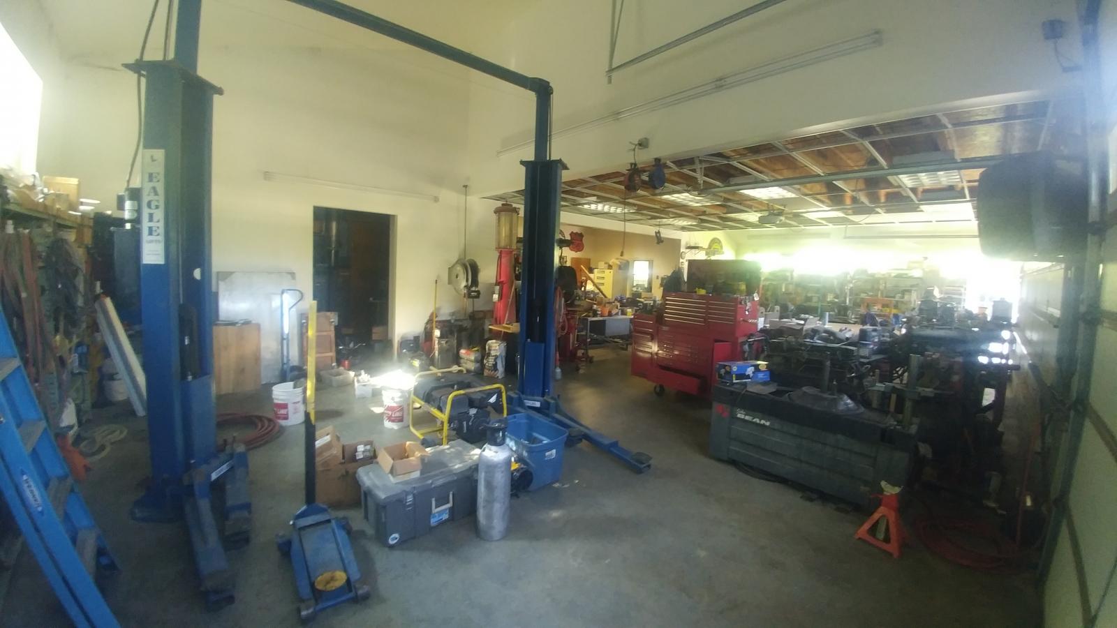 9 points9 pointsAfter getting rear ended by a loser with a suspended license and no insurance I decided it was time for a real rear bumper. I really didn't want to spend $700-1500 for a bumper so I started building my own. It's all 1/4" plate with 1/2" brackets. I got all the metal from Metal Supermarket from their cut table for 0.75 per pound. I still have to cut holes for the back-up lights, weld the bumper to the mounts, and either paint or powder coat it. When this one is finished I will be moving on to the front bumper. I plan to build it in the same style and have a winch mount. If anyone has done something similar i welcome any input, criticism, or advice. This is my first bumper build but I'm pretty happy with the way it is going. Ill post more photos after its comple.
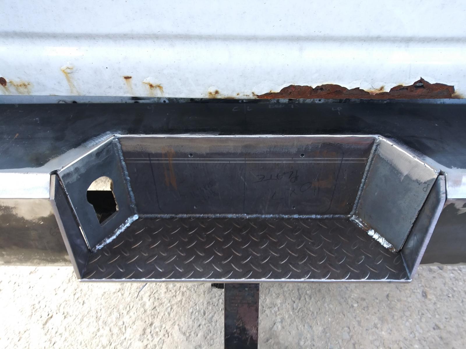
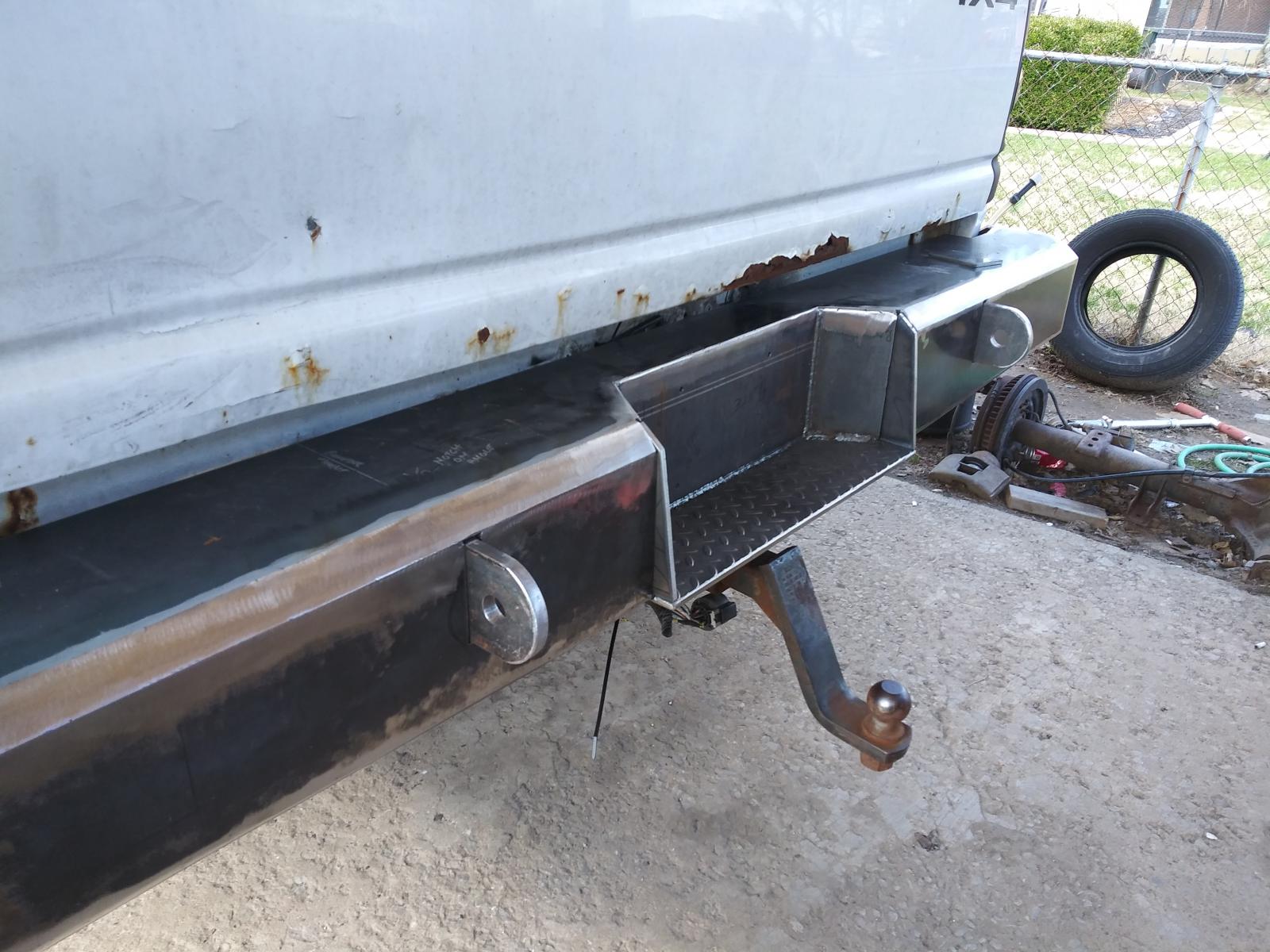 9 points9 pointsI would like to say thank you to all of you for the prayers. As for this morning, a wonderful gent started talking to both MoparMom and I. The conversation continued and I finally gave up and told them what is happening to both of us. Being MoparMom on dialysis and me with bladder cancer. He admitted that he is not a priest but asked if he could pray for both of us. I said "yes". We all gathered in a circle in the restaurant and he proceeded to prayer for both us on the spot. Then conversation continued after the prayers and then he took our bill and paid it. Wow! What an awesome morning from a total stranger.9 points9 points(With a Mad Scientist voice) It's alive! It runs once again! I'm quite amazed. I got it started and left it idle while I picked up a few things then kicked it out the door to warm up more as I clean up a bit more stuff. Then I took off down the road riding easy on it till it warmed up and the thermostat opened and cycled once. I knew it needed to burp once. After that, I gave it a few good stabs at the throttle and it pulls like a scalded ape. Nothing long but something to create EGT's a bit. After about 5 miles I stopped and check for leaks or any issues. None to be found. Continued down canyon for another 5 miles. Pulled off again checking for any leaks or any issues. Still nothing. Cruise on back home and sun is just going down and with my flashlight, I caught a glance at my breather pipe the blow by is greatly reduced. The vapor comes out the end of the pipe like steam off a hot cup of coffee in the morning. I'm leaving the beast outside to chill tonight so I can see the start up and what the smoke if any.9 points9 pointsWell first off I've got to Thank a forum member... But first the story... After going back and forth with it not going to be ready today to being ready at 3:30pm. I finally got ahold of MoparMom and told her we'll be going after the head when she is done with dialysis treatment. After an one hour drive to the shop. I'm greeted by Justin telling me... "Whatever your doing and the friends you have you better keep doing what you are doing." I'm very puzzled to this comment. Justin tosses the invoice on the counter and sure enough one of the members here made a payment on my bill. That member happens to be @portlandareae28 . It shocked the heck out of me. The comment I heard from Justin that Portlandareae28 has been very pleased with the help I've given him and he wanted to return the favor. Sir, you are a saint thank you from the bottom of my heart. 18 Valve guides 24 Valve seals Pressure test Resurfaced deck My Total $871.259 points9 pointsMerry Christmas Mopar Family! My Christmas present came 3 weeks ago! Boyyyssss!!!!9 pointsTorque Converter Lockup Switch with Brake Pedal Release System What it will do This system can keep the torque converter locked in 3ed or 4th gear. With a modification to the valve body 2ed gear can be locked up. When driving normal freeway speed the torque converter can be locked up with the momentary switch and stays locked up. The transmission stays in direct drive even when the accelerator pedal is released, there is no freewheeling, RPM level is maintained and torque converter unlock is done with either pushing the momentary switch again or pressing the brake pedal. When going up long grades select 3ed gear, overdrive locked out, then lockup the torque converter with the momentary switch. I have found that by doing this I see very little rise in the transmission temperature with a decrease in exhaust temperature of 200o F. Unlocking the torque converter is done again by pressing the momentary switch or brake pedal. The trans mission will up shift from 3ed to 4th but will not down shift from 4th to 3ed with the torque converter locked. When go down a long or steep down grade the locked up torque converter will help in slowing but without the added benefit of an exhaust brake. Another switch* is incorporated in the system which will lock up the torque converter and stepping on the brake pedal will not disengage the lock up. How it works The system uses three switches, two relays and a light. The first is the momentary switch. This switch is used to signal the transistor in the switching relay to either power the coil and close the contacts allowing power to flow between pins 15 and 87 or stop the power to the coil and open the contacts. The brake light switch is three switches in one: brake lights, cruise control and anti-lock brake system. The anti-lock brake system grounds through this switch, white/pink wire, and is closed circuit until the brake pedal is depressed making it perfect for grounding terminal 85 of the switching relay. When the transistor loses its ground it turns off the power to the coil and the contacts between pins 15 and 87 open stopping current flow to the grounding relay. The 3ed switch* can either be floor mounted or dash mounted. This switch is used to energize the grounding relay and light. This keeps the torque converter locked when using the brakes. I use a floor mounted head light dimmer switch to turn it on and off. The switching relay is used to control the power to the grounding relay coil with the use of the momentary and brake light switch. This relay is used in 1981-1988 Volvo models 240 and 740 that had 5 speed manual transmissions with the overdrive 5th gear is a Laycock overdrive unit and provided power to the hydraulic solenoid. The grounding relay is used to open and close the circuit that grounds the torque convertor solenoid via the orange/black wire at PCM connector B11. Since this relay is used as only a grounding switch its power rating can be minimal. There is a light add to the system that is on anytime there is power supplied to the grounding relay and the torque converter is locked up. I used a green LED light so that the color isn’t annoying and power usage is low. Parts needed 1 overdrive relay for a Volvo manual 4 speed w/od (M46) IPD.com part# 102250 1 Bosch type/mini ISO relay terminal 87 normally open (NO) 1 12V LED light, Linrose Superbright LED Frys.com part# B2191L5 1 push button momentary switch, Phillmor Push Button green Frys.com part# 30-12634 E-Bay 1 headlight dimmer switch O’Rielly.com part # DS109 1 ½ watt 33ohm resistor NTE HW033 Frys.com part# 999026 1 fuse holder with 1-2 amp fuse 6 Scotch Lock connectors 2 #8 X 1½” self-taping sheet metal screws Solder Heat shrink tubing 1 central lock motor harness from a 1981-1993 Volvo model 240. The wire harness is found behind the center of dash. 1 overdrive relay harness from a 1982-1993 Volvo model 240 with either manual or automatic transmission. The wire harness is found above left front kick panel for manual trans or behind right center of dash for automatic trans. 1 shift lever from a 1998-2002 Dodge Ram 1500, 2500, 3500, Dakota or Durango. If you’re making the wire harness 11 solderless insulated female spade connectors .25” sized for wire gauge 3-4 solderless ring terminals sized for wire gauge and grounding screws. 18-20 AGW stranded (16 AGW will work if you can’t find smaller) in different colors. Try Home Depot or Lowes electrical department. Putting it all together Study the wiring diagram and have all of the parts in hand before starting the installation. Most of the wire length is from 6” to 2’. The wires for the light and the floor switch will be 4-5’ depending on where you put them. The wire from the grounding relay to the PCM will be about 8’. The power lead with fuse can be attached to any wire that is hot when the key is turned to the “on” position. The power draw should be between 1 and 2 amps; with the system having its own fuse, there should be no problems. Install the ½ watt 33 ohm resister between pin #87 of the grounding relay and ground by cutting the wire and soldering the resistor in place. I used the wire harnesses and relays from old Volvos that were in a wrecking yard. I modified the wire harness and added extra wire for the longer runs. An extra shift lever can be obtained at the wrecking yard for a few dollars also. Installing the momentary switch: refer to article written by Me78569 DIY- Lockup Switch install into Gear Selector Arm. This is a great how-to article on installing a momentary switch in the gear selector. If putting the switch in the gear selector arm is a bit difficult then try installing it on the steering column cove or some were on the dash board bezel that’s easily reached. You will need to remove the panel below the steering column, the dash bezel and the head light switch for the relay installation and wire routing. The left A post cover will need to be removed if the light is going to be installed there. Take your time and identify what wires are going where, think two or three times before cutting any wire. You should not have to cut any of the truck factory wires. The only wires that need to be cut are the ones you are adding. Find where you want to put the relays and LED light. I put my relays behind the bottom panel under the steering column and worked out from there. I have my LED light mounted next to my transmission temperature gauge. It’s at eye level and I just have to glance at it to see if the torque converter is locked or not. The light on JAG1’s truck was installed in the dashboard bezel between the headlights switch and instrument cluster. You will need to drill a hole through the plastic then slide the light housing into the hole and secure it with the supplied clip. Once the light is secured the wires can be connected and the bezel refitted. The 3ed switch* for energizing the grounding relay is mounted on the floor left and forward of the brake pedal in about the same spot the headlight dimmer switch was located back-in-the-day. I mounted this by putting the switch on top of the carpet and drilling through the floor pan with the self-taping sheet metal screws. A toggle or push button on/off switch could be used and installed on the dash bezel if the floor mounted switch is not to your liking. * Caution: coming to a full stop with the torque converter locked will stall the engine and could cause damage to the flex plate, input shaft or other driveline parts. Prepared by: J. Daniel Martin / Martin’s Mobile Maintenance AKA: IBMobile 11/12/20179 pointsThis was a memorable evening!!! Jenifer, IB and Jag combined efforts and produced a superior dinner party right on down to the chocolate ice cream by Jag. Their table rotated more variety than a Chinese Buffet. The food was amazing and we all gobbled through it. We kept a steady stream of conversation going. No cell phones....just human voices talking!!!! The camp ground was full but we were all so busy eating and talking that we did not pay a bit of attention.We left these wonderful people at midnight. We were here in Prama,Id. for the celestial event. Big celestial applause for GOD! Both events are memory-makers. Thank you God for letting me attend both squeezed into 24 hours.What an experience. If you get a opportunity to camp with these wonderful people....jump at the chance! You will be enriched by having to get to know them. Love MM9 pointsAs awesome as the PW is, I found something i like better for less! My grail c body cars are 60-61 chrysler and 66 chrysler 300. Very clean car, 1 owner, 383RB 2bbl, push button auto. The only rust is in the trunk floor, even the fenders and trunk extensions are clean. Best yet, it runs! It needs a thorough once over before being driven, but everything works! Not bad for 2500 bucks! I hope to put a megasquirt tbi efi system on it, recover the seats, new exhaust and drive it!
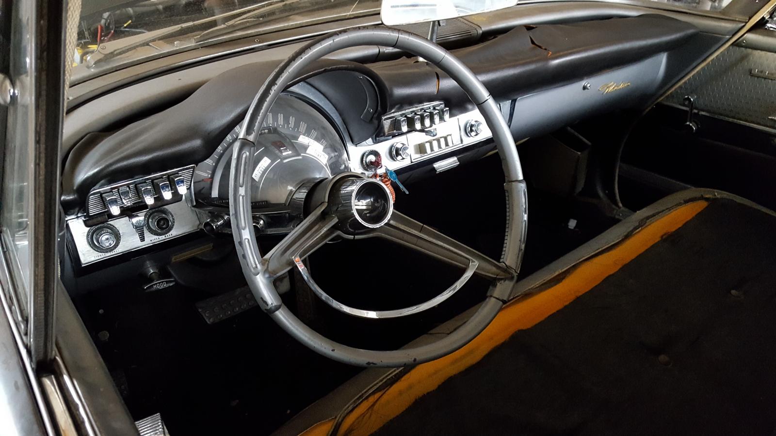
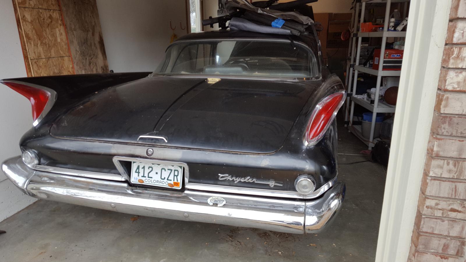
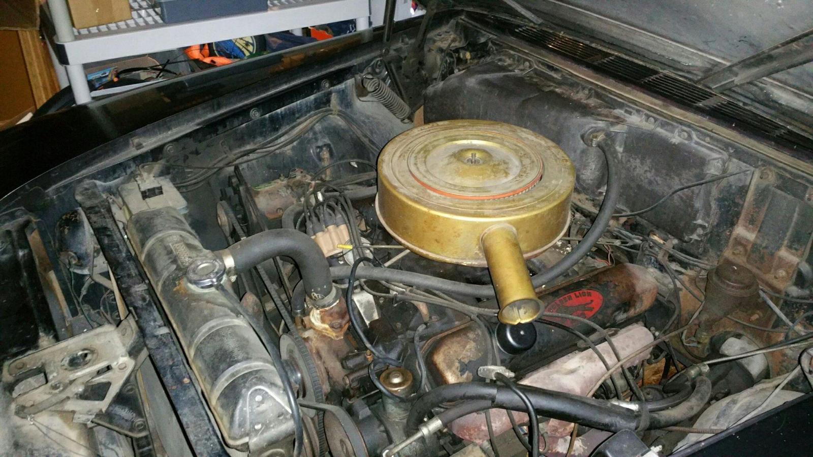
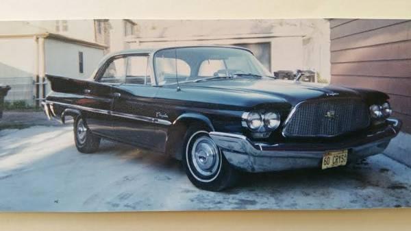 9 points9 pointsI know here shortly this will be added to the article database. I just got done rebuilding the front drive shaft. Rather easy task and the parts are easy to common by even to rebuild the cardan joint ball. Also forgive me I got the camera lens greasy on my phone. Before you break down the double cardan joint mark it so you get it back together the same way. I used a file a scratch a line across all the pieces. It hard to see but there is a line across the left joint cap, the middle joint and the rear joint cap. Now using my Harbor Freight Ball Joint Press I'm simple driving the cap out the other side and disassembling the double cardan joint from the flange end working towards the shaft. When you take it all apart now check your centering ball and bearing. Mine was in sad shape. As you'll see all the needle bearing fell out (ashtray) and no grease was left. So I made a cal to the local NAPA store and they had the centering ball in stock bit pricey at $80 but I needed. It made by SKF and part number is UJ617. Now you need to clean up your old end remove all the grease and dirt. I piled up a good goob of grease in the bottom before installing the ball. Now using a socket to drive the ball into the joint end. Now drive your seal in place with the same socket just do it very light tapping with your hammer or small ball peen. Now the grease should of been shoved into the needle bearings. You notice there is a small hole for the grease to ooze out the bottom and filled the needle bearings. Now start to assemble your u-joint is the shaft. Again using a Harbor Freight Ball Joint Press which is awesome because you'll never have to strike the drive shaft with a hammer or worry about needle bearing to falling over. Now during this process the first cap I will drive too far to the other side but not out of the yoke. This is to push the cross over to the other side a bit more so when you place your other cap it already started on the cross arm and less risk of the needle bearing falling out. before driving it in place your clip on the first cap. Now I did things a bit different and assembled my last joint in the rear flange. What you have to do is place your spring in the shaft with a bit a of grease to hold it. Then tilt the ball just enough to so you can start the cross of the u-joint and the centering ball at the same time. Be patient there is enough room and it will go in. Finished product... So when you are done it should move in all directions freely without binding. Make sure to grease all your joint before installing the shaft. For the front joint I just used the vise and pump grease till the red was seen in all ends. Now install the front driveshaft... What a double cardan joint looks like moving...9 points9 pointsMy last thread had to do with a crappy end to crappy month. But today was different. I will let ya'll decide for yourselves. No whining about the dirt or the broken bezel, I already know.
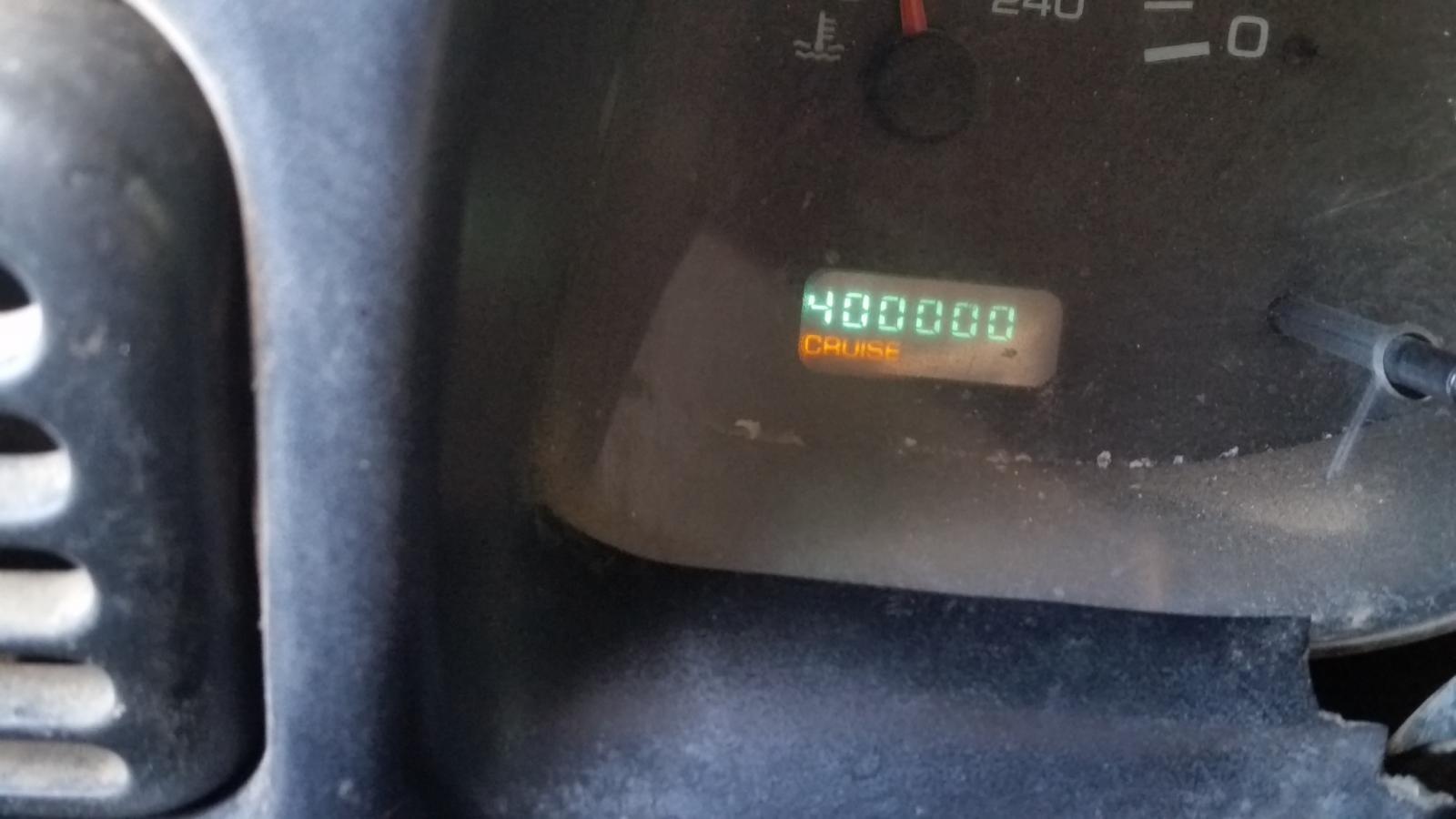 9 points9 points9 points9 pointsB-1 Bomber For Sale A B1 bomber was in here ( Billings , MT ) doing practice approaches and touch and go's. On one of the landings the pilot sets his brakes on fire. He taxis in, and the airport parks him on a taxiway and then puts cones around him until parts and mechanics can be brought in from Ellsworth AFB, Rapid City SD,the next day. The next day is a Saturday, which doesn't have much going on, so we get to laughing in the tower that maybe somebody should hang a For Sale sign on the plane. We convince one of our guys who's well known for doing things like this that it would be a good idea. So he takes off for the hardware store to buy a For Sale sign. On the way back he stops at a car dealer and gets one of those "As is/No Warranty" signs that hang in all used cars. On that sign was written something like low miles, new engines, needs brakes and tires. Those signs were taped together, and off goes our hero. He climbs over the fence, leaving some skin on the b! arbed wire, and makes his way the 1000 feet or so to the aircraft. As he's doing that, we see a couple of airport vehicles starting to gather with the recently arrived mechanics as well as the plane's crew. Not looking good for our intrepid airplane salesman. He gets to the nose wheel and tapes the sign to the nose strut. Then he starts to make his way back from the plane as the vehicles start to head out from the shop on the way to the bomber. Somehow he makes it without being seen. The vehicles arrive at the plane, and of course notice the sign right away. The Air Force guys are in stitches, funniest thing they've seen in a long time. Airport guys are not sure what to think. Airport management is livid as they've been tasked with security. Pretty soon a camera appears and all the Air Force guys are taking pictures of each other by the sign. Our hero is back in the tower now, and notices the bomber's commander is talking on a cell phone. Our guy gets on the radio to the airport truck and asks for that guy's phone number. As soon as he finishes that call, our guy calls the aircraft commander. When he answers, our guy says "I'm calling about the plane you have for sale." Aircraft commander about falls over from the laughter. It just so happened that the chief photographer for our local newspaper is a pilot and he may have been called prior to the sign being placed. He was told to get up here with a big lens. Here's one of the pics he got: http://farm4.static.flickr.com/3415/3315809933_35fa96d641_o.jpg An article showed on the front page of the Sunday paper. When that came out, the Colonel running Ellsworth called the airport director and read him the riot act, wondering what kind of dog and pony show he was running up there. We were later informed by the crew that the sign was framed and is now permanently mounted inside the aircraft. Hard to have that kind of fun anymore.9 pointsThis leaderboard is set to Boise/GMT-06:00


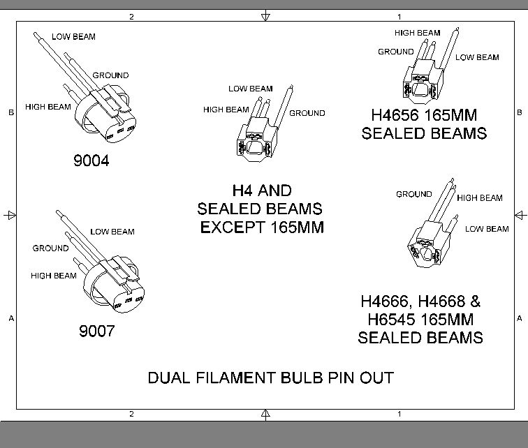
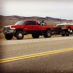
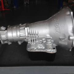
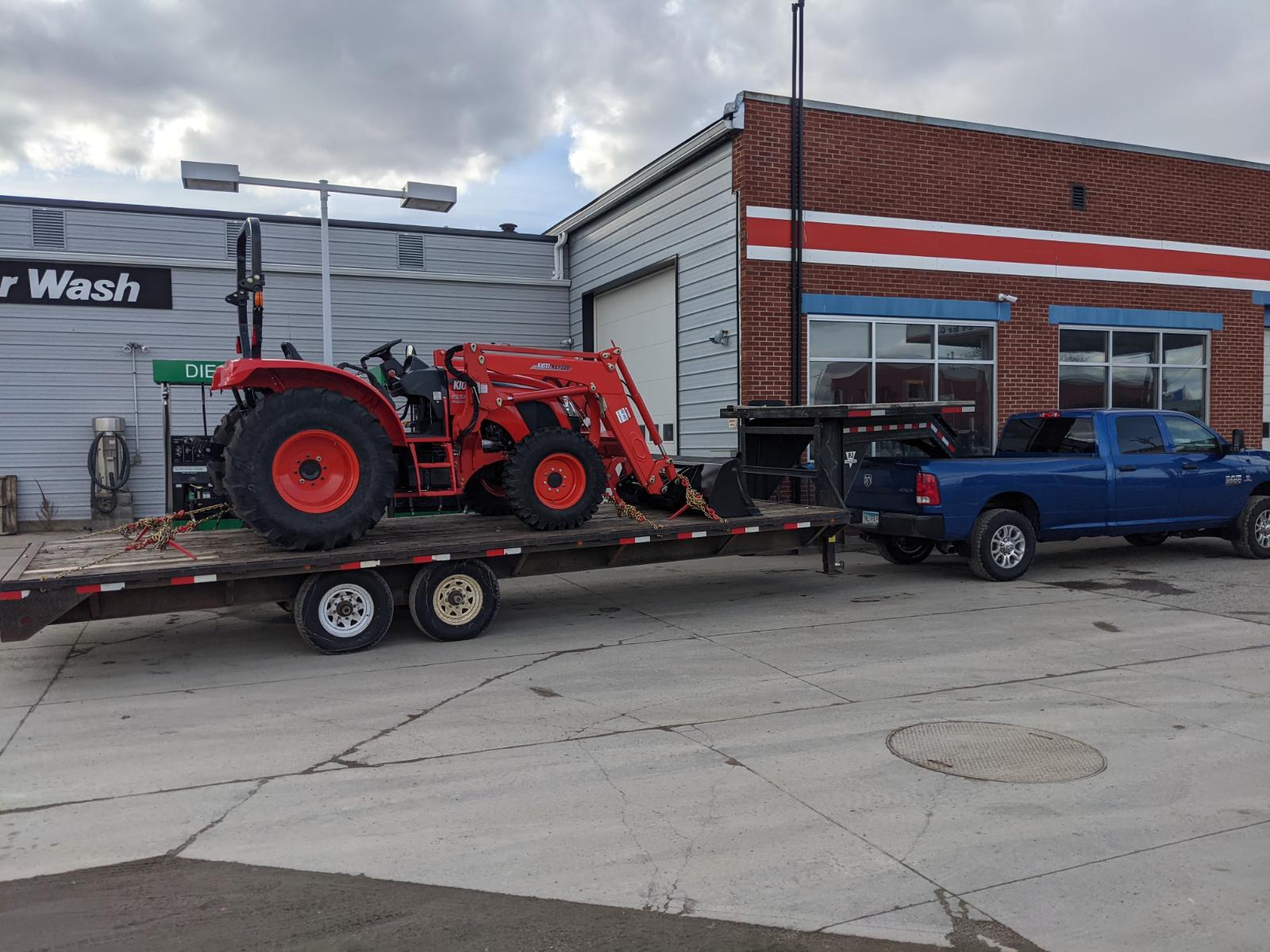

.jpg.90b458cd48d6bb8f095e4a405cb9cae1.jpg)


.thumb.jpg.9c48aa8f6cc163d8202f09ef46255c5f.jpg)
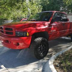


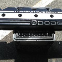


Account
Navigation
Search
Configure browser push notifications
Chrome (Android)
- Tap the lock icon next to the address bar.
- Tap Permissions → Notifications.
- Adjust your preference.
Chrome (Desktop)
- Click the padlock icon in the address bar.
- Select Site settings.
- Find Notifications and adjust your preference.
Safari (iOS 16.4+)
- Ensure the site is installed via Add to Home Screen.
- Open Settings App → Notifications.
- Find your app name and adjust your preference.
Safari (macOS)
- Go to Safari → Preferences.
- Click the Websites tab.
- Select Notifications in the sidebar.
- Find this website and adjust your preference.
Edge (Android)
- Tap the lock icon next to the address bar.
- Tap Permissions.
- Find Notifications and adjust your preference.
Edge (Desktop)
- Click the padlock icon in the address bar.
- Click Permissions for this site.
- Find Notifications and adjust your preference.
Firefox (Android)
- Go to Settings → Site permissions.
- Tap Notifications.
- Find this site in the list and adjust your preference.
Firefox (Desktop)
- Open Firefox Settings.
- Search for Notifications.
- Find this site in the list and adjust your preference.