


Mopar1973Man
Owner
-
Joined
-
Last visited
Everything posted by Mopar1973Man
-
Uhhhh.... I know this beyond my ability. @Quadzilla Power and @Quadzilla Marco Would be more able to fix this. The fuel injectors are huge. I'm not sure how to handle something that big. I'm in the 150 HP injector playground with a single (60/60/12) and much smaller tires at 30 inches and final ratio of 3.69:1. I'm going to suggest you upload your tune to the site so we can look over what you are running. I'm sure you're going to have to reach down really low in the CANBus fuel. Then the timing will have to cranked up fairly good. Take a peek at the articles... You might look at the big injector tunes we've got and try them... https://mopar1973man.com/files/category/22-quadzilla-standard-tunes/ Moved to Quadzilla Forum to get more eyes on the matter...
-
My lifestyle might be on the "struggling side" but I'm managing to survive in my humble way. I've managed to keep going.
-
I'm holding my head high and thinking positive. The Good Lord has a plan for me. I'm doing everything I can do to keep a balance in my life and not let the stress get me down. This has been a huge eye-opener for me. I had to do something about my blood pressure. I've managed to knock that back to near normal level huffing on the bicycle. Doing 20 mile rides now. I've even changed up how I grocery shop now. I'll now do as much as I can on the bicycle and then use the truck for bigger loads. Like Thursday needed toothbrush heads from WalMart so I rode over got them. Then rode back to the truck and dropped them off. Then rode over to WareMart and picked up a few things and rode back to the truck. Yeah not far barely a mile away. Sometimes I'll go to the other end of town for Albertsons and huff back with a few items. Yeah, I've done a lot to fix my health. Now as for cancer/tumor I'm pretty sure it going to be gone. The doctor wants to put a stent in the right ureter just to protect it from the damage it's taken. I've been still dosing with my herb at night and letting it do its job.
-
Ummm... It made from heavy steel. Should have built it out of aluminum. Weight takes HP to move.
-
I stay strictly stock and managed to get 150k to 350k from all the front end parts. My tie rod ends held up the best at 350k miles, my factory ball joints last over 180k miles. The track bar at 150k miles. Unit bearings over 150k miles. The key factor in seeing things last... DO NOT put on bigger wheels and tires! I've been under stock size for most of the life of my truck. Went from 265's to 235's and extended the life of everything. Now dropped the 235's and went an inch shorter with 245's. Now keeping the transmission and driveline happier!
-
Some 53 blocks don't crack. Ask @cajflynn about his 1.3 million mile Cummins with a 53 block. There is hope...
-
Weehaw... Even better news. St. Lukes hospital just sent me a letter stating that they are going to forgive 60% of my bill with them and drops it down to just under $6,000 for what my current bill is. Now let's see how the next surgery stacks up in this and this is a pill I can swallow. https://www.gofundme.com/mopar1973man-hospital-bills Or... On the website... https://mopar1973man.com/donate/make-donation/?_new=1&goal=11
-
Wish me luck... now going to be heading into my next surgery. That happens on Monday, March 25th at 11am. The doctor wants to put a stent in my right ureter and explore and make sure I'm still clean of cancer. This should be my last surgery.
-
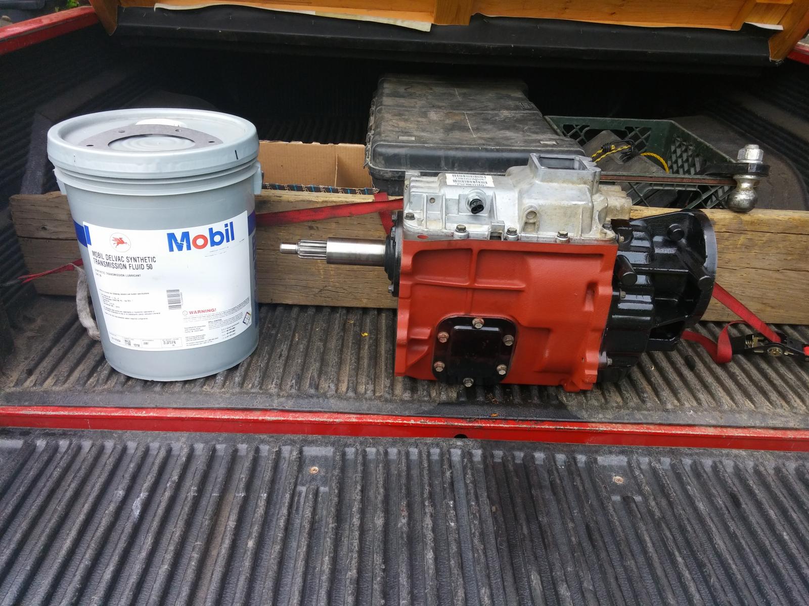
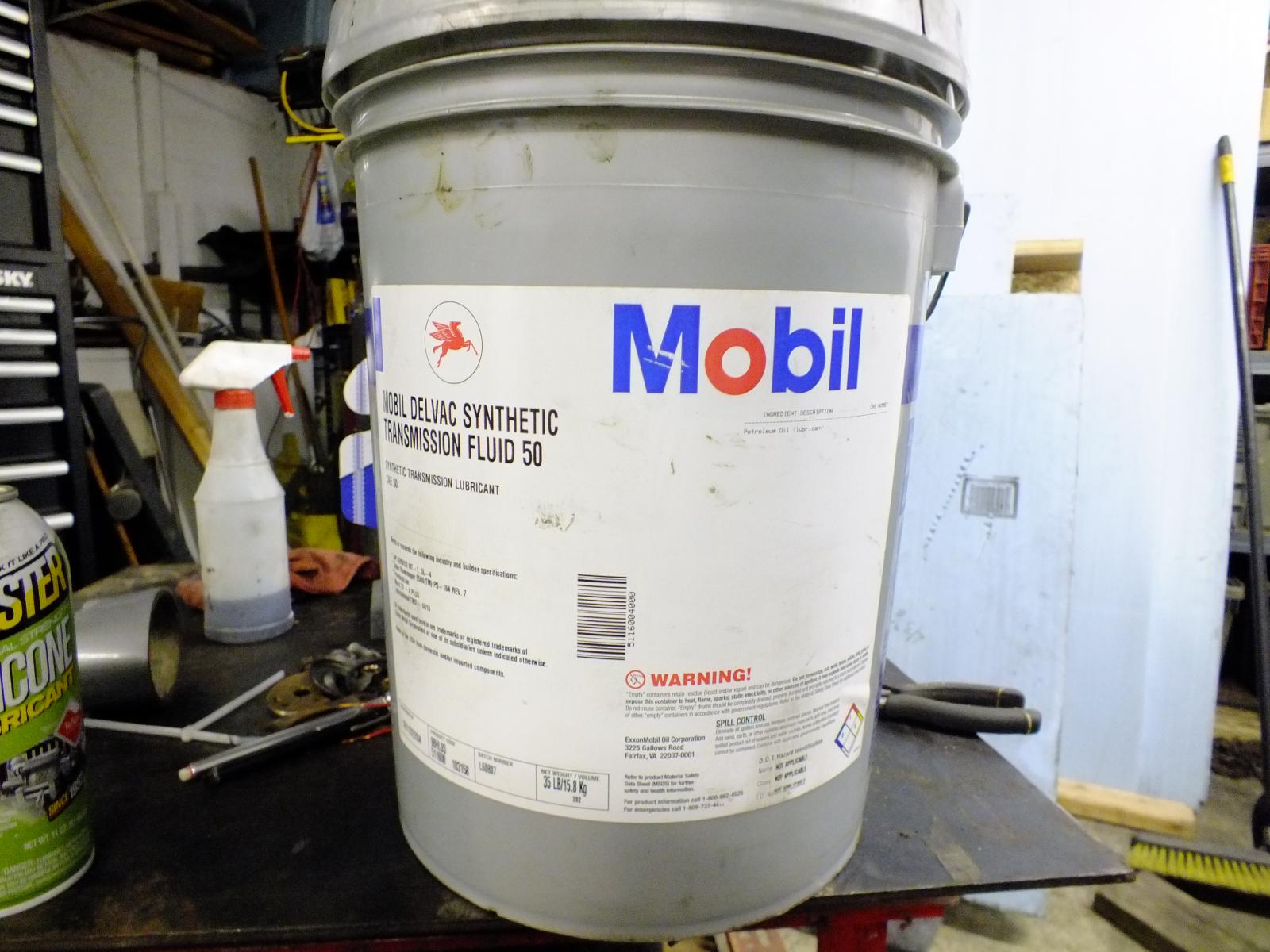
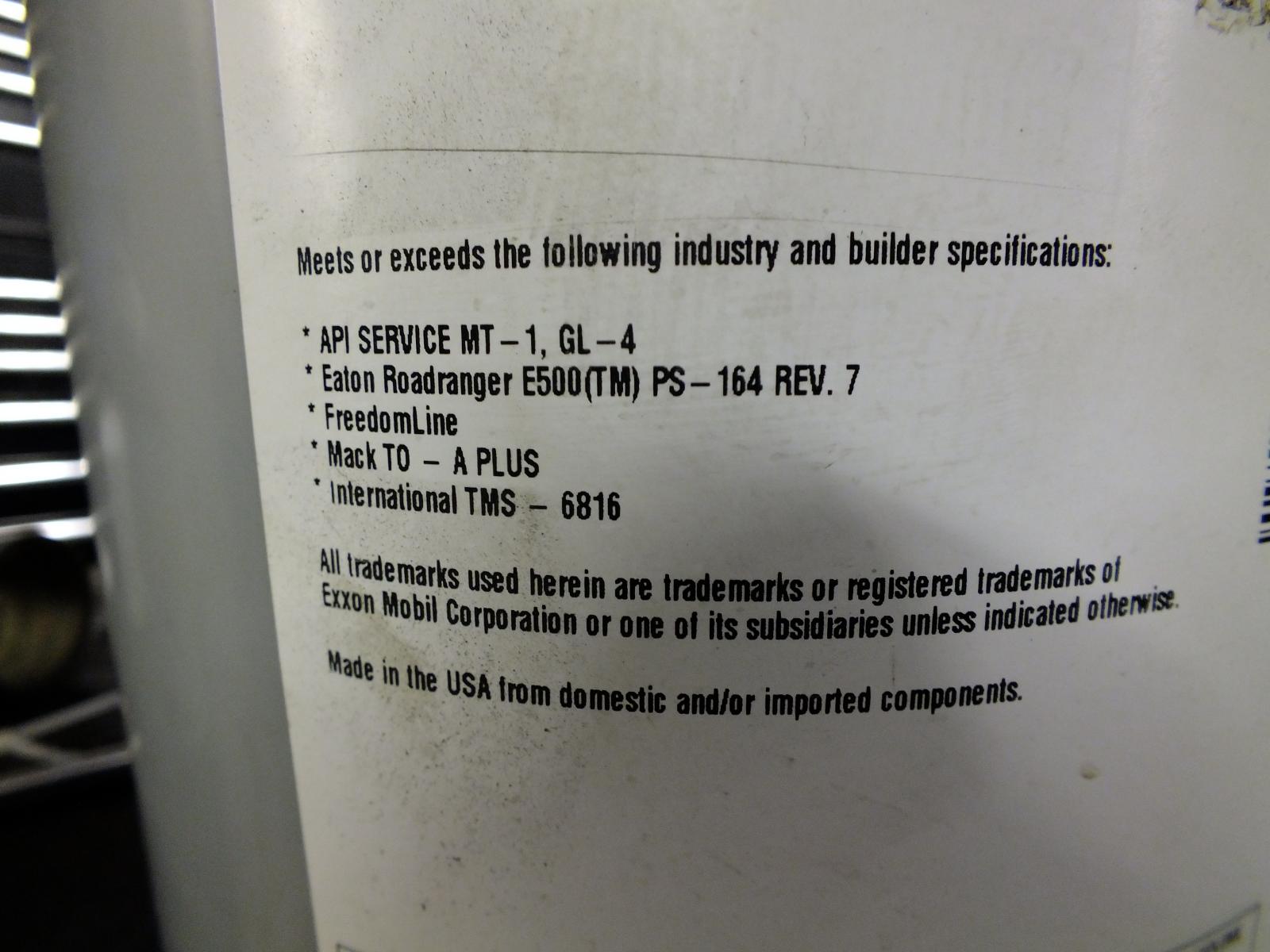
You'll find out that the oil will most likely be higher with the cooler on the passenger side unless you can wrap the exhaust pipe or install a heat shield. That would be more productive than the coolers.Just to make you think... That's all I really don't think there is anything that special.I still got serious doubt of how different it is being now Dodge dealer is now loading either NV5600 or NV4500 with ATF+4. Even the G56 in the 3rd Gens are now ATF+4. Must not be too special eh?Better off without it. Personally your just placing the heat closer to the oil. Then it would help to do some measuring of the oil first before buying coolers. I just spent 4 months where my oil temp never got over 100*F. Then in the summer time I rarely make it over 170*F even towing. Don't even need the coolers.Might want to catch the diff cover thread. Someone can point you to the videos. I'm on the road.4 inch chunk of exhaust pipe fits perfect. I've got a piece in mine.Mobil 50 SAE GL-4 Synthetic Transmission fluid. Same stuff used in Eaton Fuller 10 speed transmissions. I'm at 110k miles and still going... No shift issues even with winter temperatures down to near -30*F and shift like butter. Be aware 50 weight oil is actually 90 weight Gear Lube much thicker. Like 75w-85 for the NV4500 is like 10w-30 engine oil.
 The circuit breaker is only just in case the alternator diodes short to ground if so to prevent the wire from glowing and igniting a fire under the hood. So the breaker should be big enough for maximum charge amperage and cut the battery loose if it happens to short to ground.Yeah, but there isn't much truth there either. Being I'm one of the rogue owners that bailed out and went out on a limb to prove that there are much more options.Check back, Michael Nelson replied Tuesday at 07:44 PM is the reply...I did get the diode for your type of alternator...Yep... Alternator is moved to the passenger side and the ECM and VP44 ground moves to the driver side plus the gear case.Time to contact Quadzilla sounds like warranty issue.Error codes? Check with a scan tool. Report back the codes.


Account
Navigation
Search
Configure browser push notifications
Chrome (Android)
- Tap the lock icon next to the address bar.
- Tap Permissions → Notifications.
- Adjust your preference.
Chrome (Desktop)
- Click the padlock icon in the address bar.
- Select Site settings.
- Find Notifications and adjust your preference.
Safari (iOS 16.4+)
- Ensure the site is installed via Add to Home Screen.
- Open Settings App → Notifications.
- Find your app name and adjust your preference.
Safari (macOS)
- Go to Safari → Preferences.
- Click the Websites tab.
- Select Notifications in the sidebar.
- Find this website and adjust your preference.
Edge (Android)
- Tap the lock icon next to the address bar.
- Tap Permissions.
- Find Notifications and adjust your preference.
Edge (Desktop)
- Click the padlock icon in the address bar.
- Click Permissions for this site.
- Find Notifications and adjust your preference.
Firefox (Android)
- Go to Settings → Site permissions.
- Tap Notifications.
- Find this site in the list and adjust your preference.
Firefox (Desktop)
- Open Firefox Settings.
- Search for Notifications.
- Find this site in the list and adjust your preference.