Mopar1973Man
Owner
-
Joined
-
Last visited
Everything posted by Mopar1973Man
-
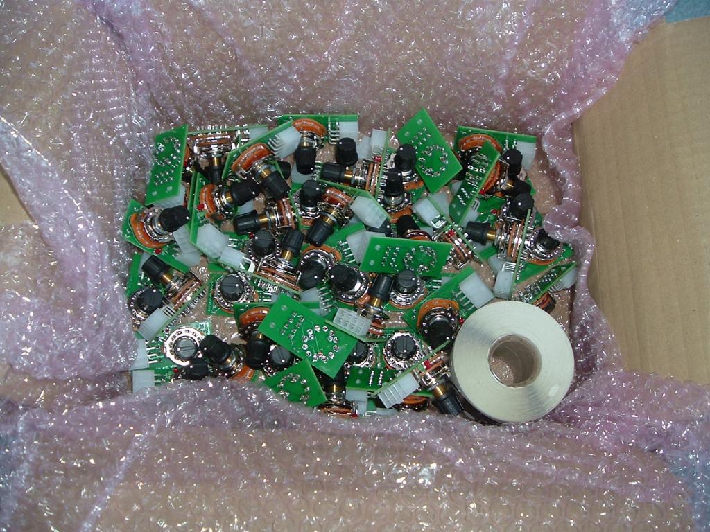
I called the cable manufacture I had him break it into 2 batch so we can get them sooner.
-
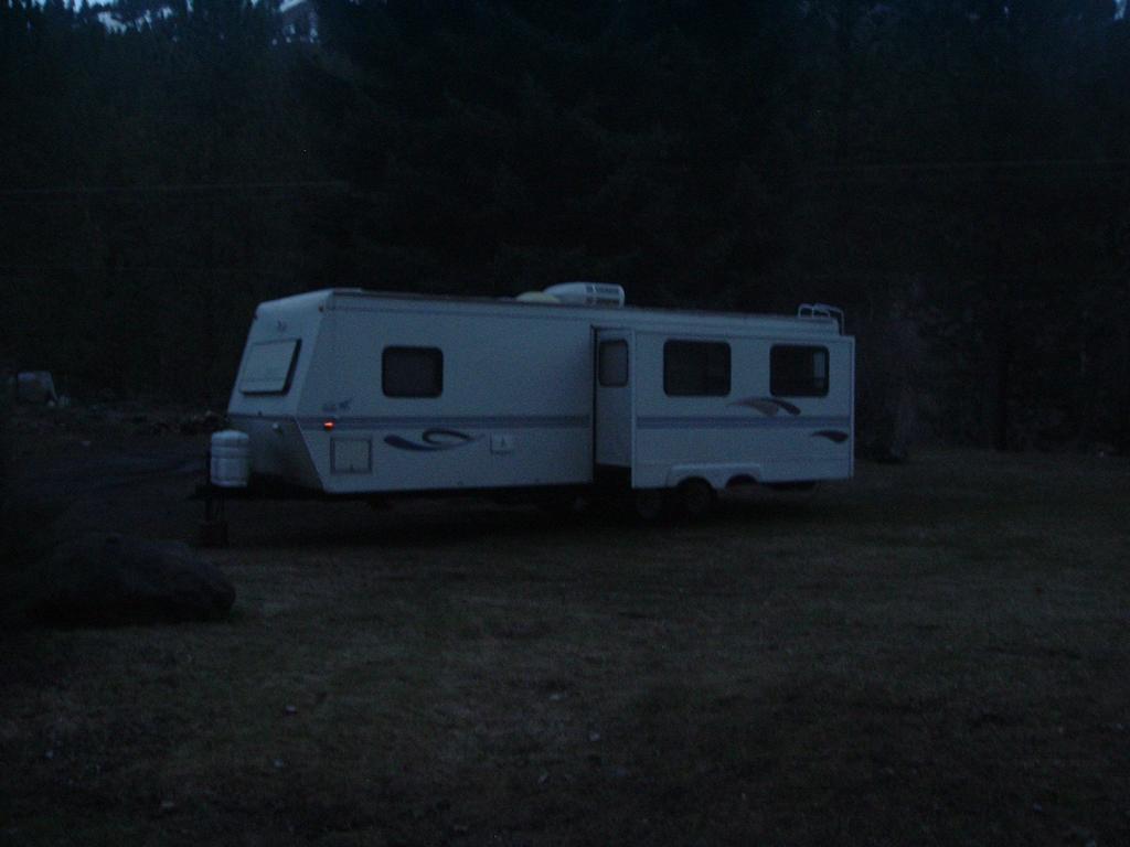
Weather getting so mild I've pulled mine out so I can start cleaning up everything from winter time. Might sneak out soon for a trip south. I've got to re-seal around my clearance lights and some of the trim. Darn delamination in a few spots. It's all your fault Nick you started a trend...
-
Don't have to buy the expensive hydros either NAPA hydros are just as good just you have to bleed the system before installing. I still suggest bleeding even sealed systems because you never know how it's been handled before it got to you.
-
Good idea to have a CO2 detector. It would really suck to go out for your first camping trip and wake up "dead" from the CO2 killing you. The only reason I ask about the venting is we got the same heaters in our #3 fire station and eventually burning propane smell get over powering.
-
Question how does that heater vent the exhaust?
-
No effect at all. I'm changing both the AirDog and Stock fuel filters at 60k miles now. I've got roughly 47k miles on my current filters and fuel pressure is still strong. Here is my last change at 30k miles.
-
Not that they are wrong its that the Cummins Diesel sensor typically is not in the list. Now thw one you listed is a proper gasoline engine sensor.
-
Holy ____ !!! I guess i 'm not buying a NAPA sensor... http://www.napaonline.com/Catalog/CatalogItemDetail.aspx/Oil-Pressure-Gauge-Switch/_/R-ECHOP6725_0464379499
-
IBMobile... Watch out. Those are gasser oil pressure sensors. I've made the same mistake. A Cummins oil pressure sensor typically sells for at least $100 bucks. Even NAPA Online miss list the sensors for our truck. It's off by one digit on the part number.
-
Absolutely. Very simple video but proves a good points. 2 Cycle oil leaves behind a lubricant for the engine to stay lubed up cylinder wise where cetane booster and other products tend possibly leave behind other soot debris. Now take notice of the other thing in the video is time of burn. The 2 cycle oil burns slower and longer being it has way more BTU's per quantity vs most fuel additives. As cetane goes up the fuel goes down in BTU's. So 2 Cycle Oil will produce more work vs. high cetane boosted fuels. Take notice every winter when fuel cetane spikes high for the winter time everyone loses MPG's. Why? Simply put the BTUs went down and the working force of the fuel was lost. So now as summer comes and cetane lowers again MPG rises. http://www.fuelexpert.co.za/2strokeoilindiesel.php As for the link site... https://www.google.com/maps/place/Sasolburg,+South+Africa/@-31.4049951,26.4103857,5z/data=!4m2!3m1!1s0x1e945e71a359dc29:0xa333dd792f4638a6 Again... South Africa has different vehicle and fuel requirements and also fuel standards... 0a. lastupdate : 2015/02/07 11:40:09+02 0b. emailsource : domain@fuelexpert.co.za 0c. emailposted : Fri, 6 Feb 2015 10:43:46 +0200 0d. emailsubject : fuelexpert.co.za 0g. historycount : 4 0h. invoiceno : 0 0i. contracttype : NEW 0j. rcsversion : $Revision: 4.18 $ $Date: 2015-01-20 10:05:00 $ 1a. domain : fuelexpert.co.za 1b. action : U 1c. Registrar : ZACR 2a. registrant : Fuel Expert 2b. registrantpostaladdress: ,-, , , -- 2c. registrantstreetaddress: 2d. amount : 0.00 2e. paymenttype : I 2f. billingaccount : Fuel Expert 2g. billingemail : domain@fuelexpert.co.za 2i. invoiceaddress : Sasolburg 2j. registrantphone : +27.166483707 2k. registrantfax : 2l. registrantemail : domain@fuelexpert.co.za 2n. vat : 3b. cname : 3c. cnamesub1 : 3d. cnamesub2 : 3e. creationdate : 2010/09/27 14:22:55 4a. admin : Fuel Expert 4b. admintitle : 4c. admincompany : Fuel Expert 4d. adminpostaladdr : Sasolburg 4e. adminphone : +27.166483707 4f. adminfax : 4g. adminemail : domain@fuelexpert.co.za 4h. adminnic : 5a. tec : Fuel Expert 5b. tectitle : 5c. teccompany : Fuel Expert 5d. tecpostaladdr : Sasolburg 5e. tecphone : +27.166483707 5f. tecfax : 5g. tecemail : domain@fuelexpert.co.za 5h. tecnic : 6a. primnsfqdn : ns1.stablehost.com 6b. primnsip : 6c. primnsipv6 : 6e. secns1fqdn : ns2.stablehost.com 6f. secns1ip : 6g. secns1ipv6 : 6i. secns2fqdn : 6j. secns2ip : 6k. secns2ipv6 : 6m. secns3fqdn : 6n. secns3ip : 6o. secns3ipv6 : 6q. secns4fqdn : 6r. secns4ip : 6s. secns4ipv6 : 8a. netblock1start : 8b. netblock1end : 8c. netblock2start : 8d. netblock2end : 8e. netblock3start : 8f. netblock3end : 9a. description1 : 9b. description2 : 9c. description3 : 9d. description4 : 9e. description5 : 9f. description6 :
-
Master ground for the main computers is on the passenger battery for the ECM, PCM and VP44.
-
Here is the wiring for it...
-
Sounds like EPA hype... I've seen that one before. Being I'm over 200k miles on 2 cycle oil and no such injector fouling has occurred. No injection pump or injector failures. Their stated HFRR results are wrong too. When you do a search for any US manufactured diesel fuel you find ALL US fuels state they score 520 HFRR typically. Back to Bosch standards which is 450 HFRR or less. Now are playing ball in our own nation and US fuels do NOT meet the designed requirement of Bosch Injection Systems. But if you look at the study they are all over the map and vague. Let talk about US diesel fuel and US vehicle requirements and things change. But now go global and toss in the differences between EU and US in diesel fuel standards and vehicle requirements worlds of difference. What US 520 HFRR Fuels can do. 80k miles on 2 cycle oil.
-
So he's got training wheels...
-
Why not just drive the Cummins? Fuel is cheap...
-
You might grab a GPS and compare your Speedometer and odometer for error. The gearing difference cause by the tires will change shift points and lockup. Might check with a GPS to see if the calibration is right. So many people assume that programming the tire size will be correct. Then find out afterwards the speedometer is still off because brand A and brand B 35" tires might differ by 0.5+/- so the revs per mile can be different. Just like my example 235's vs 265's is only 1 rev per mile difference by my Garmin GPS V can see the 0.5 MPH difference. Even my ScanGauge II can show a odometer error between the two.
-
Now its a oil with the expense of full synthetic you got to dump because of a leak. Just like all synthetic oil users they won't let go of that expensive oil even when they need to. So you got the choice of living with the leak and constantly adding oil to the engine (adding up cost) or dump the entire thing and fix the oil leak (another expensive oil change). Bad idea is trying to capture and reuse the oil. Too much risk in falling debris landing in your catch bucket/pan.
-
Out here since good fuel is long way in between so I typically go for quality name brand fuels and skip the Mom & pop places just too risky. So at times I do run below 1/4 down to Empty if I know I can make it to a large city or quality place.
-
If it was standard petroleum it wouldn't matter just do an oil change...
-
I did tank drop removal and then installed a old school draw straw and still retain the full use of my tank right down to Empty and no real 1/4 issues everyone cries about. As you'll see my tip looks like its touching the bottom but its really not. It the thickness of a quarter between the tip and the tank bottom at empty. Now as a I fuel the bottom deflects downward and away from the tip. Diesel fuel is roughly 6.5 pounds per gallon so 10 gallons will be 60 pounds of weight so the bottom deflect a good 1/8". Also notice there is no wild angle cuts or anything weird with the tip other that 4 small notches added.
-
I've seen a TSB about using a bead of silicone sealant for the rear part of the pan. Did you use a sealant on the oil pan gasket? A light color block paint would of help seeing the path of othe oil leak. I think I've mention this before...
-
Even with my AirDog I kept my old Big Line Kit from Vulcan so I've got the fittings and wiring extension so I can hook a stock pump in with little effort. Unscrew the AirDog lines and hook up the stock pump and electrical. Done. Still operating on the 1/2 line and still removed all the junk banjos. But still have an option for stock or aftermarket. With any upgrade pump you will have to change the pickup assembly in the tank you have no choice. Even the stock non-pump sender is not big enough for any lift pumps.
-
Then you should see the 2001 in my shop right now with ZERO PSI of fuel pressure. Still starts and runs like no issues and even got a Edge Juice wire tapped. No fuel pressure sender install. Really lame.
-
Valve Lash Adjustment For Cummins Valve lash adjustment is suggested to be done at 150K miles which I think is too far down the road. My valve lash were out of adjustment a bit at 92K miles. So this is how I did my valve lash adjustment on my truck. Valve lash adjustment is fairly simple to do and doesn't require much for tools. Tools Needed: 1. Feeler gauge set (0.010 and 0.020) 2. 9/16" box wrench 3. 10mm short socket 4. 15/16" socket 5. both 3/8" and 1/2" ratchets 6. Allen wrench 7. mirror. Valve lash adjustment should be done on a cold engine with a coolant temp below 140*F. The first thing you need to do is pull the valve cover off the engine. You'll need a 10mm short socket and a 3/8" ratchet. Loosen all the bolt till you can lift the bolt up. Don't bother removing the bolts from the valve cover. Once you got that the valve cover will come off on the passenger side. You got to slide it towards the turbo and work it over the top of the heater hose. Take your time is will go... Now you need to use your 1/2" ratchet and the 15/16" socket to rotate the alternator. You want to turn it towards the passenger side (or towards coolant bottle). You want to get the gear to be in the TDC (Top Dead Center) like in the picture above. Now you'll start adjusting valve lash. Intake valves 1, 2, 4 and Exhaust valves 1, 3, 5 which I've circled for you. Just remember the long rockers are exhaust valves and the short rockers are intake valves. Using a feeler gauge you want to adjust all intake valve lash to 0.010" gap and all exhaust valve lash to 0.020" gap. You'll be inserting the feeler gauge like shown. This is the part you got to take your time on. As you'll notice as you tighten up your adjustment screw the feeler gauges seem to be pinched in-between but try to hold the feeler gauge flat you'll notice it get loose again. So take your time... Now when you get ready to tighten the lock nut or finger spin it tight. Then as you tighten the nut you go to hold the adjustment screw still. But if you notice your gap is loose twist both nut and screw tighten a little bit. Or twist the adjustment screw loosen as you tighten the nut. This will increase or decrease the gap a little but not much. Now that you done this set now you go to do the other half of the valves. So now twist the alternator some more till you see (BDC -Bottom Dead Center) for the Bosch VP44 injection pump gear. Now adjust the rest of the valve lash. Intakes 3, 5, 6 and Exhaust 2, 4, 6. They are marked in the picture below. Again remember the long rocker are exhaust valves and short rockers are intake valves. Double check all the jam nuts that they are TIGHT! Mopar's Notes: Also wouldn't hurt to throw in the torque specs for the lock nuts on the adjusters. 18ft-lbs for the adjuster nuts and 18 ft-lbs for the valve cover bolts starting in the center out. inlinecumminspower http://idahoturbodiesels.com/vb/showthread.php?t=7665 You now have completed a valve adjustment on you engine. Now you got to reassemble the valve cover. Replace the gasket if it damaged typically the gasket is serviceable for many years. Then remount the breather cover on the gear case and hook up the vent tube. You'll hear a slight difference when you start the truck up. It going to be a bit quieter. Let it idle a bit and double check your valve cover for leaks.
-
Yes Sir...