Mopar1973Man
Owner
-
Joined
-
Last visited
Everything posted by Mopar1973Man
-
Calendar entry has been made for the Site. Might want to click if your going or not.
-
Thanks Nick. That would be insulting to use a "Idaho Potato" for a exhaust brake.
-
Personally think they need to be moved to the article database to be saved.
-
That's why I love my Edge Products boost elbow. No adjustment and does like it should and provides 35 PSI boost pressure. I've got an adjustable boost elbow in my toolbox but hate that darn thing 1/16 of a turn could change boost 5-10 PSI. A matter of fact I got to order a boost elbow for the truck in my yard. Edge only wants $10 bucks for the elbow.
-
Correct. I use mine quite a bit for exactly what you asking about. I go into the back country to help ranchers from time to time. So spend the night at a remote cabin and get pu in the morning to a windshield loaded with snow and ice. Kick the exhaust brake on and 3 cylinder high idle and pop the EGT's right up to 800*F and heat in the cab in about 5 minutes.
-
Dream on...
-
Let's say the big panel 400w array in the yard on a overcast day. I'm lucky if I charge at 3-5 Amps @ 26.4 VDC. Best is 15.1 Amps @ 26.4 Volts for 400 watts.
-
I can't understand why anyone would mount solar panel on the roof of the RV? Then that means you have to park in the sunny area for the solar panel to work meaning the interior of the RV will be hot during the summer. The gent that cuts my hair did this exact same mistake. Now he complains on how poor the panels work. No duh... Parking in the shade of a tree to keep the RV cooler now the solar panel is worthless. This is why I went to free standing you can park in the shade with the RV stays cooler and put the panels in the sun.
-
Yes. Just like you need a voltage regulator for your alternator. Yes. Consider your size and weight. They are glass faced so make sure you con sider where it going to be stored. Yes. Positive and Negative from the solar panel(s) to the solar controller then another pair of positive and negative from the solar controller to the batteries. Consider your voltage loss in distance too. So your distance of cable will have to be considered. Like here at the house I've got eight 50w panels for a total of 400w = 26.8 Volts DC x 14.9 Amp DC pretty light duty. But the run from the pole to the garage is about 120 feet and requires 2 ought cable. So if the panels have 26.8 the far end will be 26.4 volts at 120 feet. http://www.calculator.net/voltage-drop-calculator.html The black box on the right is my solar controller, above is the main breaker to the batteries. White large box is the master feed breaker to the inverter. (200 Amp DC). As for solar size it about how fast you can recharge the batteries. There is panels out now that for a single panel you can get 300 watts. Matter of fact I'm pulling the eight 50w panels soon to upgrade to four 265w panels (1,060 watts). Need better recharge rate in the winter time. For an RV. my cheapy Harbor freight 45w panel set and solar control is more than enough power to take care of a a old school 13" CRT TV, DVD player and all the other 12V RV stuff I got on board like water heater and fridge. So that controller is 45w = 13.2 VDC x 3.4 Amps DC. It stops right about 13.2 volts typically. So a good quality 100w panel would be killer. 100w = 14.0 VDC x 7.1 Amps DC nice mellow charge rate.
-
Like my cheap harbor freight solar panel controller has one USB ports and the Harbor freight 1200w has one USB port.
-
Easier yet just do the AC voltage test every oil change...
-
Most of these are just over glorified crooks. I'm not impressed with most of them. Trump is... Well... Um... OK. Hillary absolutely NOT she need to go to jail. Obama also should go to jail.
-
My old 76 Dodge motorhome was fairly basic. 12V lighting, water pump, AM/FM radio, and propane radiant heater, water heater, fridge, cook stove. That was a wonderful RV house battery would go for nearly a week with light duty lighting inside. Propane wise I've manage to survive in 0*F winters and two 20# propane bottles would barely get me a week. The new Jayco is more power hungry. Everything is electronic. From just putting LEDs in the bath room that was a huge power saver.
-
20# bottles are fairly cheap. Depends on what size the cabinet holds. I'm going to assume 20# bottles.
-
That's the basis of my design. Cheap power and low power usage. Mostly have the solar for recharging the batteries for lights, pump, and furnace (forced air). I added the inverter because then if I want to charge a cell phone, tablet, etc I can. Again low power usage. I do have a portable TV and DVD play for the night is just too quiet I can watch a DVD movie if I want. Still converting to LED lighting yet...
-
Better the Hillary... Anything but her! Please!
-
Catfish Junction - http://www.catfishjunctionrvpark.com/default.asp?file=Home
-
I wonder if there was a way to just order the diode packs from Nations alternators?
-
Bingo... Here we are back around full circle just the way I see it too. Why not fix the actual issue than band-aiding over the top with add-ons. Still ask the same question. Why is it that these truck went for years without a issue and now all of a sudden requires add-on band-aids, modification, etc.? I would start back at resolving the issue at hand first. But I would start looking at better quality diode packs on the alternator. http://www.fostertruck.com/diode-pack-rectifier-bridge-for-dodge-denso-alternator.html
-
Now the actual story...
-
I've got typically MPG, Total for the Day MPG, Total for the tank MPG and a random 4th. Like right now its IAT. As for setting them go here... http://www.scangauge.com/support/user-manuals/scangaugeii-user-manuals/ Then go to page 42 and read up on setting the XGauge.
-
Thanks that is killer someone is making replacement replacement seat motors. http://www.2men1garage.net/index.html
-
Here is the article on it as well.
-
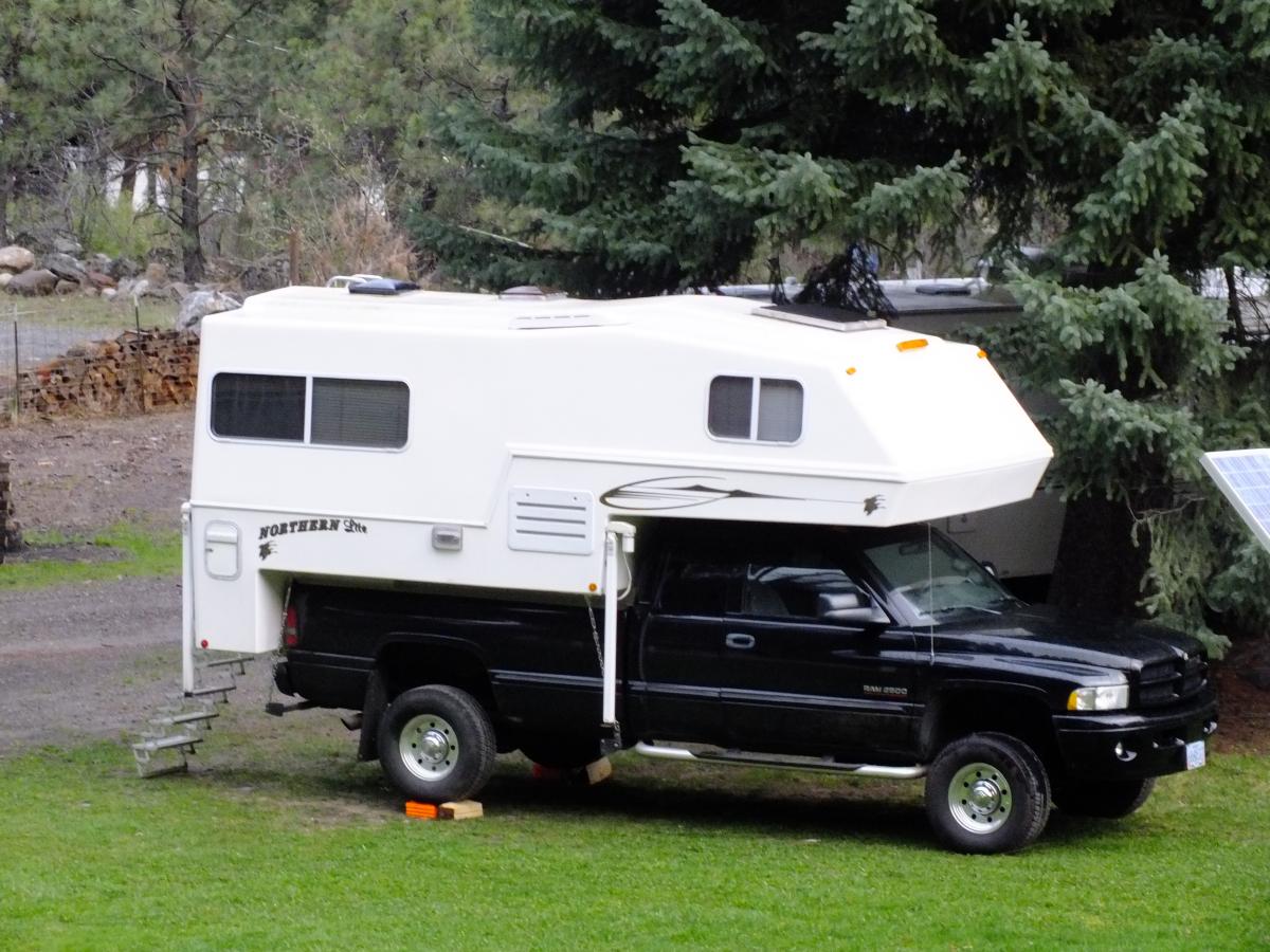
I'm pretty sure JAG1 will share his spot in my yard with you.
-
Here is JAG1 setup... Now we got to get Nick up for the summer event... Plenty of room in this park to gather.