Mopar1973Man
Owner
-
Joined
-
Last visited
Everything posted by Mopar1973Man
-
Nope. I just use a mayo jar and bleed them that way no need for the ABS pump and never had any issues using my method on any vehicle yet.
-
Actually I love my older truck now. Easy to repair and wouldn't want a new truck. Just a bigger target for thieves. Being the older truck with a few body issues most don't want to mess with it. Something new looking and fresh it will be a target fast.
-
If there is no wire tap then that whole section is not used. Another thing level 0, 1, 2, and 3 are not using wire tap section either.
-
Front right brake hose is opened up and leaking. Easy fix and need to bleed the system anyways...
-
So the ECM is relay protected. Be aware the lift pump ground and fuel heater ground is behind the starter.
-
I had the experience of installing two sets of bilstein shocks. In neither vehicle i was not impressed. Stiff ride. But that's what customers want. Me I'll most like go back to Ranchos 5100 being the lasted so long, never leaked oil and softer ride. When you off road then you want softer shocks not stiff.
-
Must be LOUD. I've got a few that are loud and when animals can't sleep they move on.
-
That is one thing about KYB shocks they are not super stiff. That one part about Bilstein shocks being they are charged with more pressure makes for super bumpy ride especially like washboard dirt roads. A softer shock is much better and doesn't beat you to death. Both the Rancho 5100 lasted a super long time and the KYB are going good too no excessive bounce at all. I've got KYB on both Thor and Beast.
-
Washer shim... I got a few small washers that don't restrict flow but just tightens up that spring a bit more. I just the same on my AirDog since the fuel pressure was sliding off a bit so I tweaked the spring a bit and then reassembled and got 18-19 PSI no issues.
-
I ran Rancho 5100 for over 200k miles no issues. Now I've got KYB's and still doing good. I just don't see the money for Bilsteins shocks they are not that good in my opinion.
-
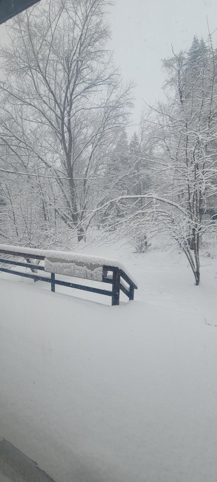
I'm going to hitch this up to my truck and haul out to Ohio and let you have it. I'm done with this crap. Global warming please come I'm tried of the freezing cold.
-
@IBMobile hey you need to hitch that up to the back your Cummins bring that warm weather up here. Jet boat race were canceled today due to snow. We are trying get get warm.
-
Bring me the global warming please... im freezing to death.
-
@Doubletrouble I think you bad luck is rubbing off on me. I had a friend show up and noticed my brake fluid is very low. Now it snowing and I've gotta figure out where the fluid is going.
-
Remember I got that sensor in the oil filter housing to measure the engine oil temp.
-
With the early version of 215/85 R16 for one tons. Both 215 and 245 are 30 inch tires.
-
98.5 to 2002 typically was 265's but when my door sticker was 245/75 R16. Still in all I count from 265's.
-
That is a stellar looking engine harness. Could you possibly tell me what you paid for that service? Being up here the ranchers tend to butcher the electrical and sometimes the only way to fix it is to just pull the wiring out and let @Auto Computer Specialistdeal with it. After seeing that above I'm sold... Very professional looking.
-
Too long on intervals. Aim for 75k tops. Long life is a joke being every cold start you dumping 600 to 700 amp over the coolant jacket and will charge coolant and start shifting the pH lower. Do not attempt to run the coolant to the limits. Either test with pH test straps or DVM. If you can measure voltage between battery ground and red probe just touch the coolant in the radiator then it getting time to change. 0.4 volts change is required 0.2 volts borderline.. keep an eye on it.
-
Trans temp lead is touching metal. There is one lead that is with a ring terminal. Make sure it's not touching and metal. I'm using the trans temp and engine oil temp. Just double check that wire.
-
Another trick idea. Add a ISSPro EV2 trans temp gauge, also order the optional relay for the gauge. Now program you fan on temp and the trans temp gauge will automatically control the fans for you.
-
The little kit that comes from heater treater has a 9V battery clip for testing the motor on the blend door unit. Most of the time the shaft breaks so the motor just keeps running push the blend door full hot, then one tick back it reverses and keeps turning making it cold. I had this exact issue last summer with a customer. The plastic shaft broke flat so it attempt to work but the motor kept turning so either full hot or full cold no middle ground. This is due no sense of limit (hitting a stop). Temp fix I did was pull the blend door motor set the temp for the customer by just moving the blend by hand. Then when the heater treater came in installed and tested making sure it hit it limit and stop. Be aware there is timing marks inside the blend motor if it not in time it will behave very strange. Yeah I've skip that step once and had the timing of and it foul the limits would almost act backwards cold is hot and hot is cold as it attempted to adjust temperature.
-
Look in the part number book. https://mopar1973man.com/cummins/articles.html/24-valve-2nd-generation_50/part-number-lookup-tool-2nd-gen-24v/
-
Head over to heater treaters and get the blend door shaft. I'm pretty sure the plastic shaft broke and it not controlling the door correctly. Fairly easy to install. Pull the carpet back and cut a little square out of the foam padding. Using a Phillips screwdriver bit and a 1/4" wrench and remove the screws. Follow the calibration process of the gears and install again. It will work right again.
-
441k miles still running the OE water pump. The secret is frequent coolant flushes to keep the pH levels correct. What happen people don't flush the system often enough the pH level starts to drop on the acidic side and starts rotting the metals of anything the coolant touches. Now it starts eating the seals and once the acidic coolant gets into the bearing the water pump fails. No I've never used distilled water either creek water from my irrigation system or my well water. Again 441k miles still going on the OE water pump. No fancy coolant just NAPA green antifreeze or the yellow universal coolant.