


Mopar1973Man
Owner
-
Joined
-
Last visited
Everything posted by Mopar1973Man
-
Contact Borg Warner directly with the model number. https://www.borgwarner.com/home
-
My problem is I'm getting tired. I'm tired of fighting this battle alone most days. Everyone is at a very far distance. No one to discuss day to day issues and get another point of view. Frustrated trying to make the right choices in life but not sure what I'm doing is right? Is there another way? Another point of view? Maybe only if someone else is there share there time with me.
-
Educated guess... http://www.theboostlab.com/borg-warner-s300-stage-1-turbo-package-1/ In the model number I just spotted it its a Borg Warner S300 turbo.
-
No. I didn't even know the seal where laying in the bottom till the head was dump on its side for the entire night to drain. You would have to remove all the springs to check. You can pull all the springs without pulling the head. At that point, you most likely end up pulling the head because of valve guide wear.
-
Personally I would avoid it. After the local ambulance running that system and all the problems with air compressors and leaking air bags... Ill stick with springs.
-
I've even got a write up on that...
-
Like I always said before... Sensor ground is NOT battery ground. You cannot interchange them or assume that they not one and the same.
-
Also creating more voltage drop and less noise shielding. The One thing @W-T and I agree upon is grounds should be as short as possible not to the battery per se but to body ground metal. Not everything must go to the battery directly. Battery post would look rather hairy if EVERYTHING ran to the battery post.
-
Got that too. I've got a force ON switch for the backup lights so I can hitch in the dark. This functions the same way with the radio I can toggle that switch on the camera is on while traveling forwards. I'd hope so I'm a guy... Also, I happen to be the ring leader...
-
Now does this old phone have dual Bluetooth channels or just a single Bluetooth channel? Like my LG G5 has dual Bluetooth channels that allows for both the iQuad and Blueooth Stereo at the same time. If your phone is a single Bluetooth then it will be one thing at a time. Ether iQuad or playing music.
-
Nice ride...
-
I'm going to end up doing fresh seat foam here in the spring of the year. I'll see if I can get shop to fix my driver side seat where the fabric is wearing out. Right now it just not a good time to do this for me but needs to be done soon.
-
Even it does in 2 years then it only cost me $20 a year to use that thing. Still cheap as heck...
-
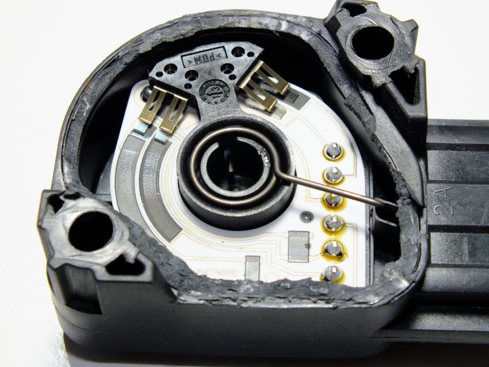
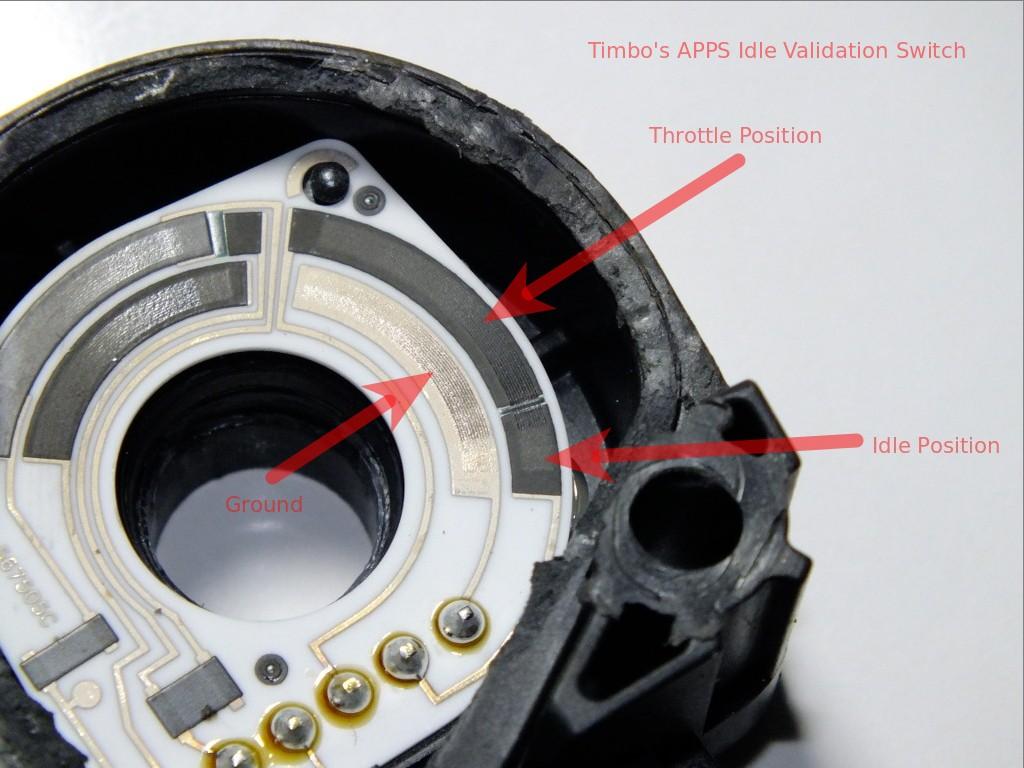
Idle should never be below 800 RPM period. When the Timbo's APPS is in IDLE mode the TPS should be ignored and the ECM idle software used.
-
Make sure to get ahold of @pepsi71ocean and let him know. I need to keep the list up to date.
-
Not a misprint. Pressing BND button only goes to FM1, FM2 and FM3. Being there is no FM or AM stations out here really in no big deal for me. I've got to be south od Council to get Boise radio stations and north of Grangeville to get Lewiston Radio stations.
-
Yes sir. Since I already had reverse light on the axle and the relay back there I just had to tap into the wiring.
-
Pretty simple. When power is applied to the camera leads then the camera is activated. When the video signal is seen by the stereo then the stereo mutes and displays the video from the camera. Simple too. Just came out of the stereo then through the firewall. Down to the frame and ran with the tail light wiring.
-
MAP sensor is the only one on the 5V lead. The oil pressure is a single wire.
-
@dieselautopower I'm considering sending my old 7 x 0.0085 and having a set of 7 x 0.010 nozzles again and then having them set for 330 bar.
-
The protection is mostly if the diodes shorts to ground there is something to pop. The alternator will never reach 140 Amp output or above.
-
TPS should show 0%... Hopefully, you DID NOT adjust for previous voltage. This is NOT REQUIRED on a Timbo's its a matter of getting angle right so the contact is in the IDLE position. As you'll see Timbo's APPS is a electronic free APPS sensor and does NOT use voltage for IVS (Ilde Validation Signal). It all about angle of the bellcrank! This is IDLE POSITION.
-
OK, chicken man,,, "Birds of a feather flock together..." So, you must be a big nut too... Eh?
-
Depends on the transmission for length. Remanufactured; 32-13/16" Long Driveshaft Info One of our most popular parts Front; Manual trans.; Trans. code NV5600; with Dana Model 60 Axle; with NV241HD Transfer Case Remanufactured; 28-9/16" Long Driveshaft Info One of our most popular parts Front; Standard Cab Pickup; Automatic trans.; Trans. code 47RE; with Dana Model 60 Axle; with NV241LD Transfer Case Front; Automatic trans.; Compressed Length of 28-9/16 in. measured from centerline of U-Joint located at the slip yoke end to the centerline of the furthest U-Joint on the opposite end, With NP241DLD transfer case, 1330 U-joint at differential yoke, 1.063 in. cap diameter Front; Automatic trans.; Compressed Length of 29-1/8 in. measured from centerline of U-Joint located at the slip yoke end to the centerline of the furthest U-Joint on the opposite end, With NP241DHD transfer case, 7290 U-joint at differential yoke, 1.125 in. cap diameter with inside snap rings Front; Manual trans.; 5 speed trans.; Trans. code NV4500HD; Compressed Length of 27-9/16 in. measured from centerline of U-Joint located at the slip yoke end to the centerline of the furthest U-Joint on the opposite end, 1330 U-joint at differential yoke, 1.063 in. cap diameter; New Venture trans. Front; Manual trans.; 6 speed trans.; Trans. code NV5600; Compressed Length of 32-13/16 in. measured from centerline of U-Joint located at the slip yoke end to the centerline of the furthest U-Joint on the opposite end, 1330 U-Joint at differential yoke, 1.063 in. cap diameter; New Venture trans.
-
14.8 volts x 190 amps = 2,812 Watts. This is absolute worse case.


