


Mopar1973Man
Owner
-
Joined
-
Last visited
Everything posted by Mopar1973Man
-
The whole idea with the wire tap is raising the line pressure to each injector. Which Smarty (or any programmer) can only do so much and has to play by particular rules by the ECM and VP44. The wire tap is where this extra control is found. I'll admit hands down Smarty is the best programmer for low end power and torque management control. I would have to agree if this new version is what they claim it is then yes, it would allow more control but at the cost of still stack with another module (most likely TST fuel only box) so you could most bang for your buck. I would have to say at this time Quadzilla Adrenaline and Edge Products (Comp or Juice) have the best fuel to boost management over Smarty at this current time. Still with bigger injectors you would still need a wire tap box of some sort to build good line pressure. "Assuming" the same limitaion is still occurring with the Smarty Pro series with 60-65 HP. It would give better fuel to boost control but still limited.
-
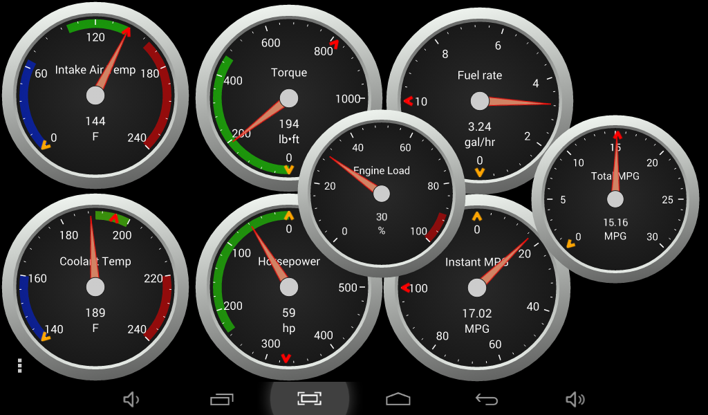
I added one with the RV towing back from Dynamics place. I was hunting for that one...
-
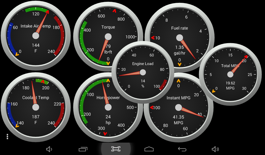
Here is calculated number from my last trip. The red markers show my high points. Correction this is empty running... Green bands is the stock HP / TQ area beyond that is extra. Again this is calculated at the flywheel. I found one during towing my RV.
-
Ahh... That where you got to be careful larger injector do pose their own problems too. Larger droplets, efficiency problems, etc. Same like CR people using rail pressure on smaller injectors again the high rail pressure makes for cleaner efficient burn vs. larger injectors. Kind of like if BBI injectors were produced for 24V another great product. But only CR engine only. After following BBI on how they build injectors worlds of difference from the dirty SAC injectors for our 24Vs. http://smartyresource.com/BBi2003-2004.aspx There was several articles on what it took to produce these injectors also how clean the spray pattern is. Then yes a good programmer would be able to help clean up larger injectors... Again waiting to see what will happen.
-
I know there is limitation of hardware not exactly sure what is the limiting factor being I've heard the Vp44 PSG or ECM hardware. Etc. If there wasn't any limitation why was Smarty only building 65 HP tuners all these years? After dealing with EFI Live tuners software modification is a mere few hours and flash your tune your ready to go. So the whole 65 HP limit is what I waiting to see if they can break through. Modification of fuel and timing table would be cool to be able to do for once. Just not really pleased with having to stack to get to use the Smarty. (Down side)
-
So there is a difference between the two as of current UDC and the pro series... Hmmm...
-
Some how I really doubt that will happen. Even the UDC for CR engines don't go that far RPM wise. Boost wise CR engine are allowed up to 40 PSI. I really doubt there will be that much for the 24V's. Accuracy of our MAP sensor is spotty at best about 30 PSI.
-
Really come issue out here in Idaho. Pack Rats will do the same thing if you don't rid of them quickly. One reason I stopped plugging the truck in. It made perfect habitat for rats and mice to hang out at night. "Ohh I'm bored. Nice wiring loom to chew on..." Munch, munch, munch...
-
You fine on the clutch. I'm running just behind you slightly at +50HP injectors and wire tapped on the Edge Comp. I tow heavy and never had a problem with my clutch which happens to be a Southbend Con OFE. It's never slipped. This all depends on your tire size. Oversize tires will put more stress on the clutch than stoc k size will. I'm designed to break the tires loose when I start reaching the threshold of the clutch so no damage occurs.
-
Being that like running 85 MPH on the interstate. I would be concerned. I would for sure be looking at the vacuum pump and vacuum lines as well as doing a compression test. @TFaoro Even with low miles you still seem to straight stream of vapor with some force. Where mine is more of drifty vapor. This might have something to do with how your engine was rebuilt. (Cam, compression ratio, etc.)
-
I'm pretty sure it's going to be the same old 60-65 HP output... I'm hoping I'm wrong too but general rule of thumb any non-wire tapped programmer is limited to 60-65 HP on 24V trucks.
-
-
@Me78569 is the producer of the lines he could answer more on that. Actually this one... http://www.summitracing.com/parts/atm-2260/overview/ I'm not sure what the sensor looks like being I'm trying to order a ISSPro EV2 gauge but even ISSPro web site doesn't show the sensor. But yeah it will look similar. Again @Me78569 is the producer of these transmission line kits. 1/2 ton truck. Typically its not a primary rig but it does work when the Cummins is down for repairs. So far I'm up to $1,500 on the transmission, then $75 in fluid. My pockets are rather empty now but now spending more on the bung and gauge. I made 160k miles on stock everything. I doubt I'll gain much from aftermarket pan.
-
Do a little research and see what can be done. I'm not sure what you'll have to do to get lock up in 2nd gear and doing a lock up controller (switch I mean). So talk to Dynamic and see what he's got to say. https://mopar1973man.com/forum/173-dynamic-transmissions/
-
Well the shift selector seal can be changed. what you got to do is drop the pan, filter and valve body. Now you can knock out the old seal with a hammer and screwdriver. Now to install the new seal use a long bolt and thick flat washer something that bend. On the bottom side you might need to use a second washer and deep socket. This will allow you to pull the new seal into place. As for the lines we have those for sale on the site here. The rest of the seals on the transmission I would talk to @Dynamic about it. https://mopar1973man.com/forum/173-dynamic-transmissions/
-
I thought your moving?
-
Problem your going to have... The Pacbrake lockup controller will only work in 3rd and 4th gears so only highway speed will work for the exhaust brake. Now if you modify your valve body for 2nd gear lock up you can gain more ability of the exhaust brake. I would highly suggest talking with @Dynamic about this so you get the best function with the least amount of damage to the transmssion. I asked him about doing lock up switch and I remember him mention about lock up shift is harsh on the transmission. So I would suggest talking to Dynamic on this.
-
LOL. Not much to program on a 12V... http://dieselautopower.com/blog/p7100-incab-tuner/
-
Exactly the same story I've heard too. At the same time this came out years ago EFI Live announced they will not produce a EFI Live programmer for the 24V truck because they are just too old. So everyone waited on bated breathe for Smarty to release UDC programmer for the 24V. Looking at the CR Engine Smarty its impressive tuner.
-
Thank you @TFaoro!!! I didn't catch his turbo. Yeah then you would be looking for a in-pipe exhaust brake not a turbo mount. It would be best to consider biting the bullet and buying a new unit that works for your application. Here is a vacuum exhaust brake and how it bolts up to the turbo.
-
Yeah. This is an air pressure driven system you are looking at. The vacuum unit looks differently typically with a larger vacuum can on the exhaust brake valve. So no the compressor isn't for on board air. I wouldn't suggest using it for on board air. 1/4 HP, 1.2 CFM is not a whole lot of air. Looks similar to Viair http://www.viaircorp.com/275C.html
-
Depends on how much you use the exhaust brake. Being I live in the mountain I'm constantly on and off the exhaust brake coming down long grades towing or empty. So that little compressor would be working hard with me in the driver seat. The only time i touch the brake pedal is to stop from a speed of roughly 20-25 MPH typically. So exhaust brake to me is my primary braking force where my service brakes are my secondary. I highly suggest you consider you mount location carefully. That little compressor will sound like the little portable 12V tire pumps you buy in auto part stores. I would opt for vacuum driven Exhaust brake then it just tee into the existing vacuum on the cowling and there is no extra noises then. Hmmm... Craiglist find or what? What kind of price on it? How old of unit?
-
When you test the fuel pressure hook up a gauge and then go drive the truck. We need to know idlng pressure then WOT pressure at highway speed. Still need to know if there is any error codes too...
-
I'm not sure about PacBrake. Some version had double valves and some are single valves. Personally it would drive me crazy listening to a little compressor running nearly constantly for the amount I use mine locally. I would look at the main butterfly valve and be sure its in good working order and the butterfly is not loose in the pivot.
-
Those are sweet little lathes you got there. Small duty but still can do quite a bit of work. All metal work is done slowly anyways.

