

Leaderboard
-
- All areas
- Events
- Event Comments
- Files
- File Comments
- File Reviews
- Images
- Image Comments
- Image Reviews
- Albums
- Album Comments
- Album Reviews
- Blog Entries
- Blog Comments
- Cummins Articles
- Cummins Article Comments
- Cummins Article Reviews
- Vendors
- Vendor Comments
- Vendor Reviews
- Ads
- Ad Comments
- Ad Reviews
- Policies
- Policy Comments
- Topics
- Posts
-
-
W-T
Yearly Subscription40Points146Posts -
pepsi71ocean
Yearly Subscription26Points1,199Posts -
Mace
Monthly Subscription6Points68Posts -
Gregturley
Monthly Subscription4Points568Posts


Popular Content
Showing content with the highest reputation since 12/14/2009 in Cummins Articles
-
After 18 years of interesting CTD enthusiasts and transmission specialty outlets all contributing their method, or fix, to the well known TC lock unlock syndrome, I can no longer remain silent. Extensive review of many posts regarding TC lock unlock, the rerouting methodes, the add on filters for APPS and last, but not least,...the "tin-foil hat" brigade. I do realize that each individual or company that contributed to the vast amount of information on the web had good intentions and I must acknowledge that some of the procedures caused me to closely examine what these people were trying to do. I believe it is well known that even a blind mouse occasionally finds a morsel of cheese. Again, as it is well known @Mopar1973Man was the only entity who positively identified the instigating source of this key issue. My entry today is not about alternators...it is about what Daimler/Chrysler did in regard to production of these Cummins powered platforms and the complete disregard of common sense Electronic Engineering. Please note, this applies to automatic and manual transmissions as each platform is plagued in the same manor with different quirks. This Blk/Tan #8 gage wire is quite critical in the scheme of things. It is contained within a 1" plastic conduit passing along the front of the engine. It contains water temp sensor leads, air conditioning leads, alternator/PCM leads and the #6 gage alternator charge line to the PDC. This #8 gage Blk/Tan passes over the top/backend of the alternator and is "eventually" connected to the Auxiliary Battery (passenger side) negative terminal. This snapshot of the Factory Service manual documents "four critical ground leads" that are "spliced" in an unconventional method. This photo depicts the three #18 gage wires and the single #14 gage wire entering the shrink-tubing where the "crush-splice" occurs. This bundle exits the large plastic conduit below the VP44 This again is a most disturbing depiction of the Daimler/Chrysler method of splicing critical ground leads and then routing this across the top of the alternator and "eventually" bringing this to ground reference. This photo depicts where this #8 gage Blk/Tan first connects on the way to "eventual" ground...yes this is the Auxiliary Battery tray connector. Please note: it is spliced again and joins the PCM circuit board grounds...which are critical in their own nature...and "eventually" terminate at the negative post of the Auxiliary Battery's negative terminal. This photo is very interesting, it is the Factory Service manual and the assembly line documentation follows this as a road map in the matrix during production. Please NOTE the title "NAME" to each battery...I looked at this for a considerable amount of time before I realized the assembly line coordinators tried to work with the documentation from the Engineering Staff to "make it as it looks"...Could this single oversight be the reason of a four foot ten inch critical ground wire combination traveling the distance to "EVENTUALLY" terminate at ground? From a basic engineering standpoint regarding ground...you "NEVER CHOOSE THE PATH OF EVENTUAL GROUND" !!! It is to be the shortest and most concise connection in reference to ground...this is biblical in ALL ELECTRONICS...including pickup trucks. ! Here is the Factory Service manual documenting the PCM circuit board reference ground starting as a pair of #14 gage wires being spliced into a #10 gage bundle and arriving at the Auxiliary Battery through another connector that joins a #8 gage wire that is "splice-joined" under plastic conduit in a Y configuration joining the rouge #8 gage "after passing over the alternator" traversing the entire engine compartment from the driver side of the vehicle. Seriously I have been drinking excessively, most recently, due to the nature of this blatant discovery. This is the hidden Y splice at the Auxiliary Battery where the "mess" EVENTUALLY terminates for ground reference. This photo shows the correct "HOLE" of where to apply ground for the VP44, ECM and the PDC...note the logical location It took a little research to find the size and proper thread-pitch. Metric M5 with a 5/16" hex head is perfect This is where you apply a fresh "quality" #6 gage ground and terminate this at the Main Battery negative post on the drivers side for absolute ground reference for the VP44 and ECM This is a very short and concise reference to ground. This is the corrected procedure for a rather critical ground. The two largest wires originally contained within the 1 inch conduit are no longer present and located well away from the alternator. My alternator B+ "charge" line is now a #4 gage line directly connected to the Auxiliary Battery and when my new battery terminals arrive and they are secured, I'll provide photos of a completed Master Power Supply System within this engine bay. With these corrections, I would hypothesize that a poor ripple specification on a given alternator would be overcome by the immense capacitance of the parallel batteries and would become less prone to causing the dreaded TC lock/unlock for automatics and cruise-control abnormalities for the manual transmission platforms. The #8 gage Blk/Tan passing over the alternator as an "EVENTUAL" ground is gone...the PCM, ECM, VP44 and the PDC are now grounded in accordance of standard Electronic Engineering practices. Respectfully W-T35 points
-
18 pointsOk I know several members have done this mod and said it was easy. It sure is easy. It takes about 2 hours from start to finish to complete this project. You'll need the terminal lugs and the metric bolt that @W-T specifies in his article. First thing disconnect your batteries. I unhooked the two negative leads. You need to gain access to the loom going across the front of the engine. So you'll need to remove the upper alternator bracket and the the two loom holders on the front of the block. I did this during my coolant flush project so my upper hose and thermostat are removed. If you have my crankcase vent that will need to be removed as well. Now I started at the battery and the alternator and started unhooking the wiring from these devices bring it forward. Now you start working on getting the split loom off the wiring. Start at the tape with a small exacto knife or razor blade and carefully split the tape to release the plastic split loom cover. Carefully remove it. I found out mine was brittle after all the years of engine heat. Once you remove all that slpit loom you can again split the spiral tape holding the loom together. Now you show be able to have both the ground lead and the alternator charge lead loose now. I will admit the alternator lead took a bit of work to release at the knot of tape on mine where it breaks out of the loom heading for the PDC. Just take your time with your razor blade and your get it released. You can clearly see the splice of the ground just like @W-T mentions in his article. Once you get the alternator lead out in one piece. Then the ground lead I used a pair of wire dikes and cut the ground right at the end of the splice. Now the alternator lead I reused the wire since it was in excellent condition. I mocked up the alternator lead by hooking it back up to the alternator like it should be and gave it a nice loop of slack then cut it to meet the positive battery terminal. On my terminal lugs, I took a hacksaw and scored the plastic collars and peeled them off for soldering. Then slipped the lug on and used a propane torch with the low flame and soldered the lugs right on to the wire. Good sold weld and this will seal the wire from future rot from battery acid and vapors. This is the completed alternator connection now. All I did was grab an old nut and stacked on the battery terminal. Now we are going to do the ground side. Now trim back the old splice and free the ends of the wires. Now strip back the wire so you can fit the wires into a lug. Again I did the same thing I took the hacksaw scored the plastic collar and peeled it off the lug and then slipped it on the wires and prepped it for soldering. Again just slipped the lug on the wires and low flame with a propane torch I soldered the lug to the wires. Now I cut the old plug off the splice on the passenger side ground and then trimmed the length of the wire with the plug so it would reach between the driver side battery and the gear case. Same again I peeled the plastic collar and slipped the lugs on and soldered with low flame propane torch. This gives you an idea where the wires go. Take your metric bolt and attach the ground wires to the case. Then the ground cable to the negative battery terminal on the driver side. Beyond this is just clean up. Now you need to tape up your loom again. I'm going to replace my split loom with a smaller size being the old loom was brittle and was breaking during removal. The only thing that should run across the front of the engine now should be the ECT sensor which is a twisted pair. The A/C compressor, A/C high-pressure switch, and the alternator field lead. Before AC noise level was 0.038 AC volts now after the mod its dropped to 0.015 AC volts (or 15mV AC). About the parallel cables... There is lot of folks being told they NEED the parallel the positive and negative cables. To test if you need that or not. Take a good quality DVM meter capable of DC mV scale. Now place a Black probe on the battery terminal and the red probe on the block (clean metal). Typically I see 3mV (0.003 volts) after doing the other part of the ground wire mod. Now take a set of jumper cables and go from the negative post to negative post. Also check the AC noise voltage with the jumper cable hooked up if there is no real change then you do not require the parallel cables. If the voltage drop is the same with the jump cables then you do not require the parallel cables because there are ZERO improvements. You can do this on the positive side as well. If there is a voltage change my first thought is to replace the BAD cables first before paralleling on a bad cable. All you do is covering up a bad connection. Adding the extra cables will not improve anything if it's not changing the voltage drop from point to point. Addon: Protection fuse or fusible link Some members are suggesting to install a fusible link or fuse of the same size at 140 Amps on the charge lead as a protection method. Just in case for some reason the diode bridge happens to short the positive side to the ground and doesn't start an engine fire. As for the size of the fusible link is still unknown as of yet. The factory is 140 amp fuse. The fusible link would be better suited than a fuse. I've found a few trucks that is incapable of doing a circuit breaker because of mystery loads and causing the breaker to trip prematurely. Fuse will solve this problem but make sure to carry an extra fuse. Addon: Resettable Circuit Breaker I picked up an inexpensive 150A circuit breaker from Amazon. The breaker does the job but over time the breaker will get weak and trip prematurely. I still favor the circuit breaker over a fuse for the alternator protection. Fuses you might go through several and be left high and dry without a spare and unable to drive home. Make sure you buy plenty of spare fuses if you go that route. Even with my backcountry travels I still trust the circuit breaker better.18 points
-
13 pointsDodge/Cummins ECU (1998.5 - 2002 ISB) ECU Hardware There are 2 computers on the Ram. One on the passenger side firewall behind the air cleaner assembly (the Powertrain Control Module, or PCM), and the ECU, which is located on the left side of the engine, mounted directly on the engine block. The ECU is connected with a single 50-pin connector. The ECU itself is a sealed unit, with a single air vent device. It is constructed of an aluminum 'frame', or center section, that has the mounting tabs to fasten it to the engine, and a sheet aluminum 'cover', that isn't really a cover at all - the flexible plastic 'circuit board' is adhered directly to the inside of this 'cover', on both sides. There is gray silicone sealer between the 'cover' and the 'frame'. To open the ECU, one must remove the screws, and carefully pry the cover open. You must be sure to keep the cover straight and don't bend it, as the flexible circuit board is adhered directly to the inside of it. The side of the ECU with the electrical connector seems to contain power supply and other power-switching components (driver transistors, etc). I do not know if there are any ICs on this side, because I did not open mine up on that side (and at this point, I do not really want to). The other side contains the 'computer' components (processor, memory, etc) as shown below: Most of the ICs inside are standard components. There are several unidentified components: 8L12A: 8-pin IC. Possibly 12V voltage regulator for flash programming? Phillips IC, marked '4651148 005633-- Fhr011B'. Maybe analog MUX for ADC inputs? Atmel IC, marled 'ENCORE 51R42722U02 82002253-001 A9D0013 9951'. I have no idea what this is for, it looks like an ASIC. 8-pin IC marked '74690 XAVS' 8-pin IC marked '3029009 1951130'. Near the filter choke. CAN bus driver? The ECU only uses 256KB of flash, even if the installed chip is larger. The original ECU I opened had a 512KB chip (28F400). I later obtained another ECU, and discovered it had a 256KB chip (28F200). These flash chips are organized into a 16KB boot block, 2 8KB parameter blocks, and the remaining blocks are regular data blocks. The parameter blocks can sustain many more read/write cycles than the other blocks on the chip. There is 64k of RAM available, in the 2 32Kx8 SRAM chips. The memory is organized as follows: 0x000000 - 0x3FFFFF: Flash. The first 16k (0x000000 - 0x004000) is the 'boot' part of the flash chip. 0x800000 - 0x80FFFF: RAM 0xFFD000 - 0xFFD7FF: Some unknown peripheral device. Perhaps the Atmel chip? 0xFFD800 - 0xFFDFFF: Intel CAN Controller 0xFFE000 - 0xFFEFFF: TPURAM (Refer to the MC68336 manual) 0xFFF000 - 0xFFFFFF: MC68336 internal functions/integrated peripherals Software Using a BDM interface cable and driver, I wrote a program that would dump the contents of the flash chip to a file for inspection. This was difficult because every so often during the data transfer, an error would occur. I solved this problem by only reading 2KB at a time. I later found out that this read error was occurring because of a 'watchdog timer' in the ECU hardware was attempting to assert RESET while I was reading the data (because when reading through the BDM port, the CPU is stopped). Once I modified the program to do 2KB reads I was able to get a successful read of the data. I used GNU objdump to create an assembler listing of the file. I have spent many hours 'picking apart' the program to figure out what each section is for, how the peripherals of the MC68336 are configured/used, etc. There is a compressed program in the lower 16K (boot block) that gets decompressed into RAM at startup, only if certain conditions are met. This is probably a small program that is only good for reading the CAN bus, so that the flash can be reprogrammed. I have not spent much time examining this program. The VIN of the vehicle is embedded in data around 0x4000, and again around 0x8000. There is also a 'signature' around 0x8000 that is checked at startup, and if it is valid, an address is read from location 0x800a and execution of the 'main' startup code continues at that address. There is a considerable amount of data that gets moved from the end of the flash data into RAM at startup. In this example, the data begins at 0x3829e and ends at 0x3fee7. That is approx. 32KB of data. At this time, I have only been able to identify the startup code, where the various components are initialized and addresses are set up, and parts of the program that read/write the CAN messages. The following things need to be done: Identify the CAN messages themselves, the message contents, and what they mean. Identify which inputs connect to where (temp sensors, MAP, APPS, etc). Identify the other outputs and what ports they are located (Wait to start lamp, VP44 relay, fuel pump relay, intake heaters, etc.) Determine how the flash can be programmed by methods other than desoldering the chip from the board Identify the remaining program sections, and their assocaited data (the 'maps') It would probably be useful to build a CAN interface for my PC, and 'watch' the data on the CAN bus while the engine is in operation. This might yield some information that can be used to identify more of the program. Other information It appears that the ECU itself was designed (and possibly manufactured) by Motorola. The ECU software, is unknown. There is no copyright message or any other identifying information in the dump of the flash memory, except the VIN number and the string '091197'. I do not know what language the program was originally written in, probably C, I really don't think something that large would be written in assembly language. Why? Because it is my truck, my ECU, my flash memory chip, etc. and I have a right to know how it works. And I also have the right to do what I want with it, whether that be drive it, or take the ECU out, sprinkle cheddar cheese on it and bake it in the oven, etc. I think people should be able to understand, and repair if necessary, anything that they own, whether it be a computer, a car, a dishwasher, or a bike.13 points
-
12 pointsINSTALLING PROTECTIVE LIFT PUMP RELAY The life pump is powered through the ECM via pin #15 and #35. Every time the lift pump is energized the power drawn through the ECM causes heat. After a few thousands cycles of start/stops this heating up and cooling down cause’s degradation in the solder joints and failure. Another possible cause of ECM failure is higher than normal amperage load by either a larger capacity lift pump or a failing pump. As a lift pump starts to go bad (wear internally) the AMP load is increased to overcome the resistance. This added power draw can cause the ECM circuit board to overheat and solder joints to open. The lift pump power routed through a relay protects the ECM from power spikes and excessive amperage loads. The power load on the ECM is now less than 200mA. The lift pump circuit is also protected by a dedicated fuse. MATERIALS NEEDED WIRE: 4 colors if possible, size determined by load and distance, see chart. Fuse holder with fuse: AMP rating determined by load. Relay: Bosch type/mini ISO, terminal 87 normally open (NO) with suppressor, AMP rating determined by load. 6 (or more) solderless insulated female spade connector, 6.35 mm (.25”) sized for wire gauge. 2 (or more) solderless insulated male spade connector, 6.35 mm (.25”) sized for wire gauge. 1 (or more) solderless insulated barrel connector, gauge size for fuse holder. 2 ring terminals, one sized for ground wire and the other sized for fuse holder connection. Dielectric grease, for terminal connections. Self-adhering Velcro, for attaching relay to PDC. ¼” protective wire cover or wrap cut to length. TOOLS Wire cutter Wire stripper Crimping tool for solderless connectors, a small pair of Vice-Grips will work. A 13mm and 10mm socket or wrench. Volt, ohm, amp (VOA) meter with 20amp scale. Optional, Soldering gun/iron with rosin core solder LIFT PUMP DRAW TEST Locate the ground wire for the lift pump and place the VOA meter leads in series anywhere between a grounding point and the negative terminal/wire of the lift pump. With the negative VOA lead connected to ground and the positive VOA lead on the negative side of the lift pump turn the meter select to the 20 amp DC scale, turn the ignition key to the on position and the lift pump will run for 5 seconds. Read the amp draw and make note of it. The fuse, relay and wire size will be based on it. In this example we will use a hypothetical draw of 8.6 amps. CHOOSING FUSE SIZE Finding the correct fuse size is simply multiplying the load in amps times 135% (1.35). In this example 8.6 amps multiplied by 1.35 equals 11.61 amps. The next sized fuse larger than 11.61 amps is 15 so for this example a 15 amp fuse will be used. WIRE SIZE Wire size is based on fuse size and length of wire. The wire has to be able to carry a larger load and not burn up before the fuse does. If the wire gauge is too small for a given distance then the resistance in the wire will cause a drop in voltage. This reduced voltage reaching the lift pump will cause it to run slower and produce less pressure. The voltage not reaching the lift pump is given off as heat. Using the wire gauge chart an 18 AWG is the minimum size used for this example. WHAT RELAY TO USE When an electric motor starts there can be a sharp volt/amp load placed momentarily on the relay contacts so the relay should be rated 2-3 time the motors normal amperage. The motor in this example runs at 8.61 amps times’ 3 equals 25.8 amps so the next size relay that can be used is one rated at 30 amps. The relay of choice is the mini ISO otherwise known as the Bosch type in either 4 or 5 terminal, normally open (NO). Relay terminal 30 is switched power or common in, 87 is switched power out and normally open circuit (NO) when no power is applied to the relay coil. Terminal 86 is the positive or triggering terminal and 85 is the grounding terminal for the relay coil, check relay wire diagram for specific applications. Terminal 87a is normally closed (NC) when no power is applied to the relay coil. If you find a relay marked 20/30 this means terminal 87a is rated for 20 amps and terminal is rated for 30 amps. Using a relay with a built in voltage suppressor is a must. The relay will have a resistor or diode in parallel with the relay coil. This suppressor reduces the back flowing voltage spikes to the ECM when the power to the relay is shut off and the magnetic field around the coil collapses. Most relays denote the use of a suppressor with a symbol of a resistor or diode in the wiring diagram printed or etched into the relay cover. Pay extra attention to the +,- of pins #85 and 86 when installing a relay with a suppressing diode, if not installed properly the relay can be damaged. Napa relay part #ECH AR272 is ratted for 30 amps and has a resistor suppressor. INSTALLATION INSTRUCTIONS OPTION A First disconnect the batteries. Now determine where to place the relay. The relay can be placed on the PDC with Velcro, my Edge EZ has been mounted to the PDC this way for over 12 years. This will keep the electric components in one area, a shorter wire run for relay terminal 30 and no holes in the metal where rust can start. Do not put a screw through the PDC housing; there is the risk of wire or component damage. The source of the constant 12volt power can be either the positive terminal of the left battery or for a neater installation use the large cable stud in the PDC. Install one end of the fuse holder using an appropriate sized ring terminal to the 12 volt terminal and with an insulated female spade connector attach the other end to relay terminal 30. If the wire for the fuse holder is to short connect extra length with either an insulated barrel connector or solder them together and insulate with heat shrink tubing. Find the wire harness used for the lift pump, pulling back the protective wire wrap there will be a yellow wire with white tracer (yl/wt) and a factory connector. This is the factory lift pump power supply and will be used as the ‘trigger’ to open and close the relay contacts. The power source can be verified by attaching a test light or volt meter to it and turning the ignition key to the on position, there will be 12 volts for 5 seconds. The yl/wt wire can be cut 2½”-3”from the factory connector. NOTE this is another place where an amp lode test could be performed. Connect the new correct size wire with either male/female insulated spade connectors, insulated barrel connector or solder/heat shrink to the end coming from the ECM. Attach the other end of the new wire to relay terminal 86 with an insulated female spade connector. Consult relay diagram if diode protected. Connect another new wire to relay terminal 87 with an insulated female spade connector and the other end of the wire to either the factory connector where the yl/wt wire was cut or to the lift pump itself. The picture above shows new insulated spade connectors, the wire on the left is from the ECM to terminal 86 and the wire on the right is from terminal 87 to the lift pump. The relay grounding wire is attached to relay terminal 85 with an insulated female spade connector and the other end using a ring connector to the body. The bolt that holds the PDC to the inner fender is a good spot. Reconnect batteries and test. When routing wires take care that they are kept away from moving parts, ie: steering column, have enough length so as not to pull loose and are covered with protective wire cover or wrap. Use dielectric grease on connections to keep corrosion to a minimum or solder and seal with heat shrink tube. INSTALLATION ISTRUCTION OPTION B The relay and fuse can be installed in the PDC giving it the appearance of an OEM part. Some of the connectors used in the PDC are not available in the general market but can be found in an auto/truck salvage yard. I went to a ‘pick your part’ type salvage yard and found a 1999 Ram 1500 with V8. The PDC is basically the same as my 2000 diesel. You can either buy the whole PDC or remove the terminals with wires attached that will be needed. Leave as much wire as possible; the excess can be trimmed later. Disconnect connect the battery, remove the PDC cover and locate where a spare fuse and relay can be added. Remove the two sheet metal screws (10mm socket) and lift the PDC up. The PDC housing can now be opened by gently lifting the plastic clips on the sides and prying it apart. Now the bottom of the top half is exposed. Drill a hole large enough for three wires to pass through in the lower half of the case. This is where the wires for relay terminals 85, 86 and 87 will exit the PDC. The additional wire length is added by soldering and heat shrink tubing or insulated barrel connector to the used OEM connectors. These connections will be protected in the lower half of the PDC. Pass the wires through the hole and place the salvaged connectors into their appropriate relay slots. The other end of the wires can now be trimmed to length and connected as described in the installation instructions option a above. Place the 2 halves of the PDC together and remount the PDC to the inner fender while grounding the relay terminal 85 wire with one of the screws, reconnect battery and test. My truck lift fuel pump amp draw is 6.5 amps so at 135% protection needed is 8.77 amps, next standard size fuse is 10 amps. Relay size is 3 x 6.5 amps = 19.5 amps so a 20amp rated relay is needed. I used a micro relay which is half the size of a mini relay because it can handle 20 amps and there were 4 empty positions I could put it in verses 1 position for a mini relay in the PDC. I put the relay in a spot marked for an O₂ heater. My truck has a Fuel Boss mechanical fuel pump and I have this electric pump as a backup so I run the engine with the 10amp fuse in the glove box. With a fuel pump relay the fuel system can be primed without the ignition key being turned to the on position by jumping relay terminal 30 to 87. As long as the two terminals are connected the fuel pump will run. Written by: J. Daniel Martin, Martin’s Mobile Maintenance AKA: IBMobile 3/2/201712 points
-
Hey Guys, <<For a List of vendors who have supplied junk parts or didn't stand behind their products....see the bottom of the article.>> pepsi71ocean here. I decided to finally write this article up after another round of people with issues with reman companies. So a while ago back in 10/2015 I shorted out my PCM with a botched rebuild on my Alternator(I forgot to add a sealing washer!) As a result, after replacing the defective alternator I still had no charging on the alternator. I went hunting for a re builder for my PCM. I was quoted almost $800 for a new blank from Dodge, and that didn't include programming. A friend of mine on Facebook who runs a Diesel Rebuild shop in the Midwest forwarded me this company here. <<List of Verified and Reliable PCM/ECM Re-builders>> I have put the company in table format, but If you have another one you used then message me and I'll add the Info. Verified Re-builder Website Telephone Number of Rebuilds Type 1. Autocomputer Specialist https://autocomputerspecialist.com/ 1-954-513-8359 64 PCM-ECM-TIPM 2. Diesel System Services http://www.blacksmokin.com/ 1-619-749-6226 5 ECM 3. Reman Auto Electronics https://www.remanautoelectronics.com/ 1-855-466-6938 2 ECM 4. Crites Car Computers <pending clarification> https://www.critescore.com/ 1-800-900-3267 1 ECM 5. ECM Repair 1 http://www.ecmrepairs.com/ 1-800-737-0915 7 ECM-ABS? 6. SIA Electric http://siaelec.com/ 1-800-737-0915 1 ECM 1. AUTOCOMPUTER SPECIALIST: I was referred to them by my friend Stanley. In the end I believe the price for the rebuild was about $350. I called them, they emailed me the form to fill out with a brief description of the problem, then shipped my PCM to them. And when they opened it up they also sent me a photo and let me know what the issue was. Now they also gave me the list of possible wire issues, but I also knew that I was almost sure it was a botched alternator rebuild that I did on the one NAPA alternator. Here is the photo they sent me below. Total Turn time for me was 5 days and that included the shipping to and from their place in Florida. PCM Rebuil by ACS at 118,506 Miles 11/2015 ACS Repaird a TIPM for a Chrysler200 1/2019 ECM Rebuilt by ACS at 165,406 Miles 10/2021 Current odometer is 201,505 5/10/2023 I also sent out my ECM o be rebuilt in Ocober of 2021, wih 140,000 miles on the truck. I had an another alternator start to go south. To date I know of 4 other Dodge Cummins trucks running rebuild PCM's Although Stanley said he has sent out a dozen PCM/ECM's to them over time for customers from his shop, and that includes some medium duty stuff. UPDATE: 2. Diesel System Services: Referred by mopar1973member Bobalos. Main contact at DSS is Steven Bruce.. He used to work for Cummins. Member has verified ECM still runs. 3. Reman Auto Electronics: Referred by mopar1973member GSP7. Reman Auto Electronics is a subsidiary of Flight Systems Electronics Group. Recommendation by Cummins Fleet Mechanic as well. 4. Crites Car Computers: Referred by mopar1973member Ho$$. Currently I am seeing confirmation that it is not Crites Core Company, Inc. 5. ECM Repair 1: Referred by CumminsForum member indy1k, and 6. SIA Electric: Referred by CumminsForum member chansey NOTES: If you do send me a company, name the number of miles/years you have on your rebuild, and if they were easy to work with or not. If you could a short summary would be good as well. ---------------------------------------------------------------- <<From here below is a list of vendors who have failed to supply good product, or didn't stand behind their product>> Below here is a list of Vendors/re builders that have supplied problematic rebuilds, and have not made attempts to rectify the problem. I didn't have to do much searching online to discover lists of complaints. Re-builder Website Telephone #Complaints FlagShipOne(NY) http://www.fs1inc.com/ 1-516-766-2223 More then one 24 All Computer Resources(FL) https://store.allcomputerresources.com/ 1-866-699-5230 2-1(one guy bought here who didn't have issue) Automotive Scientific Inc. https://www.autoecu.com/ 1-866-983-6688 4 Carcomputer Exchange https://carcomputerexchange.com/ 1-888-875-2958 1 A-1 Cardone http://www.cardone.com/ 1-888-280-8324 12 Auto Computer Exchange https://www.autocomputerexchange.com https://www.autocomputerexchange.net 1-800-680-4275 8 NOTES: All Computer Resources(FL): One member has bought from here with no issue as of 12/16/2018. However they still have one negative review. I hope this list will help people avoid a potential nightmare in dealing with computer issues in the future. UPDATED 05/10/2023 by John Armstrong Jr. Revision 2.29 points
-
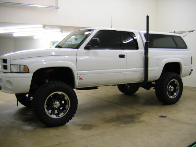
Better Headlights for your 2nd Gen Dodge Ram Truck Parts Needed:: Morimoto Projector Kit ( ensure you get the 9004 kit with the High beam controller AKA Motocontrol and the longer thread reflector) Clear lense housings ( not required, but way better output, ensure housings are aimable.) Flat head Screw driver Phillips Screw Driver T15 torx screw driver 10mm socket extension / 10mm open ended wrench Oven Epoxy Why to upgrade to Bi-xenon Projectors It's no secret that 2nd Gen Dodge Ram Headligts are terrible from the factory. There are various things you can do to help, Britebox relay system, bulbs, sport conversion, and my least favorite.....HID's, or a Projector retrofit like this. While the retrofit is the most costly I believe that it is the best choice. No tonly do you get to upgrade to xenon bulbs, but you upgrade to projectors that were designed for the xenon bulb, which is key. I truly hate seeing guys throwing HID's into their halogen AKA oem housings and claiming that output is great for only $50. What they don't relize is that when you throw a differently configured bulb into a halogen housing you are going to scatter light. The key to not scattering light, AKA blinding oncoming traffic is ensuring that the reflector housing is engineered for the bulb that is in it. The distance of the filmate is key when it comes to how light reflects in the housing. As you can see here moving the filmate, or installing a different type of bulb throws everything off. This is why I always prefer that if you are going to run different lights that you ensure the housing is right for the bulb. since the Morimoto projectors are bulb for a xenon mini h1 bulb you don't have to worry about it. You can have your cake and eat it too. The Design of the Morimoto Mini H1 Projector headlights You can see from the above that the Shield, or Cutoff Plate ensures that the light is reflected and projected in a manner than doesn't blind people. The result of a sheild in the up position does this You can clearly see the cutoff and how it prevents oncoming traffic from being blinded. Here is a closer look at the Cutoff Shield To activate you High Beams the shield is pulled down allowing light to be projected without being cutoff. The result is Ok that is enough on why I choose the Morimoto Mini H1 Bixenon projectors as the new headlights for my 2nd Gen Dodge Ram. Break Down of the Projectors This is most of the hardware you will get with your kit. The nice thing about the Morimoto kit is it allows you to install the projectors into the OEM bulb socket. This allows you to retain the OEM aiming ablility. the only hole you will need to drill is for the High Beam wiring. Sport Housings I decided to jump to sport lights in the middle of this process. These are the lights I got from Ebay. I am VERY happy with them. Amazon Sport Headlight Housings Link PN: 55077025ac 55077025AG They required a little cutting to get the projectors set in them, but nothing bad. You can get extended threads projectors so I would suggest that. Removing your housings to remove your Stock 2nd Gen Dodge Ram Headlights you will need a 10mm socket and an extension. There are 3 bolts holding the light in. Remove the 3 10mm bolts holding the light in (Red dots in picture). The lower inner bolt is somewhat hard to get to. I found that going from under the truck was easiest. Next pull the light straight back to pull it out of the push fittings. You should feel it "pop" out 3 or 4 inches. Next remove your blinker bulbs and disconnect the headlight bulb. Next remove the housing by sliding them towards the outside of the truck, twisting somwhat to free the housing. Take your time as this can be a stubborn part to get out. once you have both housings out you can go inside. Removing the headlight lens The easiest way I know of to get the lens off the housing is to use the oven. I set my ovens temp to 170*f and put the housings in for 30 minutes or so to heat the glue and make the lens easy to remove. Ensure you keep and eye on the housing while it is in the over. I have seen some ovens that are not accurate on heat and ended up melting the housing. Once your housings are to temp remove them and carefully use a flathead screw driver to pry the lens open. Move slowly around the lense and pry the lens off. you should feel it release, don't pry hard, if the glue isn't letting go put it back in the oven for another 10 minutes, increase temp if needed. Your end result should be like this It is key to notice that if you are using the OEM lenses that your output will be less than wonderful. you can see in the image above the Fluted design to help scatter the halogen bulb output. This however makes the cutoff line fuzzy. This is why a clear lens is worth having. Installing the Projector Remove all of your hardware from the projector so there is nothing on it. The threaded section should fit into the OEM bulb hole. Insert the projector into the housing from the front. Turn the housing over and insert the rubber washer, then the alighment washer, then the locknut. Tighten the lock nut down somewhat snug. Don't over tighten as you will have to level the projector by rotating the projector in the housing until the output is level. The housing back should look like this The Front will look like this Note the Red Dot. you will need to drill a small hole here to run the high beam wires though. Once you have your projector in the housing, install the Bulb holder onto the back of the projector, there are threaded holes for the small phillips screws. Install the bulb then the retaining clip. Installing the wiring The Morimoto Wiring Harness only requires connection to one of the 2 oem plugs. The wiring harness looks like this you need to make connection to the Battery + then a body ground on the end of each Ballast Output. The Input from the car plug will be a female socket 9004 connection. I choose to install the bulk of the harness on the Passengers side since I have more space over there. This system already draws power right form the battery so there is no need for a Bright Box type relay system. You will need mount the ballast's one on each side near the back of the light. I choose to the left and right of the radiator right above the light. Plug your ballast into the "Ballast output" plug from the harness. Leveling / Tuning your lights after everything is reinstalled into the housings you will need to put them into the truck and level the projectors. This needs to be done before you put the lense back on. Connect the bulbs to the wiring in the truck. Install the housings and install the bolts to ensure that hte housing is tight and won't move. You will need a large flat surface and level ground to do this. Park 20ish yards away from the wall on flat ground, turn the lights on. The truck will need to be running to trip the ballasts and ignite the bulbs. Once the bulbs are on you can kill the truck. Look at the output of the light once side at a time and level the cutoff line by rotating the projector in the housing slowly until you are happy with the level of the light You can see in this picture that the projector needs to be rotated slight clockwise. Once you are happy with the level of the cutoff remove the housing and tighten the locknut down. Be careful not to move the housing or projector. Repeat the process for both lights. Remember you are not aiming hte lights, only leveling the cutoff line. Ensure that the hole you drilled for the high beams is sealed with RTV or epoxy. Reinstall the lense Once you are happy with both sides use some epoxy to reattach the lenses to the housing. Ensure that it is a tight seal. Allow time for the epoxy to setup. Reinstalling housings and aiming headlights Reinstall the housings and install all bolts ensuring that the lights are held tight. Connect all lights and wiring to the housings. Now you will need ot aim your new lights. You will need the T20 torx to aim the lights. Park 25ish yards away from the large flat wall on level ground. Typical rule of thumb is you want your light hot spots to be directly in front of the bulb. Easiest way to ensure this is done is to pull close to the wall, aim the lights left and right until it is right in front of the bulb, then slowly reverse ensure that the hotspot does not move left or night as you backup. If the hotspot moves left or right adjust the housings to counter act this. Next you need to aim your lights up / down. Again rule of thumb is you want your hotspot at 25 yards to be 1- 4" lower than the level of your headlights. IE pointed down slightly. This will take some adjusthing. The cutoff lenses will keep you from needing to point your lights down very much. Depending on the height of your truck you might be able to get away with 1" of drop at 25 yards. The higher your truck is lifted the move drop your lights will need to keep from blinding people. This might take some trial and error. Drive around some, if peolle flash you drop your lights some until you are no longer flashed. In the end you should end up with lights that are much better than OEM. Your cutoff's should be straight and you should have a VERY wide beam. the ground is not level but you get the idea. this article should work for all 2nd gen Dodge Ram trucks 1994 , 1995, 1996, 1997, 1998, 1999. 2000, 2001, 2002.9 points
-
Quadzilla Custom Tuning How-To The Quadzilla Adrenaline allows for a significant amount of custom tuning to be done by the user to alter the way that the Quadzilla ADR commands fueling. This gives the Quadzilla a significant advantage over other tuners on the market. Looking to buy a Quadzilla here is the links back to Quadzilla Power. 1998.5 to 2000 Dodge Ram Quadzilla Adrenaline $699.99 2001 Dodge Ram Quadzilla Adrenaline $699.99 2002 Dodge Ram Quadzilla Adrenaline $699.99 Side note, if you would rather have a pre built tune to start with you can checkout our tune repository. https://mopar1973man.com/forum/182-quadzilla-v2-custom-tune-repository/ It is VERY important to understand that each truck is going to be a little different. Your truck will run as well as you tune it. We are more than willing to answer questions about how it works, but putting in the leg work is your responsiblity. If you follow the Guide posted in Section 3 you should have no trouble making a tune that works well for you. It is also VASTLY important to datalog while you are tuning. Compare smoke vs power to the data log to see where you need to add more fuel or pull more fuel. The Quadzilla V2 tuning is not magic, if you don't put time in to figure out what your truck likes the end result may be less than stellar. Please also consider if your truck has issues, apparent or hidden, with Sensors / Wiring / Computers the quadzilla platform will bring them to light and will likely not run right until the issues are sorted. YOU ALSO MUST HAVE AN IQUAD SETUP, PV1 and PV2 screens are too old and not supported! If you need to buy a Quadzilla Adrenaline you can order one here. https://www.dieselautopower.com/dodge-ram-cummins/1998-5-2002-5-9l-24-valve-dodge-cummins/chips-programmers-and-electronics-1 Use this Excel tool to let you build your tunes in Excel Download it and use it when building your tunes. Index: Section 1: Custom Tuning V2 Section 3: Getting Started with V2 Tuning Section 4: Example Custom Tunes based upon Injector Size Section 1: Custom Tuning V2 ******* It is important to Note that it is not recommended to stack ANY tuners when using the V2 tuning**** V2 of the custom tuning is the next level of custom tuning for the Quadzilla Adrenaline and the VP44 powered Cummins Power 2nd Gen truck. You must have a V2 base tune loaded for these to work along with selecting the V2 vehicle out of the Iquad Vehicle Selection list. One will not work without the other. All the above custom tuning is the same other than power levels and Can TPS Min and Max so I will not go over those again. V2 has everything that V1 has, but more. Can TPS min and Max are no longer used in V2 tuning as the user can tune CANbus fueling to their own liking above stock, below stock, or at stock levels. This makes TPS min and max no longer needed. ************************************************************************************************************************************************* Change to the Power Levels from V1 Tunes Quadzilla has introduced a new power level called power reduction as the new lvl 1. As a result, all V1 tuning levels are moved up one, Lvl 3, Canbus, has also been modified to allow for on the fly user based custom tuning. Lvls are now: lvl 0: Stock with boost fooling lvl 1: Power reduction for reducing power under stock lvl 2: Timing / MPG mode with Custom user Canbus for 0-10psi with a max of %100. Over 10 psi is possible, but only using the 10psi scaling % in the custom tuning with a max fueling of %100 of oem. lvl 3: Canbus Fueling + Timing including CANbus fueling scaling from 0 - 28 psi lvl 4 +: Wiretap + Canbus + Timing. The more levels you have the smaller the jump in power per level. If you have 7 levels, then lvl 4 will be %33 wiretap lvl 5 will be 66% wiretap and lvl 6 will be full wiretap. Because of the additional lvl we have increased the Max Level to 6 rather than 5 and the upper limit to 15 rather than 14. Lvl 1 now gives you a default of %50 power under the OEM tuning. This will allow pretty much ANY truck with ANY fueling mods to pass emissions that are based on smoke output, without making the truck dangerous on the road. Using Custom tuning you can set the OEM fueling to anything between 0 and 100% of stock. With 100 hp injectors setting this to %80 gives good power without smoke. These custom tuning settings can be switched on the fly without having to download a new tune. You can store up to 10 custom tunes on your device. Here you can see I have 3 tunes, Daily, Race, and Tow. Here is the screen shots for the new tuning. Max Power Levels Power Levels : You can set the minimize power levels to 5 or max to 14. This will give you more or less wiretap levels, Note that no additional power is made by setting max levels higher. Rather setting Max Power Levels higher give you more "steps" of wiretap fueling until the max is reached. IE: total power lvls = 5 gives you 2 wiretap levels (Remember to always could lvl 0 in your total lvls), so lvl 3 will give you %50 of wiretap stretch and lvl 4 will give you %100 of wiretap stretch whereas setting your max lvls to 14 will give you 12 steps of wiretap fueling lvl 3 would be 1/12th of wiretap stretch lvl 9 would be 7/12th of wiretap stretch and lvl 14 would be 12/12th of wiretap stretch Power Reduction: %0-100 gives the user the ability to fine tune how much power they want the truck to have based upon OEM fueling. Setting Power reduction to 0 will make the truck only idle Setting Power Reduction to %100 will make the truck run like stock. Depending on your fueling mods the truck is drivable from %40 to %100. A truck at 7000' altitude with 7 x .009 injectors will not smoke with this setting set to %75, the truck is still VERY street friendly. The emissions people will not question why the truck made only 100 hp as you can set the fueling reduction % based on your injectors to match stock power. Remember this setting is in the custom tuning menu so you can use multiple custom tunes for valet mode (%50) or Girlfriend / wife mode (%65) or emissions mode (%75) or anti-theft mode ( %0) **************************************************************************************************************************************************************** RPM LIMIT We have added a user defined RPM limit variable. you can set this between 3200 and 3700 rpm. Keep in Mind that max RPM will depend on the truck configuration. RPM Limit will put a limit on wiretap fueling. Canbus fueling is configured based on if the base tune is HardFuel or StandardFuel. Going over 3500 rpm should be done at your own risk. Weak pumps will likely not like being forced to rev beyond 3500. Hardfuel will try and extend canbus to 3500RPM StandardFuel will let fueling fall off at 3200RPM. **************************************************************************************************************************************************************** Timing Related Custom Tuning Max Load Timing Offset: 0*-3* setting that allows up to 3* of RPM timing to be based on load. This allows you to tune timing based on a bilinear calculation based on load and rpm. This setting does not increase your max timing, rather it puts weight on Load. IE: if your rpm was 2000 and your max timing for 2000 was set at 19*, your load timing was set at 3* and you are at %50 throttle, then you would get ~%50 of load timing ( 1.5*) which would put your current timing at 17.5* ( 19* max - 1.5* = 17.5*). Where as if you were at %100 throttle then you would get the full 19* of timing at 2000 RPM. Same example %30 load, would give you %30 of 3* = .9* so at 2000 rpm you would have 16.9* of timing if load was at 30% this new timing tuning will give you a significant amount of control over timing compared to other tuners on the market. Low PSI Timing Reduct We have added a new tuning variable to allow for the user to set a max amount of time to pull when TPS is high and boost is low. Pulling timing will assist in spooling the turbo. The range for this reduction is 0-5* Timing Reduction Scaling 0-%100 This allows you to set how much timing gets pulled from the Low PSI timing reduct number set. You may want more timing down low, but want to pull timing up top. Scaling function will limit max timing but allow for the map to calculate off of the max timing until that point is reached. IE: if timing reduction is set to 5* and scaling is set at %50 you will get a max reduction of 2.5* ( 5 * .50 = 2.5) but if the map calls from %50 you will get 2.5* at %50. It will effectively allow for you to reach your max sooner. the graph below so you how it works. Light Load Advance: This setting allows you to advance timing above the base timing curve if load is low. Timing advancement is based on load % where as %0 load would give you the most timing advance and as load increases timing will decrease. After 50 mph there is an additional 1* of timing added ontop of the configured value. Most setups should run a value of between .5 - 2.5 * of timing advance. Play around with this setting to see where EGT's are reduced at cruise state. Stock injector to ~7 x .009 - Generally speaking 17.5*-18.5* of timing is optimal for best MPG while at cruise at 55-65 mph. - Generally speaking 18.5*-19.5* of timing is optimal for best MPG while at cruise at 70-80 mph. - Tow tunes should use a cruise timing advance of .5- 1* unless studs are in place. - If you have Headstuds you can add more Light Throttle Timing for reaching the max MPG. *** ensure you don't overtime the engine in light load situtations. It is not recommend to go above 19* timing below 2k rpm at high load unless you have headstuds. set your base rpm curve responsibly so that at %100 load and WOT your timing is not dangerous. Light Throttle Load Limit: This setting it to set the high load limit for light throttle timing advance. Typically this will be set between 2-30% engine load. Once this limit is reached the Quadzilla will not use Light throttle timing, and only use fuel load and TPS reduction together to alter the base timing curve defined in the "rpm Timing Max" settings. RPM Timing Max Users are given 5 timing settings to set max timing at, It is VERY helpful to data log OEM timing to get a grasp of what your truck is "safe" to run. Leave the Quadzilla on Lvl 0 and do a run with various driving styles. Make note of timing at 1500 rpm, 2k, 2.5k etc. 1500 rpm: Typically users will want to keep this between ~13*-16* ** Keep in mind that OEM timing is referenced for sub 1500 rpm timing. You might see timing above or below your 1500 setting at light throttle. 2000 rpm: Typically users will want to keep this between ~16*-20* 2500 rpm: Typically users will want to keep this between ~20*-25* ** please consider the risks of running high timing, Typically stock tuning allows for up to ~26* at 3k rpm. There are benifits to going higher, like reduced EGT's but be aware of the risk. If you are running studs then the risk is nominal. Most other timing boxes on the market will max timing if boost is up after ~2500 rpm 3000 rpm: Typically users will want to keep this between ~25*-30* ** if you want upper end power then setting your 3k to 30* to max timing will help. Consider the risks involved with extreme tunes Max: Typically users will want to keep this between ~26*-30* ** please note that setting timing higher than suggested may lead to headgasket issues, please ensure you have supporting mods, IE studs, before venturing outside of the recommendation. ************************************************************************************************************************************************ Boost Related Custom Tuning CanBus Custom Tuning In the Custom tuning menu, there are an addition 25 new Custom tuning variables that allow you to set a % of power level above or below stock. The range for this is %50 - %150 You will need to configure this for each psi leading up to 30psi. From 0-16psi is a % per psi above 16 psi is % for 2 psi. It is possible to tune any truck with any injectors to be very clean. Typically ~%70 is the lowest usable % and %130 is the highest, but this will differ from truck to truck. Trucks with VERY large injectors may have a Canbus curve that is below %100 for the entire curve. Truck with near stock sized injectors will typically set this number above 100% increasing as the PSI increases, trucks with large injectors can set low PSI scaling under %100 to clean up off boost fueling. You will notice some increase in lag due to this, but you are able to make fine adjustments to get power where you want it throughout the power range. The best fueling curve will typically be the smoothest curve to reach full fueling when at WOT. using %112 will max out fueling on the upper end. The bigger your injetors as the more gental you want you curve. THIS WILL TAKE SOME FINE TUNING ON YOUR PART FOR BEST RESULTS. MAKE %1 CHANGES ON EACH PSI LEVEL. IN MOST CASES YOU SHOULD NOT MAKE A JUMP OF MORE THAN %5 GOING FROM PSI TO PSI. THE HIGHER THE JUMP IN % THE MORE AGGRESSIVE THE QUADZILLA WILL RAMP UP FUELING. If you want V1 like tuning and you have stockish injectors add 110 to the PSI level you are editing. IE: 0 psi = 110% 5psi = 115% 10psi= 120% _________________________________________ Wiretap Tuning Max Pump Stretch: sets the upper limit for Wiretap Fueling time. Typically 2200 is the max on the aggressive tunes. This is what allows for the calculation of how much pump fueling to use. Remember that you are setting the max amount of fueling. This fueling time is altered by many different inputs such as, but not limited to, boost, rpm, APPS, etc on v1 base tunes lvls 3 - max divide the max stretch by the span IE: if you have 10 levels total 4-10 are wiretap so you have 7 lvls of wiretap on lvl 4 you get 1/7th of additional wiretap fueling, lvl 5 you get 2/7th and so forth. Setting Max Pump Stretch higher may reduce total power while increasing Torque under the curve. If you want upper-end power you would not want to set this to the max. If you want low-end torque you would set this higher. Typically people find that 1600-2000 is the happy spot depending on your injector size and driving style. Smoke output will be increased by setting Stretch higher. TPS scaling functions: By watching TPS / APPS input from the driver the Quadzilla can adjust the fueling curves for Wiretap fueling. This is helpful to tune the Quadzilla to your driving style and can help cut down on low end smoke. TPS Pump Max: This allows for you to set the upper limit for TPS input for wiretap fueling. Wiretap fueling does not stop at this point, rather it peaks at this point. Using the max and min settings you can move the wiretap fueling area around within the 0-100% TPS range. TPS Pump Min: This allows for you to set the lower limit for TPS input for wiretap fueling. Wiretap fueling will not start until this point is reached. Using the max and min settings you can move the wiretap fueling area around within the 0-100% TPS range. Effectively by settings the max and min you are compressing %100 of the fueling between the max's and Mins. IE: maxs at 75 and min's at 25, or cutting the tps range to %50. You will effective double the fueling ramp up once %25 tps is reach until %75 TPS is reached. At %75 TPS input fueling will max out until %100. No additional Power is made, rather the unit can tailor itself to your driving style. This can be used to help low-end spool or help with City driving to keep power down. If you set the min above your typical DD TPS input you can disable fueling when you don't need it. Minimum Pump Tap Fueling Percentage: 0-50% This Tuning variable is to set a low limit % for wiretap. Caution should be used when setting this setting in your custom tune. If you set it at %25 you will get no less than %25 of wiretap at any point in the map at WOT. Setting this high will make the truck smoke, but can be useful when creating a Race tune. Normal DD tunes should likely use %5 or less. Smoke free tunes should use %0. Pump Low boost Scale PSI: 0-25 psi This set the low limit for the wiretap fueling map. If you set this at 0 your wiretap will begin at 0psi. If you set this at 15 your wiretap map will start at 15 psi. Set this variable to whatever PSI you want Wiretap to begin fueling. ** Please note that Boost Scaling V1 tuning cannot set lower than this setting., The ADR will add 5 psi to the v1 Boost Scaling if you set them the same. Boost Scaling: 20-40 psi Allows you to set the point at which fueling is maximized based upon boost levels. Setting this to 20 will give you fuel fueling at 20psi, assuming tps min / and maxes are met. Boost scaling is calculated along with TPS scaling so in order to have %100 of fueling both need to be met. This setting defines the Y axis of the wiretap map, 20 psi means your map range is 0-20 psi 40 psi means the map is 0-40 psi. Keep in mind that your pump low boost scale PSI setting defines what "0psi" is. IE if pump low boost scale is set to 5psi and your boost scaling is set to 20 psi, then the wiretap map will be 5-25 psi. **************************************************************************************************************************************************************** These new custom tuning features are in addition to the V1 custom tuning, so if your TPS is set high that you are currently at you will not have fueling. All custom tuning mins must be reached for any fueling to happen. This Video covers the above tuning Section 2: Getting Started with Quadzilla Adrenaline V2 Custom Tuning ***************************************************************************************************************************************************************** if you would rather have a pre built tune to start with you can checkout our tune repository. we have lots of tunes that cover various configurations https://mopar1973man.com/forum/182-quadzilla-v2-custom-tune-repository/ When you are starting to use V2 Tune on your truck you should follow these steps. 1. Find your starting % 2. Set your base map 3. Fine tune your base map 4. Set your Wiretap start point 5. Set your Wiretap Fueling % This tuning should not be done on busy roads or in any place that risk of crashing or hurting others. A back country road is recommended. Save your tune after EVERY change. Don't forget you are able to create more than one custom tune so you can setup a race tune or tow tune or DD tune. Tune your custom tunes with something in mind. Don't try to make the truck do everything on one tune. Step 1. If you have stock injectors you can set this to 100% or above so you can skip this step and move to Step 2. Use LVL1 and the Power reduction % to find a good point for the CANbus fueling %. For 50 hp injectors start at %95 and move up or down by %1 depending on if you get smoke when you snap throttle from 0-%50 while in gear. Find a reasonable % for smoke output vs low-end power. Remember this is to handle off idle power. ENSURE WHEN YOU ARE TESTING YOUR STARTING POINT YOU GO %100 THROTTLE INPut. You want to set your smoke level as WOT. This will give you the most resolution in your throttle movement. IE: if you truck maxes out fueling at %30 throttle, what's the point of the other %70 of throttle movement. Make %100 fuel %100 throttle. Good starting points per injector size ***use only as a guide you will need to go through some trial and error. 50 hp injectors %95 100 hp injectors %90 150 hp injectors %85 200 hp injectors %80 250 hp injectors %75 300 hp injectors %70 Once you have found a good starting point Set your 0 PSI % to this power reduction % and set your Power Reduction scale to a % that you want to allow for a valet mode or antitheft or emissions or whatever for reduced power. Step 2. Set Quad to Power LVL3 Once you have a good starting point defined for 0 psi scaling increase every % by 1 as you move up in psi. As you hit 10-15 psi you can move up by 2 or 3 % per psi until you max out at ~%130. You will notice that the Canbus HP limit is somewhere around %130 depending on the truck and the mods. This should give you a good base fueling map to fine tune your truck by. Step 3. Once you have your base map do some 0-%50 APPS take off's on LVL3 only. Pay attention to Boost numbers and smoke output. a video camera is very helpful. ENSURE YOU ARE NOT AROUND OTHER DRIVERS OR PEOPLE WHEN DOING THIS!!!!!! You may notice puffs of smoke as PSI climbs, reduce the % at that psi point by 1 if smoke is too much. If the truck feels laggy at a given PSI increase by %1 until your truck feels good. Keep in mind that smoke from the tailpipe may cause flooding of the turbo. A truck will respond best when there is a slight haze under high throttle input. Don't be afraid to use high TPS input to get the truck moving. That is what the throttle pedal is for! Tweak your 0-30 settings until you are happy with how the truck drives on LVL3 Step 4. Once you have your CANbus tuning done move to wiretap tuning. Wiretap fueling will increase power significantly when it is used. Depending on your wants you can set low limit fueling for wiretap. This will allow for smoke reduction when wiretap comes on. Set your low limit for a PSI that is above your normal DD / cruising PSI. IE if you drive to work every day and don't normally hit 10 psi set your low limit above 10 psi. If you want wiretap fueling when you typically drive set the low limit below that. I would not recommend setting this below 5psi as smoke control is much harder. Remember low limit allows for wiretap scaling below that point. TPS min also comes into play so set your pump TPS min at a point that makes sense for your driving style / needs Step 5. Timing tuning is a little tricky and should not be taken lightly. I suggest that you keep your timing tuning configured as 1500 max: 14* 2000 max: 18* 2500 max: 22* 3000 max: 25* max: 26* UNLESS you have time to do a good amount of data logging and figure out what is best for your truck. Keep in mind that aggressive timing can cause issues. The above should be considered very safe on pretty much any truck. OEM timing will hit 26* in stock form. What you will find however is under the curve power will be improved by adjusting these settings. Step 6. Once you have set your low limit for Wiretap fueling set your scaling. This scaling will set how much wiretap fueling is added before the low limit is reached. If you want no wiretap before the low limit set this to %0, if you want half set this to %50 and so forth. Typically I leave this between %15 and %25 depending on how aggressive you want the truck to feel when DD'ing the truck. Setting this % higher will increase smoke output off idle. ******************************************************************************************************************************************************** Section 3: Custom Tunes based upon Injector size Visit this thread for a list of Users custom tunes. https://mopar1973man.com/topic/12002-quadzilla-v2-custom-tunes/ This has some pre built tunes for various setups and needs https://mopar1973man.com/forum/185-standard-quadzilla-adrenaline-tunes/ Here are videos showing before and after the V2 tuning If you find this helpful throw a donation my way. %95 of the things I do in regards to Quadzilla are to support the community and I receive no payment for the work. Thanks - Me78569 ]9 points
-
The Full Parts list can be seen below, or you can use the links to filter to the section needed. You can find any PN needed for a Late 2nd Gen Dodge Ram Cummins Powered Truck. A lot of parts are shared between the year, but please ensure you check that the part works for your year if we don't have a PDF for your specific truck. Diagrams are in place for each section. some of the main categories are featured in the drop down menu. These should all be Dodge specific Part Numbers. Exterior & Panels Go To Mopar Accessories Go To Frame & Bumper Go To Exterior Panels Go To Emblems Go To Exterior Doors This should work for all late 2nd Gen Dodge Ram Trucks, 2500 and 3500 for 2001, 2002. VP44 Cummins Part Numbers included.9 points
-
Torque Converter Lockup Switch with Brake Pedal Release System What it will do This system can keep the torque converter locked in 3ed or 4th gear. With a modification to the valve body 2ed gear can be locked up. When driving normal freeway speed the torque converter can be locked up with the momentary switch and stays locked up. The transmission stays in direct drive even when the accelerator pedal is released, there is no freewheeling, RPM level is maintained and torque converter unlock is done with either pushing the momentary switch again or pressing the brake pedal. When going up long grades select 3ed gear, overdrive locked out, then lockup the torque converter with the momentary switch. I have found that by doing this I see very little rise in the transmission temperature with a decrease in exhaust temperature of 200o F. Unlocking the torque converter is done again by pressing the momentary switch or brake pedal. The trans mission will up shift from 3ed to 4th but will not down shift from 4th to 3ed with the torque converter locked. When go down a long or steep down grade the locked up torque converter will help in slowing but without the added benefit of an exhaust brake. Another switch* is incorporated in the system which will lock up the torque converter and stepping on the brake pedal will not disengage the lock up. How it works The system uses three switches, two relays and a light. The first is the momentary switch. This switch is used to signal the transistor in the switching relay to either power the coil and close the contacts allowing power to flow between pins 15 and 87 or stop the power to the coil and open the contacts. The brake light switch is three switches in one: brake lights, cruise control and anti-lock brake system. The anti-lock brake system grounds through this switch, white/pink wire, and is closed circuit until the brake pedal is depressed making it perfect for grounding terminal 85 of the switching relay. When the transistor loses its ground it turns off the power to the coil and the contacts between pins 15 and 87 open stopping current flow to the grounding relay. The 3ed switch* can either be floor mounted or dash mounted. This switch is used to energize the grounding relay and light. This keeps the torque converter locked when using the brakes. I use a floor mounted head light dimmer switch to turn it on and off. The switching relay is used to control the power to the grounding relay coil with the use of the momentary and brake light switch. This relay is used in 1981-1988 Volvo models 240 and 740 that had 5 speed manual transmissions with the overdrive 5th gear is a Laycock overdrive unit and provided power to the hydraulic solenoid. The grounding relay is used to open and close the circuit that grounds the torque convertor solenoid via the orange/black wire at PCM connector B11. Since this relay is used as only a grounding switch its power rating can be minimal. There is a light add to the system that is on anytime there is power supplied to the grounding relay and the torque converter is locked up. I used a green LED light so that the color isn’t annoying and power usage is low. Parts needed 1 overdrive relay for a Volvo manual 4 speed w/od (M46) IPD.com part# 102250 1 Bosch type/mini ISO relay terminal 87 normally open (NO) 1 12V LED light, Linrose Superbright LED Frys.com part# B2191L5 1 push button momentary switch, Phillmor Push Button green Frys.com part# 30-12634 E-Bay 1 headlight dimmer switch O’Rielly.com part # DS109 1 ½ watt 33ohm resistor NTE HW033 Frys.com part# 999026 1 fuse holder with 1-2 amp fuse 6 Scotch Lock connectors 2 #8 X 1½” self-taping sheet metal screws Solder Heat shrink tubing 1 central lock motor harness from a 1981-1993 Volvo model 240. The wire harness is found behind the center of dash. 1 overdrive relay harness from a 1982-1993 Volvo model 240 with either manual or automatic transmission. The wire harness is found above left front kick panel for manual trans or behind right center of dash for automatic trans. 1 shift lever from a 1998-2002 Dodge Ram 1500, 2500, 3500, Dakota or Durango. If you’re making the wire harness 11 solderless insulated female spade connectors .25” sized for wire gauge 3-4 solderless ring terminals sized for wire gauge and grounding screws. 18-20 AGW stranded (16 AGW will work if you can’t find smaller) in different colors. Try Home Depot or Lowes electrical department. Putting it all together Study the wiring diagram and have all of the parts in hand before starting the installation. Most of the wire length is from 6” to 2’. The wires for the light and the floor switch will be 4-5’ depending on where you put them. The wire from the grounding relay to the PCM will be about 8’. The power lead with fuse can be attached to any wire that is hot when the key is turned to the “on” position. The power draw should be between 1 and 2 amps; with the system having its own fuse, there should be no problems. Install the ½ watt 33 ohm resister between pin #87 of the grounding relay and ground by cutting the wire and soldering the resistor in place. I used the wire harnesses and relays from old Volvos that were in a wrecking yard. I modified the wire harness and added extra wire for the longer runs. An extra shift lever can be obtained at the wrecking yard for a few dollars also. Installing the momentary switch: refer to article written by Me78569 DIY- Lockup Switch install into Gear Selector Arm. This is a great how-to article on installing a momentary switch in the gear selector. If putting the switch in the gear selector arm is a bit difficult then try installing it on the steering column cove or some were on the dash board bezel that’s easily reached. You will need to remove the panel below the steering column, the dash bezel and the head light switch for the relay installation and wire routing. The left A post cover will need to be removed if the light is going to be installed there. Take your time and identify what wires are going where, think two or three times before cutting any wire. You should not have to cut any of the truck factory wires. The only wires that need to be cut are the ones you are adding. Find where you want to put the relays and LED light. I put my relays behind the bottom panel under the steering column and worked out from there. I have my LED light mounted next to my transmission temperature gauge. It’s at eye level and I just have to glance at it to see if the torque converter is locked or not. The light on JAG1’s truck was installed in the dashboard bezel between the headlights switch and instrument cluster. You will need to drill a hole through the plastic then slide the light housing into the hole and secure it with the supplied clip. Once the light is secured the wires can be connected and the bezel refitted. The 3ed switch* for energizing the grounding relay is mounted on the floor left and forward of the brake pedal in about the same spot the headlight dimmer switch was located back-in-the-day. I mounted this by putting the switch on top of the carpet and drilling through the floor pan with the self-taping sheet metal screws. A toggle or push button on/off switch could be used and installed on the dash bezel if the floor mounted switch is not to your liking. * Caution: coming to a full stop with the torque converter locked will stall the engine and could cause damage to the flex plate, input shaft or other driveline parts. Prepared by: J. Daniel Martin / Martin’s Mobile Maintenance AKA: IBMobile 11/12/20179 points
-
8 points
-
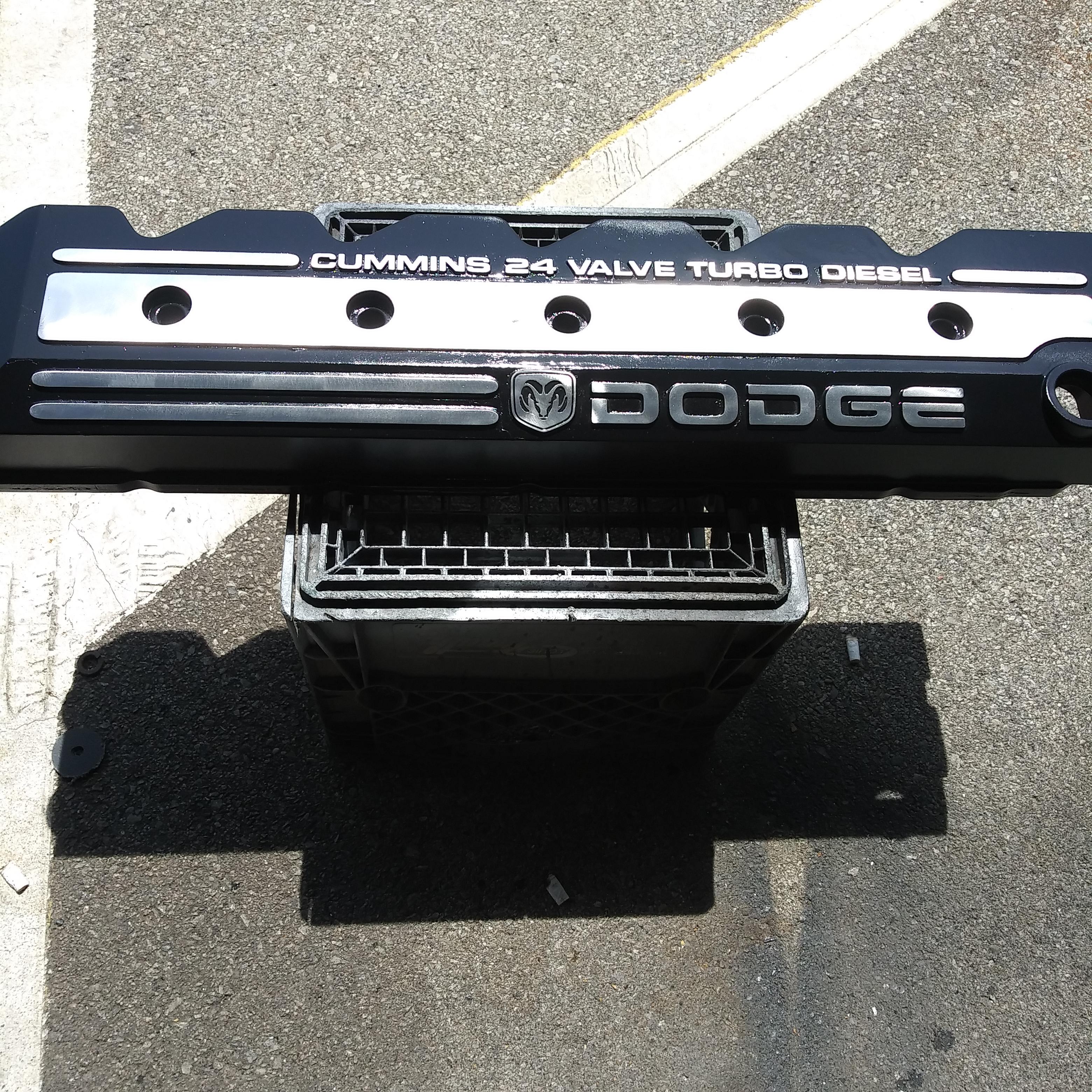
8 pointsCrankcase Vent Modification for 24V Dodge Cummins Trucks People been asking for me to redo this article so here it is. Supplies you'll need... 1 stick of 1/2" PVC pipe (minimum of 57" long) 3 - 1/2" PVC elbows slip to slip 1 - 1/2" PVC elbow slip to NPT (male or female) 1 - 1/2" PVC straight connector slip to NPT (male or female) 3" piece of 3/4" heater hose 2 hose clamps 1 Small can of PVC glue Hacksaw Sharpie black marker Tape measure Can of spray paint 1 Zip tie 6" long Cut measurements 3" Heater hose 4 1/2" front down pipe 2 1/4" front cross pipe 24" long pipe 5" rear cross pipe 20 1/2" rear down pipe NOTE: These measure are my final cut measurements. I suggest cutting a tad long and adjusting as you see fit for your truck. So at this point you should have all your materials to assemble. You should assembly your cut pipe and fittings dry without glue and test fit everything. While test fitting be sure to remove all plastic cuttings from the ends of the pipes. Also when test fitting be sure to bottom out all pipes into the fittings. In the supply list I list PVC elbow and a straight connector (male or female) this is totally up to you. You can do either way as long as you have a male and female connection in the end. Now during my test fitting I was very careful to get the front section of pie back far enough so its not in contact with the upper radiator hose. On the rear section you have to be careful of the angle of your down pipe. I've got mine resting on the very tip of the bellhousing. Now that you fairly happy with your fit. Take a Sharpie marker and mark all the elbow positions with a fine line from the elbow to the pipe to note position. This way you can glue the pieces back together in the proper angles. When gluing all the pieces together be sure once again to bottom out all your pipes into the fittings. At this point you will want to stuff your 3" piece of heater hose on the front pipe. Need at least 1" of heater hose on the PVC pipe for clamping. Now take a rag and a bit of paint thinner or lacquer thinner and wipe all the oil and grime off the pipe assembly. Now take a can of spray paint of the wanted color. It's best to get a spray paint that is chemically correct for plastics. So you should have a completed Crankcase vent pipe for your truck now. All you have to do is lay it back up on top. Make sure you have your 2 hose clamps on before installing. Slip the heater hose over the crankcase vent nipple. Using the one zip tie tie the rear cross pipe to the top of the hoist ring. Carefully slide the down pipe down and screw on to the rear fitting. Opps. the Paint was completely cured.8 points
-
8 pointsIf you own a 94-97 Ram 2500/3500 4x4 then your probably aware of the steering related issues these trucks can have, most notably the dreaded “death wobble” and steering wander. You may have replaced all the ball joints, tie rod ends, track bar, and even the control arm bushings on your truck but still have wandering or death wobble issues. Before you set your truck on fire and/or pull your hair out, you may want to consider upgrading from the factory Y style steering to the later T style. How will converting from an inverted Y setup to a T setup improve the steering you may ask? It's simple really. Notice that the tie rod on the light duty inverted Y steering (94-97) does not directly connect both wheels together. Instead it connects to the drag link which is then connected to the knuckle. This setup allows the tie rod to pivot as the axle moves up and down during normal suspension travel, which is exaggerated even more when traveling down very bumpy roads. The problem is that as the tie rod pivots it also changes the toe-in/toe-out of the alignment, which in turn causes the front end to “walk around” or “wander”. This design can also cause death wobble, even when all new parts are installed. The heavy duty T style steering eliminates the pivot point by utilizing a one-piece tie rod which is unaffected by suspension movement. If you do a Google search on the subject you're likely to come across numerous discussions of using the T style steering from a 4th Gen Ram for the conversion. The problem here is that the tapered holes in the knuckles will have to be enlarged in order for the 4th Gen parts to fit. As a note you can't simply drill out the tapered holes, they require a larger diameter TAPERED hole and NOT a straight diameter hole. So, besides dropping big money on a custom steering setup what other options do you have? Why converting to the 98-99 HD steering of course! 98-99 Ram 2500/3500 trucks came with either the light duty inverted Y steering or the optional heavy duty T steering. The drawing below shows the 94-97 light duty inverted Y steering and the 98-99 heavy duty T steering. The HD steering option was only available for the 98-99 model trucks. One of the best parts of this conversion is that it is a direct bolt-on for the 94-97 trucks. However, there is one catch, in order to retain the steering dampener you will need a universal style bolt-on mount. I currently do not have a dampener installed and to be honest I really don't feel the need to use one with this steering. Here are the parts you will need for the conversion. All part numbers are AC Delco Professional. These AC Delco Pro parts are actually re-branded Raybestos Pro parts. AC Delco Pro parts are easier to locate than Raybestos, which is I why I used them. To complicate things a bit more, these same parts are offered by NAPA under their own name for about 60% more than AC Delco Pro from RockAuto. CarQuest offers these parts under Raybestos Pro and are also about 60% higher than RockAuto. They are also available in Moog. PN: 45A3074 Inner TieRod Rockauto Link PN: 45A6011 Small Collar RockAuto Link PN: 45A0811 TieRod End RockAuto Link PN: 45A3073 Passenger Side Tierod RockAuto Link PN: 45A6058 Large Collar amazon Link PN: 45A0871 Drivers Side TieRod RockAuto link You can do this conversion with the truck on the ground, in fact it makes keeping the alignment correct easier. Start off by making sure you're parked on level ground, wheels pointed straight ahead and the steering wheel straight. It would also be a good idea to chock the wheels as an added safety precaution. NOTE: I had the passenger side knuckle apart because I was replacing the ball joints when this picture was taken. This is NOT required for the steering conversion so please disregard. First step is to remove the steering dampener bolts located at the arrows along with the dampener. The frame side bolt head is 15mm and the nut 18mm. The drag link side nut is 18mm. Using needle nose pliers; remove the cotter pins from the driver, passenger, and pitman arm rod ends. Once the cotter pins are out, remove the nuts. Passenger and pitman arm nuts are 21mm, driver side is 22mm. This image shows a pitman arm puller installed. It's a straight forward tool to use, just tighten down on the bolt head until the rod end pops out. I was unable to use this puller as it was damaged while removing a stubborn pitman arm. This image shows a pickle fork being used. You wedge it flat side down in between the knuckle and rod end, then drive it in with a large hammer. The process is the same for the pitman arm rod end as well. A pickle fork works great for removing rod ends that will not be reused. You do NOT want to use them on rod ends that WILL be reused as they tend to destroy the rubber grease boots. With all three rod ends popped free, remove the old steering assembly from the truck. Below is a comparison shot of the old inverted Y steering to the 98-99 HD T steering. The old tie rod measures out to 1.000” while the new one is 1.250”. Both drag links measure out the same at 1.125”. Assembling the new steering is pretty self explanatory by looking at the above picture. One thing worth noting is that when assembling the new steering, make sure that there is an equal amount of thread showing between the rod ends as shown below. There is an alignment bar (red arrow) attached to the old drag link that needs to be removed and installed on the new piece. Loosen the 15mm alignment bar nut and slide it forward out of the way of the adjuster sleeve. Loosen the first adjuster sleeve screw, leaving the other tight. Unscrew the adjuster sleeve and short rod end together and remove them. Tap the alignment bar off of the old drag link and install it on the new one as shown below. Screw the new adjuster sleeve and rod end on and you're almost ready to install everything. This would be a good time to install the grease zerks. The tie rod end zerks are 8mm and the drag link ends are 7mm. Now you're going to adjust the tie rod adjuster sleeve until the tie rod fits into the knuckles WITHOUT moving the tires. Moving the tires will throw your alignment off which is what you're trying to avoid. Once the tie rod is bolted on, install the new supplied cotter pins. Next you're going to loosely mount the drag link to the pitman arm being careful not to move it. Then adjust the drag link adjuster sleeve until the drag link reaches the mounting hole in the tie rod, again being careful not to move anything. You do NOT want your tires OR pitman arm to move. If either move, it will throw off your steering wheel alignment. Once the drag link is tightened up at both the pitman arm AND tie rod mounting points, install the new supplied cotter pins. Here's everything all bolted up. I'm not running a steering dampener but they are easy enough to install if you so desire. All that is needed is a universal mounting kit and a new dampener. You can also weld on some mounting tabs as well. A couple notes: Even though you were careful to not move anything during the install you will still more than likely need to fine tune your alignment and steering wheel center. My alignment was darn close but my steering wheel was about a ¼ turn off. I wasn't done centering my steering wheel yet when the picture was taken so the alignment bar was still slid down out of the way of the adjuster sleeve.8 points
-
I have been feeling the need to do a write up on this for sometime now. The more and more I learn about how tuners work for our trucks the more I feel like there is a serious amount of misinformation out there that REALLY needs to be corrected. What you guys pay your hard earned money for should return results beyond what some guy's distance friend thinks is awesome. This is not meant to explain the deep in's and outs, rather a rough idea of how things work and why some setups are good and others are not. First let me explain how our trucks work on a basic level when you push the pedal down. IE: How does the VP44 know when and how to fuel? Info taken from vp44 CAN message - Dodge Diesel - Diesel Truck Resource Forums thanks to Jdonoghue and his work from ~ a decade ago. When I say there is nothing new in terms of magic inside the ecm or vp44 I mean it. Next lets look at what type of tuners we have for our Vp44 trucks and how they work on a basic level. 2. Canbus Tuners: Edge EZ Quadzilla ZXT, ts mvp, anything that plugs in under the hood to the data port. 3. Wiretap only tuners: TST comp might be more not sure haha. 4.Wiretap and canbus tuners: Edge Comp / juice, Quadzilla Adrenaline, redline. Lets remember that canbus fueling actually makes up the vast majority of fueling / power in our trucks. Wiretap adds a good amount of power, but not nearly as much as canbus fuel. On a stock truck canbus fuel alone will get you to 300 hp wiretap will only bring that up to ~420 hp according to ricer math on the hottest tuners. so ~75% of the power is actually coming from Canbus alone and wiretap adds another ~%25 on top. 300 hp is approx %75 of 420 hp. So now that we have a basic understanding of tuners lets look at stacks and what they do. Throughout this I am going to reference the Throttle pedal as if it was a volumn knob on a stereo. 0 = silent / engine off 10 being WOT or stereo as loud as it will go. Let me start off by saying that there are good reasons to stack in some situtations. In my opinion you should never stack programmers that do the same thing. It is commonly accepted that you shouldn't stack 2 boxes that do timing. The thought with Stacking Timing boxes is it over advances timing causing issues. Generally unsafe I suppose. Not sure if I believe that fully, but regardless your truck will run like garbage, and you feel that in the butt dyno. We all agree it's not a good idea. Oh the Butt dyno....we'll get to that in a second. But people seem to ignore the same thought process for canbus fueling. You ask ANY tuner and they would tell you that too much fuel is a bad thing for performance. We all know that "flooding" the turbo results in poor performance. So why is that the same mindset does not apply to the fueling side of tuning in the same way as the timing? Reason that no one seems to care is that there is inheriently no high risk of damage and the Butt Dyno says it works. Kinda like the facebook, if someone says it's ok on facebook then we are all good. So the masses tend to ignore overfueling as being bad. So the Butt Dyno, So back on topic. Stacking, So if we think about our 0 - 4095 fueling message as being directly related to 0-10 on our volume knob on the stereo ( obviously in the real world it isn't linear, but in this example it is). So loudness on canbus is 0-10. So here we have a data log from a normal DD drive on OEM fueling on the "canin" column, you can see that in stock form once you are moving you normally see a canbus message of above 1000. So you range for fueling if you want to get going is no longer 0 - 3600, rather ~1000-3600 which makes sense it takes power to move the truck down the road. So in Stock form our volume knob has a range of 2.5-8. 2.5 = 1000 and 8 being 3600 or stock tuning max Whats important to note is that our volume knob is stuck going no lower than 2.5 when you step on the pedal to catch the mustang in front of you. So our knobs 0 position is now 2.5 as the truck needs to move down the road. So what happens when we add one tuner say smarty on top of OEM? Say the tuner addes %20 fuel down low, great we all love power.... Our low limit is already 2.5, but we added ~%20 up top also. cool now our knob goes up to 10. Awesome news! So what happens if we stack 2 boxes that do Canbus Fueling? So down low the Smarty tuning in the ECM is asking for %20 over stock when you hit the skinny pedal. then the canbus piggy back box is intercepting that fueling command of (OEM + %20) and adding it's own fuel on top. So we end up with (OEM + %20) + %20 as the lowest amount of fuel we get when we want to pass someone. The stack doesn't give us more top end due to the limited size of the fueling message IE: 10 on our stereo. So our range of fueling is now %50 min and still %100 max, so our stereo only works between 5 and 10. So our volume knob's 0 is now 5. Not exactly what I would call a good setup. so here's a visual idea of what I mean. You can see how the stacked setup just maxes out fueling sooner, Kepe in mind our trucks fueling is in no way linear, but you can see how stacking just causes overfueling. Report this image Most stock guys won't really see this as an issue, but what you need to see is that your throttle movement is limited to %50 of what it used to be. Same max power, it's just all moved between 0 and %50 throttle position durning DD driving. Anything over %50 is reaching that max fueling message size of 4095. so if you go to %60 you truck is just as fast as it was at %50 throttle and so forth. It is easy to see that you are just maxing out fueling sooner and sooner with less and less throttle travel IE less and less control over your truck. Stacking tuners is like only being able to control your volume on your stereo between 5 and 10. You'd be pissed if your radio never went below 5, why do you want your truck to drive the same way? Solution Time More control is a good thing. It's a brave new world, tune your truck correctly and use the throttle if you want power. So when should you stack? It's easy....Only stack things that do different things. You only need 1 box that does each thing, canbus fueling ( from the ecm or piggy back) + timing + wiretap( if you want it). The only thing you gain by stacking boxes that do the same things is a lighter wallet. You get no more power at the cost of less control over your truck.8 points
-
HE351ve Holset VGT Controller This article is for the standalone controller / tuner needed to control a Holset HE351 ve He351 VGT turbo from a 6.7 Cummins. This controller will help you tune the holset he351ve vgt turbo for your truck. It is is %100 open source you can tune the turbo in any manner you like. It will take some trial and error to tune the holet he351vgt, but the pay off is worth it. The he351ve really shines when it comes to low end power and having a flat torque curve. He351ve Airflow Specs The reason for wanting this turbo comparted to another aftermarket turbo are, Increased flow over a hx35 turbo ( 60lb/min to 69 lb/min) built in Exhaust Brake functions, Cheap turbo cost, fast spooling, and good mpg's if you have it tuned right. For a 5.9 Cummins the he351ve makes a great towing turbo for hp levels up to 500. It will be hot at 500hp but it is possible, not recommended, but possible. This should also work for He451 ve vgt or other Holset variable Geometery turbos. 551 431 turbos There is a certain amount of DIY needed to get this setup on your truck. You will need to learn the arduino system, how to wire it, power it, etc etc etc. Basic Video Here is a Video of the basic code and how it works with the VGT turbo If you read through this and have ANY questions, feel free to Post to the Ongoing thread covering the progress on this project You can Find the Forum Link HERE Parts: Here are the list of parts that are used. you can void the code to use one or all of the sensors, but this list is for everything. Arduino uno: http://www.amazon.com/Arduino-Board-Module-With-ATmega328P/dp/B008GRTSV6 $25 Canbus Shield: http://www.amazon.com/CAN-BUS-Shield-Compatible-Arduino-Seeeduino/dp/B00NQVH666 $40 Exhaust/boost sensor 0-100 psi: http://www.auberins....products_id=271x2 if you want to control the turbo on both exhaust and boost. $56 a piece and they come with 3 wire pigtails. Potentiometer push pull 10k linear: Mouser Link $15 Momentary on button switch: havent picked one up yet that I like. Currently using a computer button. Wire: 16 gauge should be fine 100' should be enough, ensure to get good quality wire Connectors: I used 2x DT06-12SA and 2 x DT06-12PA along with all hardware, ebay link LCD Screen: I used a 4x20 screen with a I2C adapter. Searching EBAY should find you one. Click link to see search. Turbo Connector 4 pin: Mouser Connector Link 54200410-B Pins 10762770 Turbo RPM Connector: Mouser Connector Link PN: 282087-1 Software: You will need to download the Arduino program: Arduino - Software You will need the libraries that I use. You can Download them all from My Google Drive Download the Canbus library: Dropbox - CANLibrarymaster.zip (thanks to Farm828) download the LCD Library: Dropbox - LiquidCrystal.zip Download the Freqmeasure library https://www.dropbox.com/s/yv98sgdllckc9z4/FreqMeasure.zip?dl=0 Download the Timer library https://www.dropbox.com/s/xa0lxny0pftdi6h/Timer-master.zip?dl=0 Basic starter Code downloaded here: Dropbox - HE351VE_Control.ino (thanks to Farm828) This is the code from CF without my changes You can edit the code by voiding the sensors "//" you are using in the right section, defined. My code has changed significantly from the above. How to Connect everything I will go into some detail here. First basics of the arduino uno and cabus_ shield. Arduino boards allow you to "stack" shields onto it via the pins on the outside edge of the board. Each Pin on the arduino and shield correlate to the Pins the code below. You can think of the Arduino as a Small computer and the Shield as a device to perform another specific task, like WIFI or Audio or in this Case Communicate on a Canbus Network. Stacking the shield onto the Arduino allows the arduino to talk in Canbus. First is the Arduino Uno Next is the Can bus Shield that you stack on top Together they should look like this. notice how they are connected, stacked on top of each other with the pins from the shield extending into the Arduino board. Each Shield will use some pins so your code must take that into consideration. Just as an example the can bus shield might use pin 10 and 11 ( I dont remember off the top of my head) so in your code you can't address those pins outside of the canbus shield use. Next you will need to connect all the wires to the sensors. I used some weather proof plugs to make my arduino detachable from the rest of the wiring harness. You will need to figure out a way to connect your harness to the arduino. I used a shield to do this like this. Now for actually connecting the wires from the sensor to the board you will need 3 wires for boost -5v -Sensor return ( pin A0) -Ground 3 wires for Drive -5v -Sensor return ( pinA1) -Ground 3 wires for Pot -5v -Sensor return ( pin A2) -Ground 1 wire for TPS -Sensor return ( pin A3) 2 wires for PotSwitch -Ground return ( pin D2) -Ground 2 wires for EBSwitch -Ground return ( pin D9) -Ground 4 wires for LCD screen -5v -Ground -SCL ( Pin A5) -SDA ( Pin A4) 2 wires for The turbo Shaft speed input -positive signal ( goes to the 9924 chip) -Neg signal ( goes to the 9924 Chip) -Output from pin 7 of 9924 chip to pin 8 of the arduino. Here is an example from www.Arduino.cc of how to wire a simple pot/sensor. you can see 5v. ground, and the sense return going to pin 2 Keep in mind some shields provide more 5v outputs and grounds than others. You can splice the grounds together and run them into one or a couple grounds on the arduino. The Code He351ve Boost/Drive Controlled My basic code is as follows for controlling the he351ve using boost and drive.. You can change it / use it / do whatever you like. You can download the tab'd version of the boost controlled code HERE Keep in mind that it is VERY easy to overspeed the he351ve turbo. Holset rates the turbo to 130,000 rpm. Using the code below I was seeing speeds of up to 160,000 rpm. ENSURE you tune the turbo for your fueling. I found that it is nearly impossible to manage the turbo efficently without using shaft speed so I do not recommend driving the turbo on this code. You will run into egt issues, you will run into shaft speed issues. the boost map code is no longer updated so the version that is hosted is what you get. I have noted in the code as much as I could,. The basic run down for what this code allows is. - During normal driving it will allow you to choose from 3 different boost maps, performance, daily, and Economy by using the pot, with the switch off, to have low/mid/high input from the pot. Vein position is managed by the boostmap until 30 psi is hit. after 30 psi boost the program will switch over to DPmanage and it will attempt to keep drive pressure at 50psi ( defined by code "maxexhaustpressure") which keeps drive to boost ratio within check, 40psi boost theory max 50 theory max drive 40psi/50psi gives a ratio 1.25:1. the HE351 turbo seems to like a high ratio on the lower end. I see ratio of 2:1 all the time until boost is above 20psi, then it starts to level off and come down closer to 1:1. - Turning the pot switch on allows you to manually set the vein position as long as throttle input is below %25. If you turn the pot all the way to 1000 value ( turbo is limited to positions 40-970) it will lock the turbo %100 open regardless of throttle input. You can use the pot to set the turbo position to small and allow for fast warmup. - Exhaust brake will work provided pot switch is off and throttle input is below %5 it will try and keep EB pressure at 45psi per the code. If pressure increases to above 45 psi it will slowly open the veins. He351ve TURBO RPM based Controller Code Thanks to hakcenter at lilbb.com I have edited my code to include his turbo shaft speed controller for the turbo. It is smoother and more refined than using the boost/drive to control the vanes. You will not run into EGT issues or shaft speed issues using this code. You can download the code in the attached zip ** versions after 1.11 are for the arduino mega so if you are using an arduino uno ensure you use version 1.11 This requries you add a 9924 chip to your controller to count rpms. I highly suggest you visit www.lilbb.com and look at his controller shield for the arduino if you want a more out of the box controller. Additional Parts Umax 9924 Chip: Mouser link Pullup Resistors 10k: SparkFun Link You can find the documentation for the 9924 HERE, Click "Data Sheet" Chip: Pins: Basics on wiring for A2 Mode: 1 vr+ ( turbo +) 2 vr- ( turbo -) 3 NC ( not connected) 4 GND 5 GND 10 +5v 9 GND 8 NC 7 IO8 + 10k + 5v pullup 6 GND Top left is 1, Top right is 10 Bottom left is 5, Bottom right is 6 He351ve Shaft speed Controller with ODB interface In my quest for a better controlled turbo I have decided to interface with a pretty cool OBDII interface. It is $39.99 shipped and should plug and play into your arduino. It converts the Canbus info into serial signal that can be read by the arduino via the library that was created for the device. You can find it Arduino OBD2 reader You will plug this into your vcc, gnd, tx, and rx pins of the arduino. Due to the age of the cummins there is a limited amount of info that can be used, but it does read RPM, TPS, Coolant, and IAT ( I think) maybe some other stuff, but I am not sure. The biggest perk to this is you can now use Engine RPM in your code to increase the vane size at higher RPMS while keeping the turbo responsive down low. You can download the code in the attached zip This code is still Beta so use at your own risk. Spool speed with the He351vgt. I went to about %35 throttle at about 8-9 seconds into the video. If you found this helpful please shoot a donation my way. Everything I do is to help support the community. Thanks -Me78569 he351.zip7 points
-
Big thanks to aub1895 over on CF for lettings us save his writeup on an Eaton 10 speed swap I had to reroute the exhaust because there wasn't enough room for it between the frame rails. This is a convoluted stainless elbow I made up to mate the primary turbo to the exhaust brake Primary turbo + exhaust brake I had to put an air system on the truck so I upgraded to an air actuated exhaust brake. Modified exhaust The tank for the air system The air system runs the transmission, exhaust brake, horn, air suspension and air ride seat. Desiccant air dryer Air system installed Air system installed I had to upgrade to Optima Yellowtop batteries to run everything. Stock RR bellhousing Road Ranger transmission Beginning milling the adapter plate Turning the adapter ring Adapter ring Adapter ring + dodge bellhousing Adapter ring + adapter plate Step bored pockets for the twin countershafts in the back of the adapter plate Front of adapter plate Adapter plate installed Adapter plate + adapter ring installed Adapter plate + adapter ring installed Milling the dodge bellhousing Milling the dodge bellhousing Dodge bellhousing installed I bought a nv4500 bellhousing from advanced adapters for the project Concentric slave cylinder mount Concentric slave cylinder mount Turning concentric slave cylinder mount Concentric slave cylinder mount Concentric slave cylinder mounted I had to do a lot of research to find this slave cylinder, but it really simplified this conversion. It's out of a Mercedes Atego. I found an 1.750” input shaft for this transmission and had one of the techs at South Bend Clutch send me new set of clutch disks with 1.750” hubs in them. The input shaft had to be shortened, and I had to machine the flywheel to fit a larger pilot bearing. I was really impressed with the service from South Bend. When I got the slave cylinder I had to test it with different master cylinders to make sure that it had enough throw. The stock dodge, Mercedes Atego, and high capacity tilton master cylinders all failed. The only one that I could find that put out enough fluid was the high capacity Wilwood, but it didn't fit on the firewall where the old one was so I had to make some modifications. I had to take about 0.125” off of each of the fingers of the clutch diaphragm to make enough space for the input shaft. Master cylinder adapter Master cylinder adapter Master cylinder adapter Master cylinder adapter Master cylinder adapter Master cylinder adapter Master cylinder installed Removing old transmission Removing old transmission Installing RR Transmission Transmission mounts Transmission mounting bolts Transmission cross member Rubber washers cut on bandsaw Transmission mounts Transmission mounted The transmission mount goes over the transmission, so that I dont have to remove it when I take the transmission out, and it's on less thing to have hanging down under my truck. Plus, it seemed like the best attachment point for the transmission. There was little clearance on the top of the transmission, so I placed the cushioned mounts between the cross member and the frame. Transmission mounted Rebuilding the np205Rebuilding the np205Rebuilding the np205Np205 rebuiltTwin stick shifterNp205 mountNp205 mountNp205 mountedBuilding driveshaftsBuilding driveshaftsDriveshaftsTransmission to transfer case driveshaft installed.I used the driveshaft from the semi, shortened it down, and welded a 1410 weldable yoke on the transfer case end. I got the weldable end yokes for this project from DennysDriveshafts.com. They have a great selection of driveshaft parts, and everything is well organized.Transmission oil cooler from the semiTransmission oil cooler from the semiModified tunnel before cover is installedAir seat, cover and twin stick shifter installedEverything installed + mudI've been running the transmission for the last month and a half hauling some heavy loads, and it's work flawlessly. I'm very pleased with the results.I hope this information is useful to somebody. I read a lot on this forum and don't post very often, so here's giving back.7 points
-
6 points
-
6 pointsPCM Ground Splice Repair It's not hard and took very little time to do. NOTE: Do this after the other modifications have been done or you will lose the ECM, VP and grid heater grounds. You need: 2 10-12 gauge butt connectors 2 1/4 heat shrink tube 2" long Rosin core solder 140 watt solder gun (Weller) or small butane torch 1 roll of electrical tape Razer knife Wire cutters Wire striper Remove the air cleaner housing this will open up the whole area to work in. No need to disconnect the batteries, just unplug the gray connector at the ground wires of the right (AUX) battery. The other gray connector may have already been disconnected when the ground wires were relocated to the back of the timing cover if a W-T . Disconnect the 3 plugs at the PCM Cut and strip the 8 gauge wire then cut the connector off the 10 gauge wire and strip it back to fit the butt connector. This is the connection with the cove off. This is splice #S109 that the grounds for the ECM, PCM, VP44, grid heater relay and data link connector. Slide the heat shrink on to the wire were it won't be affected by the heat of soldering. Remove any plastic covering on the butt connector; insert the wires into the connector and solder. Let cool then cove with the heat shrink. At the PCM find the two 14 gauge black with tan stripe wires. They go up into the split wire cover about 10" that's where you'll find splice #S126 There are two 14 gauge black with tan strip wires coming down to the connector. One is the ground for the data link connector and the other is not used. Repeat the cut, strip and solder process as above. When done it should look like this. There are no warranties implied or expressed. Written by: J. Daniel Martin AKA IBMobile 2/29/20206 points
-
6 pointsI just got done rebuilding the front drive shaft. Rather easy task and the parts are easy to common by even to rebuild the cardan joint ball. Also forgive me I got the camera lens greasy on my phone. Before you break down the double cardan joint mark it so you get it back together the same way. I used a file a scratch a line across all the pieces. It hard to see but there is a line across the left joint cap, the middle joint and the rear joint cap. Now using my Harbor Freight Ball Joint Press I'm simple driving the cap out the other side and disassembling the double cardan joint from the flange end working towards the shaft. When you take it all apart now check your centering ball and bearing. Mine was in sad shape. As you'll see all the needle bearing fell out (ashtray) and no grease was left. So I made a cal to the local NAPA store and they had the centering ball in stock bit pricey at $80 but I needed. It made by SKF and part number is UJ617. Now you need to clean up your old end remove all the grease and dirt. I piled up a good goob of grease in the bottom before installing the ball. Now using a socket to drive the ball into the joint end. Now drive your seal in place with the same socket just do it very light tapping with your hammer or small ball peen. Now the grease should of been shoved into the needle bearings. You notice there is a small hole for the grease to ooze out the bottom and filled the needle bearings. Now start to assemble your u-joint is the shaft. Again using a Harbor Freight Ball Joint Press which is awesome because you'll never have to strike the drive shaft with a hammer or worry about needle bearing to falling over. Now during this process the first cap I will drive too far to the other side but not out of the yoke. This is to push the cross over to the other side a bit more so when you place your other cap it already started on the cross arm and less risk of the needle bearing falling out. before driving it in place your clip on the first cap. Now I did things a bit different and assembled my last joint in the rear flange. What you have to do is place your spring in the shaft with a bit a of grease to hold it. Then tilt the ball just enough to so you can start the cross of the u-joint and the centering ball at the same time. Be patient there is enough room and it will go in. Finished product... So when you are done it should move in all directions freely without binding. Make sure to grease all your joint before installing the shaft. For the front joint I just used the vise and pump grease till the red was seen in all ends. Now install the front driveshaft... What a double cardan joint looks like moving...6 points
-
6 points1999 Dodge Cummins Wiring Maps ABS Brake Wiring (4 Wheel) Air Conditioning Airbag SRS system Anti Theft System Automatic Transmission System (Page 1) Automatic Transmission System (Page 2) Backup Lighting CCD Network Central Timer Module Charging System Instrument Cluster (Page 1) Instrument Cluster (Page 2) Instrument Cluster Lights Courtesy Lights Cruise Control Engine System (Page 1) Engine System (Page 2) Engine System (Page 3) Exterior lighting (Page 1) Exterior lighting (Page 2) Grounds (Page 1) Grounds (Page 2) Grounds (Page 3) Headlights Headlights w/Quad Headlights w/DRL Grounds w/Quad and w/DRL Heater Horn Intergrated Module Overhead Module Power Distribution (Page 1) Power Distribution (Page 2) Power Distribution (Page 3) Power Door Locks with Keyless Entry Power Door Locks Power Mirrors Power Seat Power Windows Radio Radio (Premium) Seat Belt Starting System Warning System Wipers ABS Brake System (4 Wheel) Air Conditioning Wiring Air Bag SRS Wiring Anti Theft System Automatic Transmission System (Page 1) Automatic Transmission System (Page 2) Backup Lighting CCD Network Central Timer Module Charging System Instrument Cluster (Page 1) Instrument Cluster (Page 2) Instrument Cluster Lights Courtesy Lights Cruise Control Engine System (Page 1) Engine System (Page 2) Engine System (Page 3) Exterior Lighting (Page 1) Exterior Lighting (Page 2) Grounds (Page 1) Grounds (Page 2) Grounds (Page 3) Headlights Headlights w/Quad Headlights w/DRL Headlights w/Quad and w/DRL Heater Horn Integrated module Overhead module Power Distribution (Page 1) Power Distribution (Page 2) Power Distribution (Page 3) Power Door Locks With Keyless Entry Power Door Locks Power Mirrors Power Seat Power Winodws Radio Radio (Premium) Seat Belt Starting System Warning System Wipers6 points
-
6 pointsI don't do much on the forums anymore, but I thought somebody might benefit from documenting what I consider a proper radio installation for a 2nd generation Ram. Honestly it will probably be almost identical for any extended cab Ram. I purposely built this using materials anybody can get from the big box stores and truck stop radio supplies. Materials List: Qty 1: 3/4 in. x 36 in. Plain Steel Square Tube with 1/16 in. Thick Qty 1: 1 in. x 36 in. Plain Steel Flat Bar with 1/8 in. Thick Qty 1: 2 in. x 36 in. Plain Steel Flat Bar with 1/8 in. Thick Qty 1: 6 in. x 18 in. 16-Gauge Plain Steel Sheet Metal Qty 2: M8 1.25 20mm Bolt Qty 2: M8 1.25 Nut Qty 2: M8 Flat Washer Qty 2: 5/16 x 3/4" Bolt Qty 1: Wilson 305-830 18' Belden Coax Cable with PL-259/FME Connectors Qty 1: TruckSpec TS-101ADLN Thin Double Groove Mirror Mount with SO-239 Stud Connector Qty 1: 1/4" Split wire loom Qty 1: 3/8" Rubber Insulated Metal Clamp Qty 1: 6" Zip Tie (yes only one) Qty 1: #8 x 3/4" Phillips Washer HD Tapping Screw Balkamp 665-2837 Qty 1: FireStik K-1A Push-n-Twist quick disconnect (this is required) Starting with the antenna: 3' Firestik II Looking down the stake pocket: What the antenna mount looks like. You will be tempted to buy the larger four bolt mount. Don't as you can not get it in the pocket. Even this little guy takes some fiddling to get it down there. In the item list are two 5/6" bolts. This is part of the trick getting everything to fit. Separate the clamp, then you have to tap the antenna side holes to accept the 5/16" bolt. This serves two purposes. 1. You have zero chance of getting a nut on a bolt inside the stake pocket. 2. It reduces the possibility of hardware physically interfering with the coax. Things are tight in there. To make this work you have to assemble the now threaded mount, the firestik quick connect and the coax in one shot. Anything that has to be tightened to the mount must be done so prior to dropping it into the stake pocket. Here comes the painful part. Drilling holes. These are the very first holes I have ever drilled in this truck. Antennas are about the only reason I will punch a hole in a vehicle. Per the picture you can see I used the outer clamp from the bracket. This serves a couple purposes. 1. Expands the clamping area to provide better support for the mast and reducing the possibility of metal fatigue. If you don't have a bed liner grounding will also be improved. 2. It acts as a spacer to keeping the bolt protrusion to a minimum. Use a step drill bit anytime you are drilling sheet metal. Much cleaner holes. The holes are over sized in the bed to provide adjust-ability to aid vertical antenna placement. Drill the top hole first. Attach the bolt and clamp on the inside of the bed. Use that to locate where the bottom hole should be located. Then drill the bottom hole. Now we have to think about coax routing. You will be tempted to route the coax through the oval opening to the outside of the bed. This could be done, but I don't recommend it. At least not using the coax I identified in the material list. It is good coax, and has a really good strain relief boot for the antenna end. It doesn't want to make that initial turn easily. You might consider a 90 degree connector except you can not get the coax, connector and the mount installed and slid into the pocket. My solution? Another hole... and you already know I don't take that lightly. BUT... there is one upside. If you set your mount at the same height or even a little lower as I did that heavy duty boot on the coax slides right into that hole. You will also notice some discoloration around the bottom of the stake pocket. That is a white paint marker. Every hole gets deburred and paint applied. I got to the bottom of that stake pocket blind since I'm not a contortionist and have a fat head. The end result is a nice straight coax run. So I'm up to three holes so far. What's one more between friends... Cables should be secure. If left to flop around at best they break. At worst (in my opinion) they chafe on body structures eventually removing paint and then promoting corrosion. Drill a hole for the cable clamp. Secure with a nice #8 body screw. That is the last hole for this project. (I lied, there are two more) Picture shows the transission from the bed to the cab. Nice gentle loops were made. The split loom stays static allowing the coax to move within it, but the coax will not be moving. Pic at the very back of the cab. Route coax through support structure. Add split loom Picture of the coax routed through the very front cab support brace before it makes a turn to head up towards the entry point in the A pillar. Add a zip tie to the emergency brake cable. Picture of the coax exiting the front support brace and making the turn up towards the entry in the A pillar. Single piece of split loom is used here all the way up to the entry point. Trying to get a good shot of where it enters the cab is challenging. But there is a body plug below the the main door wire harness. The plug can be easily accessed by removing the interior kick panel cover. Highly recommend using a 5/16" hollow punch to make the hole in the body plug. This makes a clean tight hole for the coax to run through. Picture of the coax finally making its way into the cab. Not pictured, but add split loom where it will be pressed against the notch in the sheet metal. I added it until it met the carpet. makes it look a little more factory. From there route the coax to the interior side of the emergency brake cable under the carpet. Continue keeping the coax to the interior side of the factory wire loom. Pictured is where the coax runs back to about the center of the front seat and makes its turn for the center of the truck. Picture of coax exiting under the drivers seat with the factory wiring, and my sub-woofer speaker wire. Finally here is the end of the run. Run the wire under the center section of the drivers side seat frame then you are ready to terminate on the radio. Routing the coax this way eliminated sharp bends. It is secure. Best of all it uses all 18' of coax. No excess coils tucked away somewhere. So at this point you saw a glimpse of the radio mount. Here is a better shot. Unfortunately I misplaced the pictures of the mount before it was installed. Here is a shot from the passenger side. On both seat mounts there are two holes in the inboard rails. On my passenger seat there is an existing bar tying the inboard and outboard rails together. I utilized the factory hardware to attach the 1" vertical flat bar. I removed that cross bar so I could use a transfer punch to get the hole locations in the 1" flat bar. You could just as easily hold the bar in place and mark from the rear with a sharpie. Now onto the radio mount plate. This is also where customization occurs depending on personal preferences radios, etc. My design allows for this. You will notice I used three bolts to secure the 16ga sheet metal. The idea is most anybody I know whom is into radios change them out frequently. Using a mechanical fastner here allows different plates to be made for any radio or preference. The plate can even remain with the radio since the bolts are spaced one inch from the edge and one in the center. No trial fitments for new plates. Radio mount bracket. You might be tempted to try and bend the flat bar to the desired dimensions. Unless you do that for a living don't even try it. Using the 2" flat bar I cut the tabs to the desired height, and the base to the desired width. I drilled the tab mount holes. Then I silver soldered them together. Yeah everything you see that doesn't have a visible fastener was silver soldered. It was kind of fun going that route. Don't like how a tab sits? Made a bad measurement? Little bit of heat and you take it off and make another. Something not quite straight, or maybe you want to angle the radio more than you thought. Little heat, and re-position. I have access to MIG and TIG, and can tell you silver soldering is a pretty good route to fabricate with. So the bracket is all 2" flat bar. That gets built as a unit. then I silver soldered that to the 16ga sheet metal. I placed a small bend in the sheet metal where they join. I did this to place the radio within easy reach (my hand almost falls right on it). It also improves the readability of the display. I debate on if I put enough angle on it, but I will probably leave it as is. For the grand finale? I mounted a remote speaker under the passenger seat. I cut a section of the 3/4" square tube long enough to match the speaker mount. The tube fits inside the brace U channel providing a square surface for the speaker mount to attach to. I decided to attach the square tube with 1/8" steel pop rivets. Drill the brace from the rear in order to hit the center of the rib. In the picture you can tell the right rivet head was peened. In the end both were peened and then painted. I wanted a smooth fastener so passengers couldn't catch a finger on a screw or bolt head. Well maybe a few more parting shots. 73 Everybody.6 points
-
6 pointsHow to remove the Bosch VP44 Injection Pump the quick and easy way. Takes approximately 45 minutes for me to remove the VP44 Injection pump. Remove the Mopar1973Man Crankcase vent (if applicable) Using a 10mm socket remove the four air horn bolts and one dipstick bolt. Using a 7/16 or 11mm socket loosen the top clamp of the intake boot. Move the grid heater and intake horn out of your way. Pack a shop rag in the intake to prevent stuff from falling in the intake manifold. Using a 13mm socket loosen the 3 bolts holding the APPS sensor and unplug and move over toward the driver side fender. Now unplug the VP44 main connector and wire tap . This connector is a two step plug lock. Pull the release tab and wiggle the plug out then pull a bit more on the release and the plug should release fully. Now using a 10mm loosen the 3 bolts holding the 1,2,4 injection rail in place. Using a 3/4" wrench loosen 1,2,4 injection lines. Now remove 1,2,4 injection lines as a group. Using a 3/4" wrench remove the overflow valve banjo and remove your supply line (may differ from mine being a big line kit) Now remove the crankcase vent. Just unscrews normal right hand threads. Do not pry on the nipple. Use an oil filter wrench or a strap wrench to loosen stubborn vent covers. Now remove the pump shaft nut with a 1 1/16 inch socket. Be careful removing the nut and lock washer that you don't drop them down into the gear case. A stubby Phillips screwdriver and a magnet is handy you can slide it off the shaft onto the Phillips screwdriver. Using a 23mm socket roll the alternator towards the coolant bottle to bring the keyway on the pump gear to TDC position and then install your gear puller and pull the gear loose on the shaft. Now loosen the 3,5,6 lines but you do not have to remove the injection line set. Now you want to loosen the 2 bolts on the rear bracket with a 13mm socket. Now remove the 4 nuts holding the pump to the gear case. Now careful kick the 3,5,6 lines out there nipples towards the block. Now lightly pry the VP44 injection pump away from the case and remove. Check for the key in the shaft make sure its present. This is what you should have after removal...6 points
-
5 pointsWho is Mopar1973Man? My actual name is Michael S. Nelson. Where did this nickname come from? The nickname actually should have been MoparMan but most sites and email account had that taken so I needed a way to get around this problem. So I added the year of my first car to the middle which fixed this problem. My first car was a 1973 Dodge Charger SE. Mopar1973Man, Why did you start a website? Well, that is a strange story. I'm like most of you just a Common Joe needing to buy a new truck so I bought a 2002 Dodge Ram Cummins Turbo Diesel. The first 50k miles went good and then the dreaded P0216 code popped up. The first thing I did was run to the internet and start reading. Matter of fact my first forum I joined was "Diesel Truck Resource" back on April 01, 2004. I got the needed help to make some good judgment calls and repair my problem. I feel in love with the idea of helping others as well. So shortly thereafter sometime in 2005, I created my first website host from my DSL provider which contained basic repair information. This allowed me to just drop a link to an article instead of typing the article each and every time. Mopar1973Man, When was www.mopar1973man.com born? It was born October 4, 2007, is when I bought the domain name. Mopar1973Man, Why did you start a web forum? This continues the above story. As the articles got more and more popular I seem to get a slap on the hand from Larry Ellis of Diesel Truck Resource in 2006 for using my article links. So I moved over to Cummins Forum on February 11, 2006, and started helping other members with my articles still getting more and more feedback on how to improve articles and write-up my email account was getting hammered and I was editing HTML code pages by hand to keep articles up to date. So the forum gave people of like minds to get together and share information and better the article database. Mopar1973Man, Are you ASE certified? Absolutely not. I'm not ASE certified. I'm actually a certified computer technician. Graduated from ITT Tech College in Van Nuys, California 1989. Bit More History Of Mopar1973Man.Com As for Mopar1973Man.Com is was designed to be my web notebook of answers to common issues and problems with Dodge Ram trucks with Cummins Turbo Diesel engine. It started out as a simple HTML website and my notes published in HTML pages. This worked for quite a while but as time went on and the site got more and more popular adding, editing, and keeping up was getting harder. The biggest problem I ran into is the mass inbound emails of fixes, edits, new articles, etc. So vBulletin 3.8x forum was purchased and installed. This allowed all members to discuss ideas and create articles for common problems. I was still doing HTML pages so the HTML article database was converted to Joomla CMS 2.5.x. This now allows me to just create access for the family member and he/she can maintain their own article page(s) and update it when required. I kept going on the vBulletin line till version 4.20 is when I purchased Invision Power Board 3.4.6 to keep the site modern and up to standards of the smartphones and mobile world. So to this day, the site is powered by the knowledge of the "Family Members" and sharing this knowledge with others. Mopar1973Man.Com to this day pays its bills and debts with donations and advertising dollars. Mopar1973Man, What do you mean "Family Members" ??? This phrase came forward one day because we all act like one huge family. Just like any family, we don't all get along just perfect but still work though differences with each other. We respect each other like fellow family members. Most of us will give our shirts off our backs to help others at times of need. Mopar1973Man, What are your personal goals? My personal goals are to have an efficient diesel truck that will last at least 500k miles. I've been studying 24 valve Cummins diesel engine efficiency for many years and at the current time, my high mark is 27.2 MPG on the ScanGauge II and the uncorrected math with 0.5 MPH speedometer error is 26.12 MPG. So in a nutshell, I'm looking for longevity, reliability, and efficiency. Mopar1973Man, What else do you do? I joined Salmon River Rural Fire Department back in 2004 and served as Station Captain currently. Then, later on, I joined Idaho County Search and Rescue and serve on their ATV search team. As for hobbies, I guess I continue to play with websites, servers, computer hardware, and software for a winter hobby as for summer I tend to enjoy firewood hauling, hiking, biking, ATV riding, etc. As for local jobs, I work on vehicles doing basic repairs. During the summer, I do air conditioning recharging. I manage several different websites at the server level for the site owners. I still do computer repairs as well but tend to lean on the Linux side more so now. As of July 2014, I wad hired by Lindy Wheeler as a second mechanic in his shop in Riggins, Idaho. Lindy Wheeler pasted away from Cancer. (Rest in Peace, my friend) As of 2019, I started my own shop doing Dodge Cummins diesel work. As of 2020 I open a second shop with a 2 post lift and been service all name brands of vehicles.5 points
-
Adding inline power steering filter with system flush Parts One (1) inline transmission filter with ⅜” fittings Two (2) hose clamps (size #8, ⁷⁄₁₆-1” Three (3) qt. 2002 and older: Mopar MS 5931 or equivalent 2003 and newer: Mopar ATF+4 type 9602 or equivalent Tools Utility knife ¼” nut driver 3’ ⅜” hose 3” ⅜ tubing One Drain pan Long funnel I used a Magnefine inline transmission / power steering filter. You can fine these filters at Amazon and eBay but the manufacture has introduced a new style of filter. https://magnefinefilters.com/ Jack the front of the truck up and support with jack stands and block the rear wheels, this will unload the tires for EZ turning. Find the return line that goes from the steering box to the rear of the power steering pump. It makes a large ark and the top of the ark is below and to the right of the battery. This is where you will cut the hose. After the hose is cut insert the 3” tube into one end of the 3’ hose and the other end of the 3” tube into the cut return hose that is coming off the steering box. Now rout the 3’ hose down past the frame and into a container that will hold 1 gallon or more of fluid. Do not worry about the other cut end of the hose no fluid will come from there. Take the cap off the power steering pump and insert the funnel. Start the engine with your foot on the brake and turn the steering wheel. Turn engine off after 10 seconds and refill the power steering reservoir and repeat. Repeat for at least 1qt or until the fluid is clean. I had a helper in the cab turning the steering wheel while I poured the fluid. I used 2qt real fast doing it this way. After flushing remove the 3’ hose with the tubing. Lube the filter fittings, I use petroleum jelly. Slid the hose clamps onto the hoses, making note of flow arrow on filter, it must be pointed toward the pump, press the filter into the hoses using a twisting motion until seated. Slide the clamps in place and tighten. Fill pump reservoir, start, stop, and recheck fluid level. There will be air entrained with the fluid and it will make the steering wheel and brake pedal jerky, this will subside as the air leaves the fluid. With the wheels still off the ground and the engine running turn the steering wheel full lock to lock 10 times and recheck. This will help get the air out faster. It may take a day or two to get all the air out. I routed the filter/hose on top of the wire harness when done. .............................................................................................. Update...7/25/2025 It has been 8years 9months and 44,888 miles since I installed the Magnefine filter and flushed the power steering system, so it was time to flush the power steering fluid and replace the filter again. I used an oil syringe fluid evacuator pump this time to remove and refill the fluid at the power steering pump. The picture below shows the first time the fluid was removed from the system It took 5 remove, refill, and run engine for 4secounds to get the fluid to this clear color, about 2qts. Here is the filter cut open. It looks like the filter could last 60,000+ miles before changing. There was just a fine film on the magnet. Prepared by: J. Daniel Martin / Martin's Mobile Maintenance AKA: ibmobile 9/6/2016 Edit: 3/28/20195 points
-
Mike is correct...the large current load on these 3 phase hairpin stators in conditions where all the available current is delivered does tax the design of the factory alternators. The diode's are all created on a single silicon substrate to assure uniform junction characteristics. This method allows for the PIV (peak inverse voltage) to closely match across all six diodes in a "three phase" rectified bridge. The old school would be to use individual large stud mounted diodes however; they would have to be curve traced to create a matched set of six diodes with close PIV and forward current avalanche voltage drops. All silicon diode junctions have a .6 volt drop turn-on when forward biased or conduction. Variations of these characteristics cause a dirty wave-form of the desired sinusoidal wave appearance. Hence; we have "ripple" witch is what Mike has explained so many times and why we must avoid this situation. Our trucks arrived with a "bare minimum" alternator design to get the vehicles off the sales lot. The grid heater configuration along with head lights and a fan blower for heat or defrost on early cold mornings takes the demand for these wimpy alternators to their design limits. Once we begin to "pound or beat" these diodes into forward and reverse current conduction we begin to see changes in the silicon junctions. It is cumulative and in time between hot summer and cold winter conditions our diode bridges become "leaky" and the "ripple" (AC component) becomes excessive and certain electric system devices begin to balk or react strangely with the imposed "ripple" floating on the DC(direct current) rail. Excellent mil-spec electronic devices or space-bound instruments MUST HAVE bullet proof power supplies. PURE DC hard-core power supplies are normal components and can be built without much effort today. Our alternators and dual batteries ARE the DC supplies for our trucks. The error is budget on Daimler/Chrysler's decision to put these 135 amp alternators into the Cummins platform. The standard rule of thumb for all electronic design regarding power supplies is, "If you have a demand of 100 amps maximum in a given system, you build a supply with 50% more headroom minimum. Now, take conditions into consideration...heat, cold and perhaps a poor matched battery in a dual battery (paralleled batteries) storage supply and the occasional "starter" operation (the Cummins starter is INSANE on current demand!) and WE have a real MONSTER to feed! Boys and Girls...if you want bullet-proof DC, double the available current at idle. Yes...this is correct...go with a 6 phase (twelve diode pack) and a hand-wound "square wire" hairpin-stator. The six-phase stator and companion rotor will cut the ripple to near zero in conjunction with proper storage capacity (really good paralleled batteries) you will have the power supply for your Cummins. The "square" wire wind is best for current demand when an "AC field wave-form" is cutting the coil to impose current into the inductive system. It is the cutting edge in design for transformers with high efficiency and LESS HEAT. Heat is "loss" and also destroys the surrounding aspects of the generating device. BTW...not even Nations builds to these specifications....they buy their upper-end higher current devices from a source in Riverside California. Just for grins... 1 Amp...what is this? Electronics 101: Current flow is "electrons" ( remember 5th grade science?) the Atom is composed of three elements the Proton, Neutron and the little Electron flying around the other two elements like an orbiting satellite. It is the "electron" we are interested in when it comes to DC (direct current) when we refer to "current flow" in a circuit. SO...the question is? When we measure "current flow" the term Amps is used....how many "electrons" flow through a piece of wire at a given point in "one second" ??? One Amp is (physics term "Coulomb" ) equals 1x10 to the eighteenth power....hence; when you start your mighty Cummins you are transferring 1x10x18 x 600 electrons in order to spin the Beast into run condition ! Take a look at the size of this number ! This is why you need "FAT" wire to allow all those little (minions) electrons to race at the speed of light through the wire to the given load. As you can see...current flow is from "negative" to "positive" in our world. The battery has a "positive" terminal and it is "sucking" to become satisfied. It attracts ("sucks") electrons off the frame-rail of your truck "as current flow" in order to spin the armature of the starter motor. SO..."negative" (electrons) flow towards the "positive" (hole or sucking-action)....seems we have an "upside down" world !!!! Now this leads us to another interesting Physics observation...you see...lights Do Not Give Off Light ! They suck "dark" and you will notice when a light bulb "burns out" and no longer provides luminescence....we say "it is burned out" however; we now know that is not true!.... IT IS FULL of Dark and we need a new bulb ...Look at the bulb...it's "dark". Sorry...had to share this funny tid-bit...none the less...our Cummins platforms were not produced with Mil-Spec in mind. Sorry, our ECM and PCM's must be provided "clean" stable DC in order to function correctly. The design guys never considered 6 millivolts of "ripple" to be critical for converter "lock and unlock" syndrome and yet we see the result and unwanted operational characteristics. I build killer DC power supplies for various electronic devices...you need a shop oscilloscope to even see the minor "AC ripple" and as for regulation, from zero to 100 Amps at 14.8 volts there is NO DC drop in voltage. It is like taking and engine from "zero" to "red line" in a heart-beat and you don't even see a fraction of a voltage drop...this is called a "Stiff DC Regulated Supply". Build your DC Supply...the Cummins platform is a Nobel Beast....feed it a good stiff DC diet with NO sag and Zero ripple and all will be well. ALSO...guys I lurk around out here...I've seen photos you have all taken "under the hood" of your beloved vehicles...gosh golly!!! The appearance of the battery terminals and cable connectors...it is pretty sad. You can't transfer billions and billions of electrons (with NO heat) through the scum I have viewed. Again...No worries...we are all in this together... I share this respectfully as intellectual content with just a touch of humor Cheers5 points
-
5 pointsASD Relay Controlled Lift Pump If the ECM is no longer powering the electric lift pump and you’re using a manual switch wired directly to the fuel pump relay for control there is a danger of the fuel pump feeding a fire in the event of an accident even if the engine stalls. The automatic shutdown relay is an alternative that will turn the fuel lift pump off if the engine stops and still be able to prime the VP44 if needed. The automatic shutdown relay (ASD) in the power distribution center (PDC) is energized by the powertrain control module (PCM) by grounding pin 85 of the relay when the engine is started. This closes the contacts and battery voltage is supplied to terminal 87 of the relay. The terminal 87 of the ASD relay supplies power to the PCM through a 14 gauge dark green/orange (DG/OR) wire. When the engine stalls the PCM opens the grounding circuit within 3 seconds and the voltage is removed from terminal 87. The lift pump relay can be controlled by connecting a wire between terminal 87 of the ASD relay, or splicing into the DG/OR wire) and terminal 86 of the lift pump relay. The power draw of the lift pump relay solenoid is less than 1 amp so an 18 gauge wire can be used. There is an option to run the lift pump without the engine on, a bypass switch and second relay can be installed. The second relay is used to isolate the PCM and not power up systems unless the key is in the on position. Also if the bypass switch was wired directly to pin #86 of the fuel pump relay the amp draw from the PCM would blow the 3 amp fuse. If installed improperly the lift pump could stay on in the event of an accident. Installer/user assumes responsibility for proper installation and use. Written by: J. Daniel Martin, Martin’s Mobile Maintenance AKA: IBMOBILE 3/24/195 points
-
5 pointsFlushing the Coolant System Draining Coolant On a cool engine (less than 140*F) remove the radiator cap. Now at the bottom of the radiator, there is a drain valve on the radiator. The drain turns 1/2 turn then pulls outward slightly then continues to turn to drain. To drain the overflow bottom it just easier to remove the hose from the radiator neck and then pull the overflow bottle upwards from the fan shroud. Flushing Cooling System Flushing the cooling system you'll need to remove the thermostat. There are three 8mm head bolts holding the cover in place. Once the cover is removed you can lift the thermostat out. Now replace the thermostat cover and the upper hose. The upper hose should only be hooked to the thermostat housing. This will direct the water away from the fan for you. Now using a garden hose at full flow you can place it in the radiator fill neck. Start the truck. Allow the water to flow till all solid debris and coolant color is gone. The water should come out clear. You can lightly rev the engine to pump water forceful for bursts. This will help push water through the heater core flushing it as well. Take notice the radiator is removed in this flushing. Filling With Coolant Now as for coolant, our trucks came factory with green coolant. You may use green, yellow (universal) or orange (HOAT). Just remember "Universal Yellow" typically can be mixed with green or orange coolants in an emergency. NEVER mix green and orange coolants! If you are going to switch coolant make sure to flush the system thoroughly. I typically will park the truck on a nose down slope to attempt to get water out of the system. Cummins cooling system holds 6 gallons typically there is roughly a gallon trapped in the block. So the first gallon goes in full strength. All other coolant is mixed 50/50 before using after the first gallon. As for mixing coolant and water. Most suggest distilled water be used. Now back during the flushing, I had removed thermostat now you can fill the entire system till its right to the top of the block. This allows you to fill without having to burp the system later. Now once the block is full to the top you can install a new thermostat (suggested) or re-use your old thermostat. Re-assemble your thermostat housing. Make sure to use anti-seize on the thermostat bolts. Re-assemble your upper hose. Now finish topping off the cooling system with mixed coolant. Make sure to fill the overflow bottle to the FULL mark. Coolant Color & Condition I'm going to say don't open the radiator cap and look and say, "Yep it's still (whatever color) its still good." I've heard this a million times. If a customer is willing I drain their radiator and show them typically the first gallon comes out rusty brown, then may change back to coolant color slowly as it drains. What happens is every time you start your engine your passing high current flow through the block and tends to change the pH of the coolant just like changing a battery. So over time coolant will shift from pH of 7 and typically shift corrosive. Lime scale builds up typically is from not the water but from dissolving metals in the cooling system from the corrosive coolant. So don't get hung up on the idea of long interval coolants like HOAT or distilled water will protect you from scale build up. You can still get scale build up with distilled water or premixed coolants. Simply put if the coolant starts to darken in color it already failed. Personal Results As for my truck the first 150k miles was on green coolants. I was flushing the system every 30k miles or so. I will clearly state I've NEVER used distilled water in my truck. I've used either the irrigation water which is from a creek behind the house or from the well that is here on the property. No water here is treated or chlorinated. I'm now using "Universal Yellow Coolant" typically found as WalMart SuperTech, Prestone, and even Napa coolants. I've never had an overheat once. I've never had a heater core plug up. No limescale build up. 100k miles and 5 years.... Updated pictures... This is my cooling system after 9 years and 180K miles now... 2015 (13 years later) and 255k miles later.... Using Universal Yellow Coolants. Still no scale build up or cooling issues. This batch was extended to 70,000 roughly and 2 years. 350k miles 07/20/2018. Coolant change with NAPA Extended Life. July 2019 - 385k miles and replaced the oil cooler gasket. As you can see after 17 years of service and using tap water (well water) or creek water like I have there is zero scale build up yet.5 points
-
5 pointsPop pressure of Injectors When you look at a 24V Cummins fuel injector and look at how it's designed and how it functions. The injector pintle is held shut by spring pressure. For stock injector, you need 310 bar (4,500 PSI) to make the injector open and release fuel into the cylinder. Now the bottom limit is 293 bar (4,250 PSI) below this point the automation gets poor and there is more smoke because the fuel can't be heated enough to get vapor to go BANG! As injectors start getting lower pop pressure they do flow more fuel but the droplets start getting larger. This typically creates more black smoke as well as increased fuel flow. Net problem is daily drivers end up suffering from lower MPG's from poor spray pattern or too large of droplets. How to detect low pop pressure Low pop pressure can be detected by engine load and RPM. You'll need a live data tool like an OBDLink LX or similar. Now at idle the engine load typically is in the 5% to 10% range for most injectors to hold an idle at 800 RPM's. It going to dance up and down in engine load at idle this is normal the ECM is constant commanding different values of fuel to hold the RPM as steady as possible. When pop pressure falls too low the idle RPM starts to rise. This is due to the fact it takes less pressure to lift the pintle with low pop pressure so the injection event starts a bit early and ends later. This means there is more duration of time the injector is open which will increased fuel flow at an idle state. The engine will attempt to hold the RPM at 800 RPM but when the engine load gets below about 5% it can no longer defuel anymore. The result is that the idle RPM's rise. If you seeing your hot engine idle RPM in neutral (or park) is rising above 800 RPM and never drops to 800 RPM then your injector pop pressure is most like gone too low. Why did I write this article? I see it time and time again where people make the comment of having injectors that are 100k miles and more. Claiming the engine is still running good and no issues. This is not true. Injectors will degrade over mileage. Like my stock OEM injectors worked great even with 150k miles. MPG was little off but ran great. Sent my stock injectors to Diesel Auto Power and had them tested on average they were 260 bar (3,770 PSI) over 30 bar below the minimum requirement. Even though the injectors ran fine they were worn out. Do not assume just because injectors still idle and run fine that there is nothing wrong. Pop testing I highly suggest pop testing your injectors every 100k miles I'm going to bet that 90% of them will not make the bottom limit of 293 bar. Most would rather opt for just replacing the injectors with new ones. Pop Pressures Be aware most custom built injectors are popped lower in the 300 to 305 bar range to enhance the flow of fuel. This also means the injector life span will be shortened as its only 7 to 12 bar left before it starts dropping below the minimum 293 bar range. Some members have come forward and alerted me that in a mere 28k miles have lost up to 20 bar as injectors settle and break in. This where you can monitor your engine load and idle RPM and see if the injectors and dropping out too low. Enhanced Pop pressures (Experimental) Some of the members here have made the choice of going up on pop pressures. This will enhance the atomization of the injector and increase MPG for most cases. The downside does reduce the flow rate of the injector being that the pintle lifts open later and drops close early. The flow is shortened but the spray atomization is much improved even for larger injectors. As for how much to increase the pop pressure is not known as of yet. I can say that some members have experimented with higher pop pressures above 330 bar and cold starting in cold climates was nearly impossible or not at all. The upper limit from the Dodge FSM states 327 bar. Injector Data and Pop Pressures I welcome other members data to compile a list of injectors, pop pressures, and manufacture data so we can get a better grasp of what works well. 7 x 0.010 @ 320 Bar Diesel Auto Power Injectors - So far with winter temperatures down to near zero I've not had any issues with starting. Engine load was about 13% when the injectors were new.5 points
-
Torque Converter Issues and Alternator Noise Testing Before Testing - IMPORTANT PLEASE DO NOT SKIP! Before doing any testing of the alternator for AC noise, make sure to remove any and all wiring modifications. Return the electrical system back to stock. Make sure there is no extra grounds, relocation of ground wires or noise filters installed before testing the alternator. It has been brought to my attention that wiring mods can and will provide false passing grades for the alternator. The entire electrical system should be left stock and unmodified so you (the owner) are alerted sooner to impending alternator failure. Stock system will show AC noise issues much sooner than a modified system which will mask the issue and then typically cause damage to ECM, PCM or VP44 sooner. 2 Methods of Testing your Alternator for AC Noise 1. Remove the 140 amp alternator fuse in the PDC. Then unplug the field lead of the rear of the alternator. DO NOT remove the heavy charge lead. This was handled by removing the alternator fuse. Now go for test drive and see if the torque converter lockup issues occur. If no torque converter lockup issues then the alternator is at fault for AC noise issues. I highly suggest you verify by having the alternator bench tested and or do test #2 below. 2. Remove the turbo intake tube. Now using a high-quality digital volt meter like Fluke or Extech. The DVM should have an AC scale capable of reading down to millivolts AC. If not you'll see measured AC volts in the range of 29 to 31 volts which is erred. AC Noise Voltage levels Normal - 0.01 to 0.03 AC Volts Marginal - 0.05 to 0.09 AC Volts (Some folks have reported random or odd behavior occurring at this low of voltage) Fail - 0.1 AC Volts and above. NOTE: W-T ground wire mod will make the AC noise much lower typical reading around 10mV AC to 20mV AC is Normal past about 40mV is a fail. Factory wiring is going to remain higher. Highly suggested doing the W-T ground wire mod. Here is another video explaining the AC noise even better... Failed diode waveforms will create some unusual patterns which will create the torque converter issues you guys are having. Here is a normal alternator output with good diodes. Why am I going out and trying to fix this problem? Because the AC noise created by the alternator is being fed to all systems ECM, PCM, ABS, etc. So there is a chance that some of the random failures of ECM's and VP44 are caused by a failed alternator. Replacement Alternators I've been asked about what kind of alternator should be used. I've seen several folks buy brand new alternators and get several in a row that failed out of the box. I've seen personally several remanufactured alternators failed out of the box. Then some folks think that dealer alternator is going to do better but you not guarantee a quality alternator either. So, what is an owner to do? The best thing I can suggest is to buy what you can afford but before you leave the store have them bench test your new alternator for a passing grade. Some folks have now gone to upgrade alternators like Nations Alternators which are all brand new and upgrade to high amperage output. Again, it about what you can afford and brand new is not a guarantee that it's good alternator. Replacement Diodes If the diodes are to blame you can rebuild your 136 amp OEM alternator with this diode kit. Another Member Results As posted from craneop (AKA: Terry Quirk) OK! Problem solved! Yippee!!! Took the recently purchased Alternator back to O'Reilly's where I got it from, had them test it on their tester. They told me they run the test 3 times and if they get a PASS all three times, its a good alternator. When I asked about measuring AC Voltage, they looked dumbfounded, so I asked them if I could hook my multimeter up to the alternator while they tested? They agreed! So now this alternator is reading .35 Volts AC as the first test PASS'S, they run the second test and we get a FAIL, the guy gives me a funny look, checks his wires and runs the third test and we get another FAIL. So the guy now tells me guess we have a bad alternator but they don't have another one on the shelf and I will need to wait till tomorrow to bring one in from the other store. I say I'm OK with that, but that I've learned my lesson and we are going to have to test the next alternator as well before I leave the store with it. The next morning (yesterday) they call me and let me know the alternator is in and I can come down and pick it up. We do the test like before, and this time we get a PASS, PASS, PASS, however, my multimeter is reading 0.3 Volts AC, and then I also notice that on their machine there is a box at the top that says Diodes and across from that box on the screen says N/A. So I ask the guy about it and he says their machine has no way of testing the diodes, it only tests for the overall condition of the alternator. Unhappy with what I'm hearing and looking at, I request my money back which they had no problem with at all, however the core I earlier took in was no longer in the store so the gave me cash in the amount of $215.00 (their core charge on that alternator $36.00 along with the full purchase price of $179.00.) By this time I have no core, only to find out all the other auto parts stores around town are charging a $70 - $80 core charge for this alternator, and a lot of the places have no tester. Starting to get a bit frustrated, I decided to quit messing around and go to the most reliable place in town I know of, a small family owned auto electric and mechanical shop (Auto Electric, Anchorage, Alaska). I was hoping that maybe they had heard of this issue I am having with the TCL and get fixed up with a good alternator. They rebuild all kinds of auto electrical parts right there in house as well a run a full-service auto mechanic shop. Well,,,,I explained my problem to them and showed them a printed copy of the troubleshooting procedure I got from the Mopa1973Man website, to which they said...never heard of this before. However, these guys are real pro's and they didn't blow me off. They took my concerns seriously, brought two techs in out of the shop to talk with me about this, as I explained to them the 0.1 Volt AC upper limit thing. They genuinely got concerned and were pulling down alternators, checking them on the bench and checking outputs at vehicles in the shop. In all, I was in there for about two hours while they tested and discussed and in the end, the shop found me a NEW alternator and gave me a heck of a deal @ $239.00 w/no core charge. The NEW alternator was putting out 0.22 Volts AC on their alternator bench vise, and that concerned me cause I was looking for something under 0.1 VAC. However in further discussion, the techs I was working with concluded, (and BTW they turned out to be right),that the test machine itself was putting off AC Noise and that the Fluke Meter was picking up that AC Noise during the test, and that since the Voltage Regulator is on either the PCM or ECM, the only way to accurately read out the AC output on this alternator was to put it on the vehicle and measure it at that time. So,,,I took the alternator home, hooked it all up, and WALLA... measured at the batteries -0.01 Volts AC @idle, and 0.00 Volts AC @2000 RPM. Feeling pretty good at this point I take it for a test drive. Runs and shifts perfectly. NO MORE PROBLEMS!!! Cory, I believe he's the manager or maybe owner, at Auto Electric said though he's heard and dealt with a lot of Dodge Cummins issues like this before, had never heard of this shifting problem being linked to + 0.10 VAC output on the alternator. He asked me to check back in with him to let him know how all this worked out. I will do that on Monday, as well as express my thanks for all the personal attention, efforts and concerns Auto Electric gave to me to address my problem. In the meantime, my utmost gratitude to Mopar1973Man for sharing your knowledge and wisdom on this issue. I had tried all the band-aid tricks only to have them each work for anywhere to a couple hours to a couple days or so and then reappear. I believe what was happening was that as I fixed a ground or foiled a wire, it masked the problem just long enough for the diodes on the alternator to get a little worse and then BOOM, the problem is back! Very good information Mopar1973Man!!! Happy Holidays!!! Update: November 19, 2014 Here we go with another blown alternator confirming without a doubt of the diodes being a cause. Before any repair... http://forum.mopar1973man.com/index.php?/topic/4988-torque-converter-lock-unlock-issues/page-10#entry100230 After the alternator is rebuilt... http://forum.mopar1973man.com/index.php?/topic/4988-torque-converter-lock-unlock-issues/page-10#entry100294 The cause...5 points
-
5 pointsBASIC AIR CONDITION REPAIR 2000 RAM 2500 DIESEL This is a 134A Cycling Clutch Orifice Tube system which consists of a compressor, condenser, high pressure switch, orifice tube, evaporator and accumulator with low pressure switch. The compressor (a Sanden SD7H15) does two things, it moves the refrigerant through the system and it changes the refrigerant from a low pressure low temperature gas to a high pressure high temperature gas. Only refrigerant in its gas state can be compressed. There can be a catastrophic failure to the compressor if liquid refrigerant reaches it. After the refrigerant becomes a high pressure gas it passes by the high pressure cut off switch which is located on the high pressure hose between the compressor and the condenser. This switch is used to turn the compressor off in the event of an overcharging, bad fan clutch engine overheating or blockage in the system, IE: blocked filter screen at orifice tube. The high pressure switch opens between 450-490psi and closes between 270-330psi. If the system was to over pressurize there could be A/C clutch slippage, catastrophic failure of a high pressure hose or compressor. The condenser, located in front of the inter-cooler, does just that, it condenses the refrigerant from a gas to a liquid. Let's say it enters the condenser as a hot compressed gas of 120°F on a 78°F day. As the cooler 78°F air moves over the fins of the condenser some of that heat energy is absorbed by the air, heat always goes to cold. The hot gas cools enough to change states to a liquid and it leaves the condenser at 100°F. When there is a change of states there is a lot of heat energy either absorbed or given up. In the condenser that heat energy is given up to the air. The refrigerant, now a very warm pressurized liquid, flows to the orifice tube. The orifice tube is located in an AC pipe that runs along the right upper inside fender and behind the right side battery, between the condenser and the evaporator. The orifice tube is the dividing line between high pressure warm liquid and low pressure cold liquid refrigerant. There are no moving parts in the orifice tube. It has a screen for filtering, a fixed opening for refrigerant metering and a brass tube that acts as a diffuser to atomize the low pressure liquid. This screen is the only filter in the system and can become clogged with debris over time and should be replaced any time the AC system is opened for repair. The low pressure cold liquid now enters the evaporator which acts in just the opposite way of the condenser. The temperature of the evaporator is controlled by the low pressure switch and must not go below 33°F or any moisture in the system will freeze in the evaporator and cause a blockage. Warm air blowing over the fins of the evaporator transfers its' heat energy to the cold liquid, heat always goes to cold, and cooler air exits the evaporator. The evaporator also reduces the humidity and helps filter the air in the cabin by condensation on the outside of the evaporator. As the cold liquid refrigerant absorbs the heat it changes states again and boils from a liquid back to a gas. The refrigerant now, which is mostly a gas with some liquid, enters the accumulator. The accumulator acts as a storage container, a liquid/vapor separator, a lubricating/cooling point for the compressor and moisture control. When the system is properly charged it is filled with 30-40% liquid refrigerant mixed with oil in the bottom and the rest is vapor. Inside the accumulator along with a desiccant bag for moisture control is a discharge tube in the shape of a U. The vapor enters one end of the accumulator and exits the other end via hose/pipe which is connected to the low side port of the compressor. At the bottom of the U is a small hole covered by a screen filter. That hole acts as a venture where oil and small droplets of refrigerant are drawn up. The oil is needed to lubricate and the refrigerant is used to cool the compressor. If the system is under charged the refrigerant will only be a low pressure gas by the time it exits the evaporator and will not carry any oil to the accumulator. The oil will collect at the bottom of the evaporator. When this condition occurs the compressor will fail prematurely due to the lack of lubrication and cooling. If the system is overcharged there is a chance that the accumulator will become flooded with liquid refrigerant. This liquid can make its way to the compressor and catastrophic failure is most likely. The low pressure switch is located on top of the accumulator. The temperature of the refrigerant in the evaporator is kept between 35°-45°F by opening the low pressure switch at 25psi and closing it at 45psi. Tools Needed for Testing and Repair A basic hand tool set. The Springlock quick release toolset pictured below is the type that works best for me. The cheap plastic disk type can be hard to use, there’s not much to grab on to for leverage if the spring sticks. Springlock Quick Release Tool AC Manifold Set A/C Manifold gauge set. Don't get Harbor Freight's, Mastercool or Robinair will due. Digital multimeter with dc volt, 10 amp, ohm and continuity test. It doesn't have to be a Fluke, but if it has a temperature probe even better, a good meter will last a life time. 12 volt test light. Get the type with the ground cord permanently attached. The type that has the removable cord will give a false reading of open circuit. Evacuation (vacuum) pump. Harbor Freight's 2.2 CFM pump for home use is good. Halogen leak detector. I use an Advanced Test Products 5750A halogen type leak detector that's no longer available. There are other types, find one that fits your needs. UV dye and leak detector. A true UV flash light and a can of dye is all you need. Digital cooking thermometer. A cheap one for checking the vent temperature will work just fine. Digital contact thermometer. Used for checking temperature differences in the system. Some temperature changes can be only 2-3°F. A noncontact inferred thermometer will not give an accurate reading. A small digital scale. Used to measure how much refrigerant to add to the system. Glass measuring cup. Used for measuring lubricating oil. Safety glasses. No explanation needed. AC Compressor Does Not Turn On Attach your A/C manifold gauges and check static pressure (low and high pressure the same with A/C off). If the pressure is 45psi or higher start engine and turn on A/C. If the pressure is lower than 45psi then add 134A until a static reading of 45-50psi is reached. Check if the A/C compressor clutch is engaging when A/C is selected. If the clutch does not engage, turn the engine off, ground the brown wire at the low pressure switch at the accumulator. Start the engine and recheck the compressor clutch. If the clutch engages the problem can be a bad low or high pressure switch (≥ 5Ω is good), or open circuit in the wires between the PCM , the switches and ground. Both switches can be replaced without discharging the system. If the compressor clutch still didn't engage with the pressure switch jumpered then ohm check the clutch coil. Remove the A/C compressor clutch relay from the Power Distribution Center (PDC) and connect an ohm meter between where terminal 87 of the relay would fit into the PDC and ground. There should be a reading of about 15Ω. If 0Ω then there is a short to ground and if the reading is 1 then there is an open circuit and testing at the connector on the compressor is needed to see if there’s a problem with the wiring or the clutch coil. Testing for Voltage to the A/C Clutch Coil With a voltmeter there should be running voltage from the charging system going to the compressor coil. If the voltage difference at the clutch coil is .3 volts or more than at the battery then there is high resistance in the system and it needs to be corrected. If there is no voltage to the clutch coil then check for voltage at the AC compressor clutch relay in the PCM. Remove the relay and with the engine running and AC control turned on, using a voltmeter, there should be running voltage at terminal 30 (PK/DB wire) and 86 (DB/WT wire). If there is no voltage at terminal 30 then check fuse ‘J’ (10 amp) in the PDC. If there is no voltage at 86 then check fuse #11 (10 amp) in the junction block. When there is running voltage to terminal 30 and 86 of the A/C relay then install the relay and ground terminal 85 (DB/OR wire). If there is no voltage at terminal 87 (DB/BK wire) then the relay is bad. If there is voltage at terminal 87 then there is either an open circuit from relay terminal 85 to PCM or a bad PCM. Clutch Air Gap Check the air gap of the A/C clutch with feeler gauges. The gap between the clutch and pulley should be between .016"-.031". If the gap is to little the clutch disk could drag on the pulley causing accelerated wear on the parts. When the gap is to big the clutch will not engage because the magnetic force cannot overcome the distance and the clutch will not engage the pulley. Leak Testing the A/C System If the A/C system is low on refrigerant there is a leak that needs to be repaired. There should be a minimum static reading of 50psi when doing a leak test. There are several ways to leak test the system but here are three ways you can do it at home. First Testing Method The least expensive way is using liquid dish soap. Start by doing this test on a calm day or in a garage. Clean the dirt, grease and oil from the areas that will be tested making note of any large oil stains. These stains may indicate where the leak in the A/C system is located. Mix water with liquid dish soap until bubbly and either brush or spray it on one place at a time. Wait 10 minutes before testing the next area. If even one bubble forms then there is a leak in that spot and needs to be repaired. The evaporator cannot be tested this way when encased in the HVAC assembly. Second Testing Method Injecting a fluorescent dye that glows under a UV (black) light is a proven method with good results. Be sure to clean dirt and grease from fittings because if the leak is small the dirt covering can hide the UV dye coming out. This test is best performed in a darken area. To do the test you first must add the UV dye to the system. There are three ways you can add a small amount of dye to the system: add a can of 134A with UV leak detector in it when the system is too low to turn the compressor on (static pressure below 20psi), or 2 if there is enough pressure to cycle the compressor add a can of UV leak detector, or 3 inject the UV dye directly into the low pressure test port. After 30 minutes of operating the A/C system the dye will have mixed with the oil and refrigerant and the system can be scanned with the UV light. If there is a leak it will show as a fluorescent stain. If no leak is detected at this time, you can recheck at any time because the dye will stay in the system. Most cheap 'UV' lights are a blue light or a black light not in the 400nm range. With that type of 'UV' light the yellow glasses must be used, a true UV light doesn't need them. The front compressor seal can be checked by sliding an index card or heavy bond paper between the front of the compressor and the pulley. If the seal is leaking there will be a dyed oil stain on the card. For other hard to see areas a cotton swab can be passed over the spot and then examined. Once again, the evaporator cannot be directly inspected. It may be possible, to very carefully, drill a small hole in the side near the bottom of the evaporator box. The bottom of the box can be swabbed by inserting a long cotton swab through the small hole. Any oil/dye that has dripped down to the bottom of the box will be absorbed by the cotton swab. Remove swab and inspect with UV light. Third Testing Method I've used an electronic (halogen) leak detector for many years with good results. This small hand held battery powered tool has a small fan inside the probe that draws air across a sensor. When 134A is detected an alarm sounds and a light scale is activated. The more gas that is detected the louder the alarm and more lights are illuminated on the scale. Once again there should be no air movement around the truck. Do not clean any of the oil, dirt or grease and do not spray any carb or brake cleaner in the area. Since 134A is heavier than air it is important to keep the end of the probe below the area that is being tested, IE: under the front of the compressor and not above or the side to test for a front seal leak. The sensor is very sensitive but can be slow to react to a leak due to the time delay of the fan drawing the air over the sensor. The probe should be moved slowly at about 1"/sec and sometimes even slower. The tip of the probe must be kept clean so air can flow down to the sensor. I have found evaporator leaks by placing the tip of the probe in the A/C drain tube or by inserting it in the center dash vent then turning the fan on low for a few seconds. A/C High and Low Pressures There is no set pressure for a set temperature in a mobile air conditioning system. There are just too many variables that influence the outcome. There is temperature, humidity, engine speed, engine temperature, air flow over the condenser and evaporator, condition of the compressor and a host of other things that give the final pressure reading. So, to minimize different readings when testing, it is necessary to conduct the test the same way every time. Dodge along with other manufactures suggest to do it with: the engine at full operating temperature, the engine rpms at 1000 (others say up to 1500rpm), A/C control set to A/C-Max, temperature control to cold, fan speed at max (others recommend a medium fan speed), doors and windows closed with thermometer in the center vent. A rule of thumb for a fully charged system is the high side pressure to be 2.2-2.5 times the ambient temperature (80°F x 2.2-2.5 = 176-200psi); and, the inlet temperature of the evaporator is within 1-2°F of its' discharge temperature. Adding the correct amount of refrigerant is hard to do when just topping off a system. Anyone can 'dump' a can in but is that enough or too much. An A/C system will cool sufficiently with only a 75% charge in it but will suffer a slow compressor death due to overheating and lack of lubrication. With only a 10% overcharge the cooling efficiency will start to decline and a good chance of liquid refrigerant reaching the compressor causing catastrophic failure. The only true way to know the charge amount is correct is to evacuate the system and recharge with the correct amount. Below are some examples of what causes high and low pressure readings: High Side: Low Refrigerant is low, check for leaks, repair as needed. Low Side: Low High Side: High System is over charged - reduce charge. Low Side: High Check engine cooling system for low coolant/overheating, engine thermostat, fan clutch, radiator blocked , poor air flow over radiator. High Side: Normal Air blend door not closed - adjust or repair. Low Side: Normal Moisture in system - replace accumulator, evacuate and recharge. High Side: High Air in system (2%> of air by volume) - replace Low Side: Normal accumulator, evacuate and recharge. High Side: High Blockage in system - check for heavy sweating or orifice tube, or frost in system at Low Side: Low orifice tube, condenser, or accumulator. Clear blockage, replace accumulator, a evacuate and recharge. High Side: Low Refrigerant is low or restriction in accumulator or evaporator. Low Side: Normal High Side: Low Near static pressure – orifice tube is broken or Low Side: High missing; or the belt is slipping; or a bad compressor; or, if compressor clutch is slipping check air gape and voltage. Repairing A/C system I am not going to tell you how to change a part but give some helpful hints to avoid the pitfalls. Have all the parts and tools on hand ready to go. The faster you open and close the system the less of a moisture problem. If you have to purge the refrigerant from the system and it can’t be captured, crack open the low and high side valves. If the valves are opened to much refrigerant oil will be forced out by the escaping 134A. You won’t know how much is lost and it makes a mess. If you are replacing the compressor due to a catastrophic failure replace the orifice tube, accumulator and also the condenser. A lot of debris can get stuck in the tubes of the condenser and flushing may not clear it out. The cost of an aftermarket one is cheap and you are not worried “did I get it all out”. You will need to drain the oil out of the old compressor into the measuring cup and make note of the amount. Discard old oil. Now, drain the oil out of the new compressor then add the amount, in fresh oil, that was drained from the old compressor plus 2oz for the new accumulator and 1oz for the new condenser to the new compressor. Always replace the o-rings when working on an open system. They are a possible point of future leakage, and it’s cheap and easy to do. All O-rings need to be coated with A/C mineral oil NOT PAG oil. PAG oil is hydroscopic and will cause corrosion on the outside of the hose fittings and O-rings. When evacuating the system let the vacuum pump run for at least an hour, the longer the better. This is turning any liquid water into a vapor by causing water to boil. Water will boil at 70°F when the vacuum is at or greater than 29.18inHg. The vapor has to make its way out of the system to the low and high side ports. This is why it takes so long to evacuate the system. When done evacuating the system close the valves on the A/C gauge manifold and wait. If the gauges move then there is still a large leak in the system. A small leak cannot be found this way because only 15psi is being exerted inward when the system normally runs with a static pressure of 80+psi and a running high side pressure of 170+psi pushing out. When first adding 134A to the system from a single use 12oz can the low side pressure will jump up to 60+psi and then come down, depending how much refrigerant is in the system, to 20-45psi. The can will also become cold due to the pressure drop in the can and the refrigerant boiling. When the can is no longer cool or cold there is no more refrigerant in the can or going into the system. To expedite the charging time jumper the plug for the low pressure switch this will keep the compressor clutch from cycling off. The refrigerant will enter the system faster when the can of 134A is placed in a container of warm water. The 134A turns to a gas in the can faster due to the heat of the warm water. Only 134A in its gas state should enter the system, adding liquid 134A before the compressor can destroy it. The A/C system requires 32oz of 134A for a full charge. When using a single use 12oz can you’ll need 3 cans. After adding 2 cans (which is 24oz) weigh the third can on the kitchen scale and make note of the weight. When adding the remaining 8oz (2/3 of the can) check the weight of the can occasionally. When the can is 8oz lighter you’re done. The above information is not all inclusive for A/C repairs. However, I hit on a lot of the procedures, tools, and knowledge needed to perform basic air condition repairs for the 2000 RAM 2500 DIESEL. Written by: J. Daniel Martin, Martin’s Mobile Maintenance AKA: IBMOBILE 8/27/20165 points
-
Replacing Diodes and Brushes in a Denso Alternator Replacing Replacing Diodes and Brushes in a Denso Alternator Remove 1the 0mm nut at the B+ post, the three 8mm nuts and the 8mm head screw. You can use a small screwdriver and gently pry and lift the cove off. The diodes and brushes are now exposed. Remove the dust cover and four screws that hold in the brush pack assembly, lift assembly out. Remove the four Philip head screws that hold the diode/rectifier bridge in, lift diode/rectifier bridge out. Remove the one screw holding the brush pack to the brush pack assembly. Clean the slip rings with 400 grit wet/dry sandpaper. Assemble with new diode/rectifier bridge and brushes by reversing the disassembly steps. When installing the new brushes try holding them into the housing with a small pocket screwdriver or a feeler gauge while sliding over the slip rings. When installing the rear metal cover do not over tighter the 10mm nut for the B+ Insulator. It will crack and or brake if over tightened. Prepared by: J. Daniel Martin / Martin’s Mobile Maintenance AKA: IBMobile 11/18/20175 points
-
Injector Disassembly, Cleaning & Inspection Cleanliness is very important, any dirt or debris that get inside the injector will wear on the tight tolerance parts. Injector Diagram: Torque Specs 15mm Nozzle Retaining Nut - 22 ftlb's 10mm Injector Bleed-off bolt - 6 ftlb's 24mm Injector Retaining Nut - 44 ftlb's Things we'll need. 19MM Open end wrench (For Pop Tester). 15MM Open end/box end wrench (For Injector Disassembly and Pop Tester). Torque Wrench with 15mm Deep Socket. Vice, Preferably Smooth Jaw. Lubrication Oil (I use 50% Diesel, 50% engine oil). Pen Magnet for Shim Removal. Small pick (I like a 5/64 hex key, it fits tight into the shim for easy removal). Adjustment Shims (For Adjusting Pop Pressure). Caliper (For measuring Shim packs for easier pressure adjustment). Pop Tester (For checking Pop Pressure) Fluid for Pop Tester (I use 95% Diesel, 5% 2-Stroke Oil) Clean the injectors thoroughly before disassembly. I Highly recommend you only work on one injector at a time to prevent mixing parts between them. Clamp Injector in the Vice. Do not Clamp onto the Injector Return Outlet Port. Use 15MM Wrench to loosen Nozzle Clamping Nut until Hand Tight. Remove the injector from the vise, put the injector close to your work bench before finish removal of the Nozzle Retaining Nut. This will prevent small parts from falling and disappearing. Disassemble the injector further, note the orientation of everything, it should come apart like this. Clean All Parts Thoroughly. Use Brake Cleaner/Carb Cleaner and Compressed Air to blow backwards through the Feed Passage in the Injector Body to clean the Edge Filter. Carefully remove the Needle from the Nozzle, if necessary use some pliers and carefully pull the needle out, make sure not to scratch the nozzle mating surface. If the needle still won't come out (very unlikely for a used nozzle in good shape) then reassemble the injector and install it into the injector Pop tester and use it to pop the needle loose. And then once again disassemble the injector and continue cleaning. Use Brake Cleaner/Carb Cleaner and Compressed air to clean out the nozzle, blowing into the needle hole, and the feed passage. Inspect the injector needle for wear or pitting at the tip. Here is a video showing a good and bad needle. If the injector needle is damaged, both it and the nozzle must be replaced. If this is the case, it is highly recommended that you replace the whole set. Once clean, use your lubricating oil and put a couple drops on the injector needle before inserting it into the nozzle. Make sure to lube both the needle tip, and the largest diameter portion of the needle. Well used nozzles aren't picky about the type of oil, you could even get away with straight engine oil. However new nozzle have much tighter clearances so are very picky about oil thickness, Use a maximum of 50% oil and 50% diesel. To thick will warrant inaccurate readings with the Pop Tester. If the injector isn't working correctly on the Pop Tester, Disassemble the injector, clean the nozzle thoroughly, and make sure you're using a thin enough lubricating oil. Once done, insert the Needle back into the Nozzle. Back to the injector body. Install all the shims back into the hole, if you are installing extra shims to raise the Pop Pressure, install them under the main thick shim. As a general rule, .01mm of shim will raise the pop pressure 1.5-2 Bar. Once the shims are in place, insert the spring, if the spring does not sit approximately flush with the injector body, the shims are not seated correctly. Carefully use the spring as a ram-rod to seat the springs. Here is the shims and spring inserted correctly. Then install the spring seat, note the orientation. Now install the Valve Stop Plate. Once again, note the orientation, the conical side should face the injector body. When installing, make sure to line up the Feed passages. Once installed Dribble a little Lubricating Oil onto the Valve Stop Plate, This will lube many key things, most importantly the injector body threads. Also dribble some oil into the Injector Nozzle Nut, this will again lube the threads, as well as where it seats against the nozzle. Once done, install the nozzle, again make sure to line up the Feed Passage. Install the nozzle, then the nut. Tighten the nut until you start to feel spring tension, then back it off a turn or two. Grab the nozzle tip with your fingers and pull up and down on it, there should be play, if not, loosen the Nozzle retaining nut further until there is some play. Then try and spin the nozzle tip, while pulling in and out. The nozzle should not spin. If it does then you do not have the aligning dowels in incorrectly. Disassemble and re-check your work. if the nozzle does not spin, everything is good to go and you can tighten the Nozzle retaining nut down to 22 ftlb's. If you are changing the pop pressure, or installing new nozzles, it is highly recommended that you Pop test the injectors once down. This will let you know if you should shim the injectors, or if some nozzles aren't spraying correctly. I highly recommend you do your pop testing outdoors, or in a very well ventilated area (Due to the fact that it was raining, I had to take these pictures indoors). Good spray pattern: 5x.010 VCO @ 280 Bar 7x.0105 SAC @ 320 Bar 7x.0105 SAC @ 260 Bar 5x.013 SAC @ 260 Bar 7x.0105 SAC With Bad Spray pattern, it may look like it's just injecting less fuel, but it's actually the same amount.5 points
-
4 pointsThis article is being put together to help walk you through the fairly simple steps of replacing the grommets at the fuel return t and the washers on the banjo bolt at the back of the head. Symptoms that lead me to start changing these parts were... -Hard starts with the nose of the truck pointed up hill after 4+ hours -Loss of prime -Longer cranking of the engine -Point nose down hill the truck would fire up no problems. Starting with the T on the fuel return lines. The easiest way to locate this T is to find your return banjo on the VP44 (looking down at it, it's the one of the left) and follow that hard line towards the back of the engine. Eventually you will find a brass T with one line coming down from the back of the head (we'll cover that later) and another line going down towards to the fuel tank. You can use the Part number lookup tool to find the Part Numbers The following diagrams might help as well. Part #3 in this diagram Part #29 from this diagram. You'll be replacing the grommets that are #32 in this diagram. It'll look like this You'll need a 16mm wrench to get the caps off. It's easiest to get all 3 loose to the point where you can unscrew them by hand, that way you avoid the T from spinning. Once off, you can twist the T to let the fuel lines slide out. The end of the fuel lines will have a belled or flared end, like a trumpet or other brass instrument. It will look like this once out. Old grommets on top, new on bottoms. One thing of note here, the old grommets didn't look that bad. If I wasn't having fuel issues I don't think I would've changed them so keep that in mind. At the time of this article the cheapest I could find these grommets was from Geno's located HERE part #3905351 From here it'd be a good idea to clean things up a bit with a scotch bright pad or something similar. I cleaned the fuel T and the fuel lines. I sprayed the fuel T with brake cleaner and then dried it off with compressed air. Re-assembly is the same as taking it apart. Just get the nuts on there loosely at first until all 3 nuts are on the fuel T and then tighten them down equally as you'll see once things get tighter the fuel T will want to move. Tighten the nuts down so they are firmly snug, but not over tightened. Otherwise the nut will just keep compressing the grommet to the point it's ineffective. It helped me to disconnect the oil dipstick and other connectors that are in the area to free up room for wrench operation. **************************************************************************************** Next, the washers on the banjo bolt at the back of the head are also culprits which can cause hard starts and loss of prime and if you're experiencing the issues stated before, you might as well replace them. In this diagram the banjo you want it #2 and the washers you'll replace are #4  which are the same even though listed differently. **Obviously with a cold engine** The best way to tackle this job is to get some thick moving blankets and lay them on top of the engine bay and get ready to crawl! While laying on top of the engine, reach around the back of the engine on the left side. You'll be looking (read:feeling) for this. Using a 17mm wrench you can get the banjo off. Remember that righty tighty lefty loosey will be backwards in this instance! You don't want to snap off the banjo in the head!! Once out, clean up things to help with re-installation. Here is the banjo removed with old washers on the left and new on the right. I got the washers from my local dodge dealership part #05016555AB but you can also get them from Genos HERE Replacement is straight forward. Just make sure that you get banjo washers on both ends of the banjo. Like this With final installation make sure that you get the banjo bolt tight, but again DO NOT OVER TIGHTEN! The bolts are somewhat fragile and could/will snap off if tightened too much.4 points
-
4 pointsHey Guys, So I finally replaced the brake lines on my Dodge. I bought them off the web, and went with this stainless steel kit. Some things to note. Website For Brake Lines https://www.sstubes.com/ Website for Body Bolts https://www.tractorsupply.com/tsc/product/hillman-hex-body-bolt-5-16-in-18-x-1-in-with-washer-for-gm-ford These guys were awesome, and the lines came out in a big box, and they were fairly close to the oem ones. ------------------------------------------------------------------------------------------------- WARNING!!!!!! DO NOT! I REPEAT DO NOT! Get rid of this junction block. I made this mistake and found out you cannot get it anywhere. No one makes a repo part! Here are some photos of the brake lines from them. The brake line install was fairly painless. If you need to replace the body bolts like I did, they can be found at Tractor Supply Company.4 points
-
TUNE PARAMETERS Side note, if you would rather have a pre built tune to start with you can checkout our tune repository. https://mopar1973man.com/forum/182-quadzilla-v2-custom-tune-repository/ Number of Power Levels Range of Values: 6 to 15 Default Value: 11 First off let me state there are fixed levels on the Quadzilla Adrenaline that you cannot change. This is levels 0 to 3 which are listed below. Stock - Quadzilla Adrenline is disabled and Stock ECM tune is used. Valet Mode - Explained below. CAN Bus limited to 100% - Quadzilla CAN Bus fuel is used until it reaches your 100% mark, then stops and holds 100% up from there. CAN Bus fuel - Full CAN Bus fuel table is used. Level 0 - Allow you to shut down the Quadzilla Adrenaline completely. The ECM is in full control with stock fueling. This level also is used during engine warm up and limits your fuel to your 0 PSI fuel setting. Level 2 - This is good for finding your spooling curve. Once you found your starting percentage using Valet Mode you can now build a fuel curve using Level 2 keeping the smoke under control. So for example, if you find that 80% is your 0 PSI position then do +1 percent for the first 5 PSI then step up doing +2 percent which will have you at 9 PSI at 99%. Then you can test this part of your tune by doing several heavy throttle launches and watching your smoke. Note that Any value over %100 is ignored. OEM duration is max duration on level 2. Level 3 - Now you can test your full CAN Bus fueling map as an entire tune. This level could be used for people with weak transmissions or clutches to extend its lifespan just a touch longer. Level 3 might also be helpful for winter driving conditions keeping traction better. From level 4 on up to 15 are wiretap levels which are divided up in a percentage of cut of power. Like I prefer using 7 levels. This gives you 4 wiretap levels which becomes... 25% wiretap power 50% wiretap power 75% wiretap power 100% wiretap power So you can divide up 12 times of the wiretap if you wish. RPM Limit Range of Values: 3200 to 3700 Default Value: 3200 This is the governor setting of the Quadzilla Adrenaline. This is the maximum RPM that Quadzilla Adrenaline will fuel too. Without supporting modification I don't suggest higher than normal RPM limits. Stock RPM limit is 3200. VALET MODE PARAMETERS Maximum Valet Mode Power Range of Values: 0 to 100 Default Value: 50% Quadzilla Adrenaline Valet mode has a few different purposes which is level 1. It can be used for what the title states which is a cut of power for valet mode to use your vehicle but not allow them to use the full power. Valet mode can be used to find your starting fuel amount without smoke. Then the last thing is using it as a security feature where the truck will start and run but only travel at super slow speeds. As for finding your starting fueling you would select level 1 and then set your valet mode amount. Depending on how big your injectors you may be higher or lower than me. I'm using DAP (7 x 0.0085) injectors which has a clean start out at 80%. So you would set your percentage and do several heavy throttle launches watching you smoke amount. Start low and bump up slowly till you see haze then back off slightly. This will be your 0 percent value you will use in your CAN Bus fueling table. As for security you can set the Valet Mode as low as about 20% and it will start and run but at full throttle, a thief will struggle to build speed beyond 20 to 30 MPH. If you set this too low it can cause it to stall out when you give it throttle. As for Valet Mode you want to set enough for a person to drive the vehicle normally in a parking lot or at speed you wish. You'll have to experiment with values to you find what you like. PUMP TAP PARAMETERS Maximum Fuel Stretch Range of Values: 1200 to 2200 Default Value: 1800 This value is pulse time in microseconds that Quadzilla Adrenaline will give to the wiretap to the fuel solenoid. When the CANBus fuel end this is the amount of time (microseconds) in fuel signal added to the fuel solenoid holding it open. My suggestion is to start out at the 1200 setting and work your way up till you get your fuel to boost figured out. There is very little reason to even get close to 2200 setting which in most cases will result in excessive black smoke which does mean you are overfueling. TPS Pump Maximum Range of Values: 0 to 100 Default Value: 100 This is the TPS value that Quadzilla Adrenaline wiretap will peak out at. The wiretap will continue at the power level you at that TPS value. Typically this is just left at 100%. TPS Pump Minimum Range of Values: 0 to 100 Default Value: 20 This is the TPS value that Quadzilla Adrenaline wiretap will start at. You can specify TPS percentage that will trigger wiretap. If this is set for zero and then the Pump Low Boost Scale PSI is used. If both values are set for non-zero then both conditions must be met before wiretap occurs. Typically I would leave this set for zero. I've tried 30% setting a few times but it makes the wiretap start point rather random being that you have to make both boost pressure and TPS conditions true to make it start. Best to use boost pressure as a trigger and leave this set for zero. Minimum Pump Tap Fueling Percentage Range of Values: 0 to 50 Default Value: 0 This is the minimum amount of Quadzilla Adrenaline wiretap to start out with. Most for daily driving will leave the wiretap set for zero. Pump Low Boost Scale PSI Range of Values: 0 to 25 Default Value: 5 Quadzilla Adrenaline Pump Low Boost Scale PSI is the boost pressure that will start the wiretap. You should set this just high enough so the turbo is just getting spooled off the CAN Bus fuel and then you can kick in the wiretap without much smoke change. Boost Scaling Range of Values: 20 to 40 Default Value: 38 Quadzilla Adrenaline Boost Scaling is the point at which the wiretap will hit 100% wiretap. The lower in the boost number the quicker it reaches 100% wiretap. Basically, in a nutshell Pump Low Boost Scale PSI is the starting boost pressure to start the wiretap and Boost Scaling is the point that wiretap will reach 100%. TIMING PARAMETERS Max Load Timing Offset Range of Values: 0 to 3 Default Value: 3 Quadzilla Adrenaline Max Load Timing Offset is used for giving the amount of retard over a range of engine load. For example, if your set for 3 then you would have -3° retard at 0% engine load and at 100% engine load you would have 0° retard. Example if you have 14, 18, 22, 26 for timing with 2 Max Load Timing Offset. You can see the Timing max values in the 100% column. The way to check the impact of the Max Load Timing Offset is to get to a cruise speed near 1,500 RPM and then add some grade or add throttle to increase the load to fall out of the Light Throttle Load Limit and just as it does the timing should drop to its lowest point now. Using the table above for an example if the Light Throttle Load Limit is set for 30% that means it should fall to about 12.6°. This gives you an idea that you have to figure +2° to allow for the Max Load Timing Offset the room to retard the amount you've set. Checking this setting can be rather difficult for varying road conditions. What you want to look for in your data logs as the timing vs engine load. As engine load rises past the Light Throttle Load Limit (Percent) and drops into the performance range then the timing should drop this set amount look and see what the timing value is and if it's retarding too deeply at this point. Low PSI Timing Reduct Range of Values: 0 to 5 Default Value: 2 Low PSI Timing Reduct is the amount of timing Quadzilla Adrenaline will retard during heavy throttle conditions. This is to aid in quick spool up of the turbo. Value can be altered by the Timing Reduct Scaling below. Both the Low PSI Timing Reduct and Timing Reduct Scaling work during low boost acceleration like below 5 PSI of boost. Timing Reduct Scaling Range of Values: 0 to 100 Default Value: 100 Time Reduct Scaling is a percent value. For example, if you have 5° of Low PSI Timing Reduct and you have Timing Reduct Scaling set for 50% then you only going to get 2.5° of retard to the timing for 50%- 100% of the TPS. A rather Difficult setting to explain but the Timing Reduct scaling is basically the steepness that affects both the amount of timing and range of the TPS. If you to apply 60% TPS then you will still be left with 2.5* of timing retard. If you set this for 100% then you get 5° of retard increase in a linear fashion until you hit %100 TPS. These functions are a limit function of Timing reduct, to give a faster pull of timing with limited TPS input. Once 10 psi is reached there is no longer timing retard given by the Quadzilla Adrenaline. Light Throttle Timing Adv Range of Values: 0 to 8 Default Value: 2 Quadzilla Adrenaline adds this number of degrees of timing added on top of the RPM Timing Max. If you have 14, 17, 20, 23 set for timing then have Light Throttle Timing Adv set for 3 then the result would be 17, 20, 23, 26. This is only base numbers. When in light throttle condition Max load timing and timing reduct are not considered. Light Throttle Load Limit (Percent) Range of Values: 0 to 40 Default Value: 30 Quadzilla Adrenaline Light Throttle Load Limit is the engine load value that Light Throttle Timing Adv will end. Like my tunes I've been using 30% so from 0 to 30% engine load the Light Throttle Timing Adv is added to the timing value. Once the engine load rises above this set number then Light Throttle Timing is no longer added. You want to set this value to something that allows your normal flat ground cruise to stay within cruise timing. I suggest building this around 65 MPH speeds. Like my truck, I hold right about 25% engine load at 65 MPH on flat ground 30% gives me a bit of wiggle room for the roll of the land. Excessive high settings will hold the advanced timing too long and make it counterproductive if you hit a hill or grade the advanced timing will prevent boost to build easy. You want it to drop this and switch can to a more retarded state to build boost for power. This will now flip back Max Load Timing Offset. RPM TIMING MAX RPM Timing Max Default Values: 15°, 18°, 21°, 23°, 25° Mopar1973Man Suggested: 14°, 18°, 22°, 26° ***adding more timing up top will result in more power, but my goals are mpg. NOTE: The green bands are considered safe ranges for a stock unmodified engine. If you wish to experiment beyond the safe ranges we highly suggest installing the supporting modification like head studs etc before experimenting with high timing values. RPM Timing Max this is the maximum amount of performance timing you can reach per RPM band. Used normally this timing structure replaces the ECM completely. You can build a timing curve any way you which and any curvature you want. In my example, I'm running an offset between bands at +4. 13+4=17. So forth. Notice the max timing slider I've set for +3 only which is to match the cruise timing value this prevents cruise timing from being canceled on this limit. What to set your timing too? What we are finding out there is such a wide range of variance in peoples tunes. There is no exact formula for timing. The rule of thumb most tend to fallback too is that Light Throttle Timing at 2,000 RPM should be in the 19° to 20° range roughly. If you have a 3 set for Light Throttle Timing Adv and then you now see 17° plus 3° you come out at 20° Light Throttle Timing. Now if the Light Throttle Load Limit is set for 30% then when you exceed that It will drop back to 17° minus the Max Load Timing Offset. As you can see the low engine load end up with a bit extra retard to allow for building boost pressure to carry the load. MAX Slider controls the absolute MAX timing advancement you can have. For example, if your Light Throttle Timing Adv is large enough to push the timing above this setting the Light Throttle Timing Adv will be canceled and push back to RPM Timing Max. You will basically lose you cruise timing at this point and be forced back to performance timing. QUADZILLA SECRET: If you set all TIMING PARAMETERS to ZERO then on the RPM Timing Max slide up what you want to add to the stock ECM timing you can now run ECM timing plus a value compared to the fully replaced timing that Quadzilla normally does. Timing add limit is 5* in this mode. Bucking and backfire are typically signs of excessive advanced timing. Then if you are too far retarded you'll see more of bluish grey haze and cutting out. Timing Steepness Some idea on timing. Consider the span between bands as how steep the timing is. Like for example of 15°,18°, 21°, 24° this is +3 between bands. Now, look at +4 between bands 15°, 19°, 23°, 27°. As you can see timing is much steeper curve. Amount of step between bands is going to affect the steepness of the timing curve. Fixed Point Timing Another one that is common people want to call out a 2,000 RPM timing point. You can do this. Let's say you wanted to have 19° at 2,000 RPM now figure up and down from that point using the amount of step between bands. This is kind of common when you building tunes for daily driving because the 1,500 and 2,000 RPM bands are you common RPM span of a daily driver. Anchored Ended Timing What I mean here is you can start from a low end or high end as an anchored point then build from that point. For example, you have 13°, 17°, 21°, 25° (+4 step) you can anchor the high end and then suck the low end up given advancement. 14.5°, 18°, 21.5°, 25° so I built this backward starting from the fixpoint of 25 and minus 3.5 downward. This is handy if you know your max timing limit you can build downward. Bit Shift Timing This is a way of advancing or retarding the entire table in on adjustment. For example, you have 13°, 17°, 21°, 25° for current timing you could plus +1° to all bands and then end up with 14°, 18°, 22°, 26° for timing. Be aware changing timing like this affects the cruise timing as well. If you shift towards advancement then cruise timing will too, and the same said about retarding in this method. Timing Limits (What is too far?) It's rather difficult to specify an exact number of degrees as a limit for each truck. There are variables like injector pop pressure, injection pump accuracy, cetane of the fuel, coolant and air temperature that play a role in the amount of timing each truck will require. I can give clues on what to look for. Bucking or Backfiring is a sign of too far advanced in timing. Pay attention to the RPM realm that the bucking occurs and then try dropping that band 1° worth of timing or bit shift the RPM Timing Max table retard 1° degree and see if that helps. If you retard too deeply typically you notice the engine seems very quiet and tends to produce more white/bluish smoke. Builds boost rather well but launch power seems a bit slow to build though. Most applications the green bands on the RPM Timing Max table are very safe realms to work in. Retarding timing will allow for building boost pressure by pushing some of the expanding gases through the turbo. Advancing timing puts the majority of the energy to the piston as long as it's not too advanced which in turn can produce "negative torque" where the piston is being slowed down by the expanding gases but then breaks over the TDC and the gain power again. This is non-productive in negative torque state. It is important to remember that nearly all box tuners for 2nd gens max out timing at high boost and ~2500+ rpm. Max theoretical timing is 32° degrees of timing. Fuel Cetane Things to stay aware of setting timing. ECM and VP44 cannot detect cetane level. As cetane goes up the ignition quality of the fuel is better and faster so less timing is required typically for winter fuels with high cetane. Same can be said true about summer fuel added timing advancement will be required because of lower cetane typically in the summer. Keep in mind cetane is backward to octane. More information on cetane rating here. Cetane tends to carry more weight in tuning than IAT temperature so consider your "Winter Time Fuel" first before considering IAT temperatures. IAT Temperatures As the air gets colder it takes longer for the fuel to go from the atomized mist, to vapor to ignition (BANG!). Stock ECM can step up over 4° advancement as IAT falls below +80°F IAT. Since diesel engines and diesel fuel ignite based on heat in the cylinder things like coolant temperature, IAT temperature and cetane all have to be considered when building your timing tables. Stock head on the Cummins ISB has the IAT sensor within a few inches of the coolant jacket in the head. If you watch both fuel temperature and IAT you will find that both follow closely together in temperature as long as the stock fuel filter can and fuel heater still active. This is why if you monitor the cold start run of the ECM (level 0) you see extremely high timing like 21° at road speed. This was to aid in cold fuel and cold air running. BOOST LEVEL FUELING - CAN BUS Boost Level Fueling - CAN Bus NOTE: The green band is considered safe normal ranges. QUADZILLA SECRET: If you set 100% in all positions you would have ECM stock fuel table. All values are ECM fuel value times the percentage given. Like 0PSI value is 85% so if I command WOT the most I could get is 85%. ECM (100% fuel) x Quadzilla (85% Limit) = 85% This makes it possible to have below stock fuel rates for large injectors and control fuel to boost pressure and keeping smoke under control. This is your CAN Bus fueling table. I will suggest when your building your tune to work with Level 3 to omit the wiretap temporarily. Finding a starting point. I mention it a bit back with the Valet Mode level 1 you can set level 1 and vary the Valet Mode power up and down till your heavy throttle launch is clean or just a light haze. To build the curve to 100% now you would use level 2. Now you can build the fuel curve from your starting point you found with Valet Mode level 1 to your 100%. Most of us use a +1% as seen above but I only did it to 4 PSI. Then jumped to +2. Once you are happy with your fuel to 100% now you can jump up to level 3 and now build from the 100% mark on up to 150% fuel if you wish. You don't have to use the full 150%. There is no absolute formula for calculating fueling tables. There is way too many variables like injector size, pop pressures, turbo size, timing setting etc. In a nutshell, the best suggestion to build off your smoke and keeping it down to mere haze. Towing suggestion. I typically build the CAN Bus only to hold towing if need be. Like towing my 8,000 pound RV I can set Level 3 and never reach 1,200°F towing on a 7% grade. What you want to do is build you fuel table based on EGT's not HP/TQ. This way you can tow without huge worries of EGT temperature issues. Again you are not required to use all 150% of the fuel table. When starting to add wiretap into your tunes you should always remember that your canbus fueling should make up the meat of your "off the line power" and wiretap should be used for "wrapping it out" Canbus fueling can offer more than enough duration to smoke out the world. If you feel you need more power than the canbus fueling can offer alone then it is time to consider an injector upgrade. NOTE: Your 0 PSI slider value will be the maximum fuel you get during warm up phase till you reach Warmup Mode Setting coolant temperature. How to get the most from your tune for a daily driver? I highly suggest you look into an app for your cell phone or mobile device to track your MPG closely. https://www.simplyauto.app/ This little app is very handy for keeping track of your MPG and fuel logs. This way you can make informed choices on your tunning for your truck. Wonderful app it tracks even your repairs and fuel logs for you reminding you of maintenance that needs to be done on your vehicle.4 points
-
4 pointsB H A F BIG HONKING AIR FILTER This is a short list of BHAF that can be used on the Cummins 5.9L diesel. Some of the BHAF are the same size and will be listed together. L= length, OD= outside diameter, ID= inside connection diameter, BHAF: NAPA FIL 2790, WIX 42790, Fleetguard AH19037, Hastings Af1012, and Baldwin PA2820 L 11.88” OD 10.50” ID 4.0” Pre filter for above BHAF FILTERWEARS F105K BHAF: Napa FIL 6637, WIX 46637, Fleetguard AH1141, Hastings AF2329, Donaldson ECB085011, Baldwin PA2818 and Cummins 3912020 L 12.38” OD 8.50” ID 4.0” Pre filter for above BHAF FILTERWEARS K104k Donaldson B105006 L 10.50” OD 10.50” ID 4.0” Surface area 12.38"h x 8.5"d = 330.59 in² 10.50"h x 10.5"d = 346.35 in² ~ 04% larger than #1 11.88"h x 10.5"d = 391.87 in² ~ 18% larger than #1 ~ 13% larger than #2 Prepared by: J. Daniel Martin / Martin’s Mobile Maintenance AKA: ibmobile 3/10/20184 points
-
4 pointsHow to fix a leaking Cummins radiator drain plug. This is a super simple fix. Anyone with some needle nose pliers and a flat screwdriver can do it! First thing you need to do is locate it, which, if you found this article, you likely have already done. If not, it's on the bottom, drivers side of the radiator. Now you'll want to drain the radiator of all the coolant, If your fancy automatic drain valve didn't already. You can drain it into a couple jugs so you can reuse it (prepare for up to 5 gallons). I would suggest getting used to using a syphon hose out of the fill cap. The plastic drain valves are a joke. OK Now that you're ready to take it apart. Take your needle nose pliers and open the drain valve just shy of 180*. fully open is about 225*. Now wiggle it about and pull it straight out, you may need to use your screwdriver to help pry it out a little while you wiggle. OK, now it's out! you'll see an O-Ring, it is likely nicked or cut. Now you got a few options, you can buy a hole new valve (NAPA P#605-1372, AutoZone P#61134 ). Or you can just pull an O-ring out of a kit that looks about right and hope it doesn't leak... you can guess which I did! Fingers crossed! Like with any O-Ring, it's a good idea to put a little lube on to help it go in. I use petroleum jelly, but I'm sure soap would work aswell. Not to sound like a haynes repair manual, but installation really is just opposite as removal. Just make sure the "handle" on the plug is facing straight up and down. Then press into place, refill the radiator, and you're good to go! One leak free radiator drain valve coming right up! If you have any further questions, please feel welcome to ask them on the Mopar1973Man Forum.4 points
-
4 pointsUpdate: the 3rd gen pitman arm designed to clear this won't fit our 2nd gen boxes. I am getting contact intermittently on my stock ride height 2nd gen from the pitman arm stud to the link between the two knuckles. First off, if you haven't looked at it, The_Hammer has written an outstanding article that can be found at the link below. I am not going to try to duplicate the article, as it is outstanding and should be referenced prior to doing the installation. However, if you have a 00-02 truck then your job is a bit easier as Mopar makes a drop in complete assembly for the later model trucks. I consider this upgrade to be one of the absolute best modifications I have made to my truck. It steers amazingly well now and I wish I had done it earlier. If you need to align the truck after installing any front end parts, check out my alignment article here as well, and with care you can do an alignment that is as good as a commercial alignment on any patch of level pavement. The part numbers have changed over the years, and some are no longer available. However, there is one key item that allows us to make this modification. 94-99 old style taper knuckles and pitman arm 00-02 trucks have new style taper in knuckles and pitman arm 03-08 trucks have the new style same as the 00-02 08.5-12 trucks also have the same taper as the 00-02 and 03-08 trucks The part number for the linkage without the pitman arm or steering damper is 52122362AH. Notes to keep you from searching for days trying to find the answers: I did not need a new pitman arm. You WILL need 3rd gen or bigger wheels. The tie rod joints are much heavier than the stock light duty type and will contact the stock 2nd gen wheels. You may need to do a tiny bit of grinding on the tie rod joints right where they approach the brake rotor dust shield, I didn't and had about 1/8 inch clearance, but every casting is slightly different. Some trucks have had some issues with their pitman arm bolt hitting the new tie rod, but I have not had this issue and seem to have more than adequate clearance. If you do have clearance issues, the new style pitman arm, part number 68039930AA may fit and will give you additional clearance. Others cut the bolt of the pitman arm shorter to add additional clearance. Your mileage may vary. You will need a nut for the steering dampener, I will get the size and fitment of that bolt when I get one and add it here. I found it easiest to install the steering link, the passenger's side tie rod joint, then the drivers side joint, in that order. Some guys report that the kit does not have sufficient adjustment to fully align the trucks. I did not find this to be the case, however if your truck is levelled without an adjustable track bar or your truck is bent, you will likely run out of adjustment in the steering linkage to recenter your steering wheel. You could disassemble it and cut some of the threaded portion out of the link, or you could get an adjustable track bar. Just an FYI. Some guys have also bought reamers for their pre 00 trucks and have reamed the knuckles and pitman arms out to the new style taper. I will make one addition to The_Hammer's article, or call it a trick to get the tie rods out of the knuckles. Hit it like a man with a big hammer right as shown in the picture. Given a half dozen good solid whacks, mine literally fell out on their own.4 points
-
This article is to cover some FAQ in regards to custom tuning your Quadzilla Adrenline to your truck. Looking to buy a Quadzilla here is the links back to Quadzilla Power. 1998.5 to 2000 Dodge Ram Quadzilla Adrenaline $699.99 2001 Dodge Ram Quadzilla Adrenaline $699.99 2002 Dodge Ram Quadzilla Adrenaline $699.99 Side note, if you would rather have a pre built tune to start with you can checkout our tune repository. https://mopar1973man.com/forum/182-quadzilla-v2-custom-tune-repository/ Quadzilla Q&A Question Answer What Tuners Can I Stack With the Quadzilla V2 Tuning? None, Given the in depth tuning ablity it is best to not stack anything with the Quadzilla. Doing so WILL LEAD TO UNPREDICTIBLE RESULTS! The Quadzilla gives you full control over Fueling and Timing. I set my levels to 11 but I only have 10 levels to choose from? The level settings are always -1 as lvl 0 counts as your lvl1 if you want 6 levels to choose from set your lvl setting at 7 My truck feels slow or lazy after the V2 update? Because of the way other tuners on the market work you are limited to a smaller % of TPS movement before smoke issues arise. The Quadzilla V2 tuning allows you to use full pedal movement. sometimes it takes some getting used to. Once you are used to using %40 or %50 throttle to get going the laziness typically goes away. But if I use more throttle to get going doesn't that mean I have less power? No, Other tuners on the market simple max out CANbus fiueling at an early TPS position. They might max out CANbus fueling at %40 throttle, we allow for more resolution in the throttle movement and thus max out CANbus at %80 or higher % throttle. will my MPG suffer due to using more throttle? No, You will likely gain MPG as your pedal movement allows for more resolution in fueling. Overfueling will be significantly less likely. How do I know where to start my 0 PSI Canbus %? Stock injectors trucks can almost always use 100 or 101% as a starting point. If you have larger than stock injectors you will need to do some tuning. Mopar1973man Recommends setting your power reduction % to 99. Then find an empty road and peg the throttle. If you have smoke issues then take your % down by 1 or 2 % until you are happy with your offidle performance. How Do I know when I have reached the 65 hp canbus fueling limit? Using the datalog function you can watch for canbus fueling to reach "4095" that is the max fueling command possible between the vp44 and the ecm. Typically a setting of %130 when above ~20-25 psi will max out the canbus fueling. How Do I know when I have reached Timing Max? The Vp44 will advance timing to almost ~25*, Using the datalogging function you can watch for timing to reach that value. Remember that more Doesn't always = better when it comes to tuning. When should I want added timing and when should I want reduced timing? A general rule of thumb is you want timing to decrease when trying to spool a turbo then increase as boost and revs rise. As you inject more fuel you will need more timing to allow for enough time to ignite all the fuel. Light amount of fuel at low boost also requires more timing as there is not as much heat to assist in igniting the diesel vapor. Cruise you also want higher timing to utilize every BTU possible of the fuel injected. To much or to little time in all situtations is not good. My truck dies when set to lvl1, why? Quadzilla allows you to set any % from 0-100 for lvl 1. this is VERY useful fo remissions or as a theft deterrent. Typically a Truck will not run if you this the power reduction % below 35 My timing settings don't work. For safety reasons, the Quadzilla Adrenaline will NOT add timing until coolant has reached 160* regardless of what your warmup settings are. The ECM demands VERY high timing when cold. I set my levels to 11 but I only have 10 levels to choose from? The level settings are always -1 as lvl 0 counts as your lvl1 if you want 6 levels to choose from set your lvl setting at 7 My tune is very jerky and I get smoke puffs as I accelerate? This means you are jumping to much between CANbus % per psi. You shouldn't make more than 2-3 % jumps from 0-10 psi in the CANbus tuning. I smoothed out my CANbus tuning, but I still have smoke? Ensure you are setting your Quad ADR to Lvl3 when doing your CANbus tuning. You don't want to have any wiretap fueling when you are tuning. once you are happy with your CANbus tuning then you can start working with wiretap. I set my wiretap low limit psi to 10psi, but I am still getting wiretap off idle. Ensure you set your "Pump Low Boost Limit %" correctly. If you want no wiretap before your low limit set your "Pump Low Boost Limit %" to 0%, if you %50 of your wiretap for that psi set "Pump Low Boost Limit %" to %50. If you want %100 wiretap before your "Pump Low Boost Limit psi" use %100. My truck won't roll coal with the Quadzilla V2 tuning There is safety in place to prevent too much fuel before high boost is reached. Smoke does not = power. We well-tuned truck will often make more power under the curve compared to an over fueled truck. My timing is set at 8* but I am only seeing 13* when leaving the stop light Max timing is used on a map. At low revs / boost timing will be lower. If you want more timing when accelerating at low speeds you can set your timing higher, but set your timing Scaling % lower. IE if you set timing at 12*, but scaling at %50, you will get a few more * down low, but will max out timing at 6*. I set my timing high at low speeds, but my turbo takes forever to light / spool Advanced timing hurts turbo spool time. Ensure you set your "Low PSI Timing Reduct" at ~3*. you should see timing near 10* when at high TPS and low boost. If you can use "timing reduct scaling" to limit how much timing is pulled, but make the timing pull more aggressive. custom tuning your timing will take time, I want to run the V2 Comp tune, not the 1000 series tune. The V2 series of tunes no longer use the 1000 vs 2000 vs beta naming structure. You can make your tune as aggressive as you want using the CANbus tuning and the wiretap tuning. My truck will not clean up smoke up top. Typically this is due to your pump stretch settings being too high. While increasing Pump stretch will give better seat of the pants feel, it can cause smoke up top. Also, HP tends to be higher when you use pump stretch near 1600 vs 2000. This will depend on the truck. Why do I need to datalog? Datalogging is a VERY important part of custom tuning. You cannot expect to remember what the truck is doing by watching the screen. Exporting your data log will greatly help your ability to fine tune your setup. What do I do to get 20+ mpg on the highway First and foremost your right foot and your tires / lift / speed are the most powerful tool when it comes to getting good MPG. The Quadzilla can greatly help get MPG numbers up, but if you are driving 75MPH+ and you have big tires there is only so much the quad can do. Use the Cruise max timing setting to get your timing to be ~20* at your cruise state. The base time for cruise is 17* so if you use the cruise time of 3* you will get a total of ~20* at cruise. Also, make sure your CANbus tuning is pretty smooth. You want just enough fuel at your cruise PSI to keep EGT's down. Lvl 2 and Lvl 3 feel the same? Lvl 2 simply applies your CANbus settings up to 10psi. once 10psi is reached it will hold that CANbus tuning. Lvl3 users CANbus tuning from 0 - 30 psi. Can I switch between tunes on the fly? Yes, you can select any custom tune from your menu at any power. The settings will take ~5-10 seconds to fully apply. Why do I need more than 1 custom tune? I thought the V2 tune was supposed to do it all? Thanks to the tuning ability of the Quadzilla Adrenaline you can have a race tune and a tow tune. We feel that you should have as many tunes as you like at your fingertip. Do I need any special flash to run above 3500 RPM? No, the Quadzilla allows you to set a redline anywhere between 3200 and 3700 rpm. Keep in mind not all trucks will turn 3700 or even 3500 rpm. due to the design of the VP44 it is VERY hard to make power than high in the rev range. We don't feel like you should be limited in your tune, but please have realistic expectations. How can I pass Emissions? Using the power Reduction you can set you lvl1 fuelin go be anything between 0-100% of OEM. A truck with 7 x .009 injectors should be able to pass emissions with a power reduction setting of %80-%85 6 x .013 might require a setting of %50. why does my truck jerk when I reach X Throttle Position? The Quadzilla allows you to not only set what PSI wiretap comes on, but at what TPS wiretap begins. Setting your TPS_Pump Max and Min allows you to move all fueling between that throttle range. IE: if wiretap min is set to %50 you won't get any wiretap fuel until %50 throttle. Keep in mind that this move the entire wiretap map between 50 and 100 % throttle. fueling will ramp up 2xs as fast once that TPS is reached. Why does my Quad / Truck X, Y, Or Z????? We are very happy to answer any questions in regards to tuning your Quadzilla to match your needs. Please visit the Mopar1973man.com forum and ask your questions. mopar1973man.com4 points
-
4 pointsThis article will detail my used Pacbrake install. Part numbers listed are the ones i used, unless noted, and what i know works. This can be used with vacuum or air cylinders and controlled by the Cummins ECM, a throttle switch, or manual momentary switch. As of 3-20 all parts still available from Pacbrake except the brake housing. Much of this info can be found on Pacbrake's website in PDFs L2016.pdf for brakes C14024/C14024E/C14025, and L1018.pdf parts list. Do yourself a favor, download and read both. They are linked below. If you have a manual transmission there is plenty of room around the vacuum cylinder. In automatic trucks the transmission dipstick tube will need to be bent slightly. Slide a long 1/2" extension about 8" down the tube and push it towards the driver side of the truck. It would help to have someone under the truck to hold the bottom of the tube while doing this. Bend a little at a time. It took me a couple tries to get it where i wanted it and it is a tight fit. Make sure the cylinder does not touch the tube at all. NOTE: If you are putting this on an automatic truck I highly recommend a converter lock up switch. Ibmobile has an excellent write up that will walk you through every step and works perfect. I used his write up to build mine. MY PARTS LIST: Pacbrake: Brake housing C10293 (used) $-trade Vacuum cylinder C11828 (used) $-trade Solenoid valve C11829 (new-eBay) $90.31 Superlube C18037 (new-eBay) $14.75 Amazon: 1/8" npt to 1/4" tube (air brake line) need 5. 1/4" push to connect fittings 1/8" npt muffler TE Connectivity: Terminal for Cummins ECM (5 for $2.33/free shipping) If you want a pre-terminated wire for the ECM try this: 3164263 Cummins GARAGE STASH: I keep most electrical items i used on hand but most all can be found at any auto parts house. Relay base (Amazon) Mini toggle switch (Amazon Blue LED (Amazon or eBay) 18 gauge wire, heat shrink, non-insulated connectors Zip ties Bosch relay -- resistor or diode suppressed Metal for solenoid bracket #4x1.5" machine screw/nuts for solenoid (2) Vacuum tee 1/4" vacuum hose 1/4" air brake line -- local Parker store Diode from ford crown vic under hood fuse box (photo below) VACUUM CYLINDER BRAKE W/ECM CONTROL: Disconnect both batteries. Start with brake housing (#1 in pic). It should have the bracket for the cylinder bolted to it. Butterfly must move freely. Clean as needed. Remove the 2 1/4" bolts from butterfly and 3 bolts from the cylinder bracket. Shaft and bracket must be removed and installed together. Pay attention to how the butterfly bolts to the shaft. It is not flat and must be put back together correctly. Do not force the shaft out of the housing. I had to soak and heat mine for 2 days to get it to turn. When it started moving i used an air chisel to tap it up while turning it with vise grips clamped on the lever that the cylinder attaches to. There are sealing rings on the shaft--do not damage them. Polish shaft and clean shaft holes in housing. I used fine crocus cloth and WD-40 to polish the shaft and some fine sanding drums from my porting kit to clean up the bores in the housing that the shaft rides in. I used copper anti-seize and Pacbrake Superlube to lube everything up. The shaft and bracket must be installed together. Make sure to use lock nuts on the butterfly when putting it back together. Also make sure that the butterfly does not touch the inside of the exhaust housing. It should pivot freely and not stick or rub. Blasted, polished, lubed. Make sure your cylinder doesn't leak vacuum. Mine leaked. I removed the rivets from the rear cap and it slid off. I carefully removed seals from piston, cleaned everything up and wiped seals and cylinder walls with Superlube. I do not have a source for new seals. Reassemble. No photos because I didn't think it would work but it did. Assembled, tested, working. Install brake on truck per Pacbrake instructions. Check around everything for clearance and tighten downpipe evenly. Auto trans will need dipstick tube tweaked as described above. Unbolt factory fuel filter housing from intake and move aside( do not remove fuel lines), unbolt connector from the Cummins ECM on the driver side of the block and unplug. I think it is a 4mm Allen bolt. There is a small rubber plug in the #20 ECM location. Remove it with a small pair of needle nose pliers or push it out from the inside with a paperclip. Install wire w/terminal 1062-20-0144 into location 20. Push it firmly and pull back to make sure it locked. I had to push harder than expected but it locked in nicely.Reinstall ECM connector and fuel filter housing. Mount solenoid and relay. I made a bracket from a piece of sheet metal i had and used #4 machine screws and nuts with loctite to attach the solenoid to the bracket. I used an air horn bolt and grounded both with that bolt. The solenoid and relay can be mounted anywhere thats convenient as long as you can route the vacuum lines safely. Wire relay, switch, led and solenoid to this diagram. It needs to be wired to a key on 12 volt source. If using a relay with a diode do NOT switch connections at 85 & 86. I used a diode to protect the LED from current spikes from the coil of the vacuum solenoid. I get them from the underhood fuse box of ford crown vics. I do not have a part number for it. My LED is wired to light when the brake activates. If you want it light when the switch is on connect it to load side of the switch. Hook up vacuum lines as shown below. NOTE: If you are using a DOUBLE ACTING AIR CYLINDER simply plumb your air supply into the solenoid at vacuum supply location and REVERSE lines going to the cylinder. You will probably want some kind of regulator between your air tank and the solenoid. Play with air pressure to control the moving speed of the cylinder. I do not recommend a single acting spring return cylinder with this brake housing. From my research, the brakes that use a single acting cylinder also use a spring on the exhaust housing lever. Reconnect batteries, reset APPS, and check operation. NOTE: The way above is how i wired mine. Be aware the brake will apply anytime the throttle is closed and the exhaust brake switch and key are on. There is no input from vehicle speed, gear selected or anything else. The brake opens as soon as the throttle is off idle. My mostly finished install. NOTE: The 2 following install options will work but I have not wired a truck using either of these 2 methods. The throttle switch only way will make the brake apply as soon as the throttle is at idle and the exhaust brake power switch is on. This was the 2nd option in Pacbrake's instructions. The momentary switch wiring will only work when the throttle is closed, exhaust brake power switch is on, and you manually activate the momentary switch. THROTTLE SWITCH ACTIVATION: Pacbrake throttle switch kit C11911 Plumbing is the same. Use this basic diagram. If wanted, add light at power switch or throttle switch. Instructions for adjusting throttle are in L2016.pdf from Pacbrake. MANUAL MOMENTARY SWITCH ACTIVATION W/THROTTLE SWITCH: I am recommending using the throttle switch as a safety measure in this install. This prevents brake activation with throttle open.Wiring will be same as above with the addition of a normally open momentary switch. Throttle and momentary switch must both be closed for brake to activate. The switch can be any normally open momentary switch mounted anywhere that is convenient for you. You can find foot activated exhaust brake switches if you shop around. L2016.pdf L1018.pdf4 points
-
This Excel Powered Macro will allow you to generate Quadzilla Adrenaline V2 tunes using a computer. THIS TOOL IS NOT A QUADZILLA POWER LLC DESIGNED TOOL. Please don't report bugs to them, report them to us. This Tool was designed by @Carbur8tr with the input from @me78569 Side note, if you would rather have a pre built tune to start with you can checkout our tune repository. https://mopar1973man.com/forum/182-quadzilla-v2-custom-tune-repository/ It has helpful functions such as - Ez Tune builder, input your injector size and altitude along with how mild - > wild you want the tune - Output Timing calculator, input conditions such as rpm load tps and boost then find the outputted timing at a given point - 3d maps for timing based on inputs. - 2d rpm based timing maps - easily add fuel to a section of the tune - Import and alter existing tunes Huge thanks to @Carbur8tr for his work on getting this built for the Quadzilla community. Please shoot him a Buck or two in the donation prompt that comes up when you use the tool. There are countless hours involved in the development. To download this Excel Macro tool please visit the download section How to use the Tool Step 1. Double Click the Excel file to open. You will be asked to donate, click yes if you want to send a few bucks to the guy who put the work in, or No if you want to just use the tune. Step 2. When prompted select a tune file that was exported from the Iquad App You can find a blank V2 tune file HERE Step 3. This will Open to the tune builder window. Ensure you click "enable editing" and "enable content" if they appear at the top Step 4. Edit your tune by inputting your tuning variables into the fiels on the excel spreadsheet. You can use the Ez tune builder button on the Form to bring up injector size and Altitude. These settings will pre populate a safe and clean tune. you can increase the aggressiveness by selecting a tune setting from mild to wild. Once you are done with your settings hit the "build Tune" button to populate the tune builder. Use the build charts button to bring up charts of the timing curves and canbus fueling curves Step 5. Export your Tune, click "export tune" and then save it to your desired location.4 points
-
Huge thanks to AKshooter for writing this up. Ok, recent thread on here drove me past the point of looking at wiring diagrams and giving direction. Somethings are just easier explained with pictures and tested against a known good working system. So in an effort to help others, I tore my own truck apart in the dark outside in Alaskan November temperatures with a few simple test tools, a head lamp and an IPhone camera so bare with me if the pictures aren't the greatest. I do prefer that testing be done test light when possible. A meter is useful tool but if you don't 100% completely know how to use/test with it you can easily be lead in the wrong direction. Just throwing that out there from 11 years now of turning wrenches for a living. See it happen all the time. No current flow no voltage drop. Testing circuits when they are loaded is best. First of all you are going to have to look at a diagram, going to make you. On this diagram we can see - Powertrain Control Module or PCM - Controls Alternator Fields (Turns the alternator on/off) - Power Distribution Center or PDC - Fuse box under the hood - The Generator or Alternator - If you need this explained.... 1. There is a Black/Grey Wire between the Gen/Alt and the PDC which contains the 140amp fuse and then a red wire to the battery. This is the large charge wire that electricity flows from the Gen/Alt to the 140amp fuse in the PDC and onto the battery. This is the large wire on the large stud on your Gen/Alt and you should have battery voltage or alternator output voltage on this stud. Check the fuse if you don't, or wires associated with that circuit. 2. Now into the meat of things, there are two wires from the PCM to the Alternator. - Here is the two pin plug that plugs into the back of the Alternator, notice the Green and Dark Blue Wires. - The dark blue wire is the voltage supply to the Generator fields. Meaning this is a positive wire and should have 12V on a meter or light a test light like this when the test light is hooked to battery negative as in the picture. (A meter would be the same with the negative lead) Engine MUST be running, key on engine off does not work for this test. *For demonstration purposes pictures are taken with engine off so the test light is not lit in these photo's.* - The green wire is the control wire, meaning the PCM grounds this wire to turn on or off the alternator fields (DO NOT THINK YOU CAN JUST JUMP THIS TO GROUND FOREVER TO BYPASS THE PCM IT WILL FRY LOTS OF STUFF BECAUSE THE ALTERNATOR WILL BE FULL FIELDED TO 16+ VOLTS) This is a ground circuit so with the truck running a test light or meter hooked to battery positive should show 12V or light like this. If you have power on the blue wire while the engine is running and can hook 12v to ground on the green wire while the engine is running and voltage on the large stud your alternator is bad, but if you don't have one of the other......... This is where the PCM lives behind your air filter box, notice I removed mine for better access, TURN THE KEY OFF before disconnecting The connector closest to the passenger side is the Grey C3 connector. The Connector in the middle is the White C2 connector. Reference the wiring diagram at the PCM. We are concerned with pin 25 in the Grey C3 connector as it is the opposite end of the dark blue wire at the alternator. We are also concerned with pin 10 of the White C3 connector as it is the opposite end of the green wire at the alternator. NOTE - The connectors have a locking tab on the top and bottom, do not force, use shop air if need to blow out dirt so the locks release and you can unhook the connectors. Noticed the pins are numbered, double and triple check your are on the correct pin when testing. Grey C3 shown here White C2 shown here Now using your meter set it to continuity or resistance test and check between pin 25 in the Grey C3 connector and the BLUE wire pin at the alternator plug. There should be a connection between these two pins. Next test the Pin 10 of the White C2 connector to the GREEN wire pin at the alternator plug. There should be a connection between these two pins. Meters vary from make to make as to what they will read (some beep) when showing continuity vs an open circuit. Simple test is to simply look at what the meter says when the leads are not touching each other..... like this. VS With the leads touching each other. (no resistance, good connection) This is what you want to see when testing both of your wires between the PCM and Alt plug Now if these wires both test good, more than likely your PCM is bad. To be 100% positive it is the PCM, I would pull the plastic cover off of the C2 and C3 connectors and back probe the blue and green wires and see if you have 12Vs that way, this would eliminate the entire harness and test only the PCM. How you go about fixing the issue is up to you. With the manual transmission trucks that is all these two wires do. BUT with the Automatic trucks notice in the diagram that the BLUE wire also powers the transmission relay through a splice. I'll try to update this with information as to PCM repair or external voltage regulator solutions. Now if these wires both test good, more than likely your PCM is bad. To be 100% positive it is the PCM, I would pull the plastic cover off of the C2 and C3 connectors and back probe the blue and green wires with the harnesses plugged in and see if you have 12Vs that way, this would eliminate the entire harness and test only the PCM. How you go about fixing the issue is up to you. With the manual transmission trucks that is all these two wires do. BUT with the Automatic trucks notice in the diagram that the BLUE wire also powers the transmission relay through a splice. I'll try to update this with information as to PCM repair or external voltage regulator solutions. Hope it answers some questions. Engine running for testing at the plug. Key off before unhooking PCM.4 points
-
You can use this Spreadsheet to change the Gear ratio and tire size on your Cummins powered Truck You will see the typical peak power RPMS in green on the chart. To use this tool, enter your Trucks values into the Yellow Highlighted Fields. Tire Size is inputted into Field B5-D5 Truck type should be inputted to match the truck ( not useful yet) Options are "4wd Quad" "2wd Quad" "4wd Single" "2wd Single" Tire Type can be Offroad or Road ( not useful yet) Truck Weight can be any value ( not useful yet) Rear End Ratio can be any value Trans Type can be any trans from fields A:22 - H:22 **Spelling is critical** Use "47re" if you have a 48re Transfer Case can be "High" or "Low" for range select, Use this to edit the MPH values per gear. High can be any value to define Transfer case gearing Low can be any value to define Transfer case gearing Download HERE: mopar1973man gearing calc.xlsx This Spreadsheet will cover rear end gears of any custom amount, trannys listed are nv4550, nv5600, 47re, 48re, g56, 68rfe, as69rc. Thsi will so you the comparison between the gearing, tire size and tranny.4 points
-
How To Reset / Calibrate Your APPS Sensor WARNING! Any time the batteries are disconnected, batteries ran dead, ECM disconnected, Accelerator Pedal Position Sensor (APPS Sensor) disconnected, Accelerator Pedal Position Sensor (APPS Sensor) replaced the Accelerator Pedal Position Sensor (APPS Sensor) calibration procedure MUST be done again to reset the Accelerator Pedal Position Sensor (APPS Sensor) idle and WOT limits. If the calibration is not done error codes and other issues must occur. 1. Disconnect the batteries and leave disconnected for at least 30 minutes. Now reconnect the batteries. 2. Turn key to ON position. (Do not Start) 3. Without starting engine, slowly press throttle pedal to floor and then slowly release. This step must be done (one time)>to ensure accelerator pedal position sensor calibration has been learned by ECM. If not done, possible DTC’s may be set. 4. Turn the key OFF. NOTE: Disconnecting the batteries will not erase or reset error codes. All it does is erase the Accelerator Pedal Position Sensor (APPS Sensor) calibration in the ECM. As the video below will demostrate.4 points
-
4 pointsHeater Core Performance Before performing the following tests, refer to Cooling for the procedures to check the engine coolant level and flow, engine coolant reserve/recovery system operation, accessory drive belt condition and tension, radiator air flow and the fan drive operation. Also, be certain that the accessory vacuum supply line is connected at the engine vacuum source. Maximum Heater Output Engine coolant is delivered to the heater core through two heater hoses. With the engine idling at normal operating temperature, set the temperature control knob in the full hot position, the mode control switch knob in the floor position, and the blower motor switch knob in the highest speed position. Using a test thermometer, check the temperature of the air being discharged at the HVAC housing floor outlets. Compare the test thermometer reading to the Temperature Reference chart If the floor outlet air temperature is too low, refer to Cooling to check the engine coolant temperature specifications. Both of the heater hoses should be hot to the touch. The coolant return heater hose should be slightly cooler than the coolant supply heater hose. If the return hose is much cooler than the supply hose, locate and repair the engine coolant flow obstruction in the cooling system. Refer to Cooling for the procedures. An alternate method of checking heater performance is to use a DRBII It scan tool to monitor the engine coolant temperature. The floor outlet air temperature reading should be no more than 4.5° C (40°F) lower than the engine coolant temperature reading. Obstructed Coolant Flow Possible locations or causes of obstructed coolant flow: Faulty water pump. Faulty thermostat. Coolant temp should still reach 190-195*F for proper operation. Pinched or kinked heater hoses. Improper heater hose routing. Plugged heater hoses or supply and return ports at the cooling system connections. A plugged heater core. If proper coolant flow through the cooling system is verified, and heater outlet air temperature is still low, a mechanical problem may exist. Mechanical Problems Possible locations or causes of insufficient heat: An obstructed cowl air intake. Obstructed evaporator. Obstructed heater system outlets. A faulty, obstructed or improperly installed blend door. A faulty blower system. A faulty A/C heater control. Also, want to note that you need to pull the HVAC case completely to do the job right. I've done several heater cores for locals here and it seem fairly typical the evaporator is partially plugged up with dirt, dust, grass, pine needles, leaves, hay, etc. Heater Core Diagnostics Are you fighting to get heat from your heater in the winter time. Barely even luke warm? Well I'm going to guide you on how to resolve this issue. Heater Core Performance I hear it all the time, "If both hoses to the heater core are hot then the heater core is working good." This is totally wrong. Heater core is just minature radiator. If you check your main radiator it should be hot on the upper hose which is return from the engine and cold on the lower hose which is the return to the engine. Same this goes for heater cores. The hose from the head is the supply hot lead. Then the other hose hook to the steel tube is the return. So with just your bare hand if you grab the hot side hose it should be pretty darn hot and you shouldn't be able to hang on to that hose at full 190-195*F coolant temperature. So remember this could burn you be careful. As for the cold side hose it will be warm yet but much cooler than the supply hose it should be about 110-120*F roughly if your heater core is working well. Because your transfering the heat into the cab. If not you'll most likely end up replacing the heater core because its plugged up and both hoses are hot. Vent Temperature If the heater core is working properly you should be capable of reaching 150-160*F vent temperatures on any fan setting. Blend Door You might have to check the blend door operation. Typically with the ignition key in the ON position and the engine OFF you should be able to turn the temperature knob from cold to hot and see the stem of the blend door move. If your not seeing a good control of the cold to hot you might have to pull the stepper motor and replace the blend door stem. This is supplied from Heater Treater. This stepper motor is on the passenger side of the dash right along the transmission hump you can miss it. Coolant Condition If you got green coolant and its been over 50k miles you should consider a cooling system flush. If your using yellow or orange coolants they are rated for 100k miles typically. But I suggest you consider using coolant test strips to test the pH level of the coolant if your going for long change periods. I normal would do a full system flush with fresh water to rid the system of any corrosive coolant and any debris. Thermostat Performance I see it quite often where people post on forum where there engine temperture rarely even gets close to 190*F. This is a sign of a failed thermostat. Stock all 1998.5 to 2002 Dodge Ram with Cummins should have 190*F thermostat. 180*F thermostat is not recommended. If your having problem getting to 190*F or holding 190*F coolant temperatures then the thermostat has failed. A good thermostat will typically float right around 193-197*F in normal operation. So this should be dispalyed on your gauge as being right at or just right of the 190*F mark. You can get a replacement thermostat at your local NAPA store.4 points
-
3 pointsAlternator and PCM protection What I'm going to describe is a rare event. This is possible with any alternator stock ND or Bosch or even the aftermarket alternators that are bigger amperage output. In a nutshell, at any point, the blue field lead happens to short to ground the entire short is routed back through the PCM. Since the PCM is protected by a shared fuse of 20 amps this means the circuit board fails during these events. There have been two cases of this which is @pepsi71ocean and myself with the same failure. The only difference is mine failed so badly that it burned a hole through the PCM circuit board making the PCM unrepairable. I was forced to replace the PCM completely. Diagnostics You want to start the engine and check the blue for +12V. This +12V power should be present with the engine running. It's tested by using a DVM or test light. If power is not present then the PCM is damaged. The green wire will show a good ground more than likely but this will not work is there is no +12V to the field. This is where you make use of the article for ECM /PCM rebuilders. Make sure to test the alternator and replace it as well. The Modification This is based on the W-T ground wire mod. Being the field lead is powered from the PCM and the PCM, ECM and VP44 all share the same 20 amp fuse in slot G of the PDC. This fuse is too large to protect the PCM from a field wire short. This means you would have to purchase a fuse holder and solder in a fuse holder on the blue wire. With the PCM connectors removed from the PCM look at the connector towards the fender, this is connector C3. Pin 25 is the blue wire you can ohm test from end to end to be sure the wire is not broken. Then ohm between the blue wire and ground to verify its not shorted to ground still. Now take the tape near the loom and unwind it. This will give you about another 1 inch of wire. About 2 inches from the loom cut the blue wire. This should give you like 6 inches from the plug end and then a kind of stubby 2-inch wire on the loom end. Now solder in the fuse holder and use shrink tubing over your solder joints. With a bit of neat folding of the wire you should be able to loom the fuse holder into the loom again. I know that @IBMobile did the load testing of the field lead and suggests a 7.5 amp fuse. I'm going to do the testing with a 5 amp fuse. As for protection of the alternator on the charge lead, I opted to purchase a resetable 150 amp breaker. I know the factory alternator fuse was 140 amps. I know that the alternator will not produce more than 135 amps of charging current. I know the breaker is not there for protection the alternator for excessive charge current. The breaker is there just in case there is a dead short on the diode pack. If the short was good enough it could light that 6 gauge cable on fire. So having an exact 140 amp breaker is not required. The other thing I was reading up on was the breakers tend to trip prematurely because of underhood temperatures. I wanted to be just that little bit bigger that it does not trip the breaker because the alternator is already at full current charging on a hot day like jump starting another vehicle. Fallout, External Regulator users As for all you as fallout from this problem you typically were doing the external voltage regulator because of the PCM failure. I'm going to suggest that you consider doing the PCM repair and doing this mod and getting away from the external voltage regulator.3 points
-
3 pointsHVAC Case Removal WARNING! Disconnect the batteries for at least 15 minutes before starting to disassemble the dash. This is because of the Air Bags in the dash. This is just a safety precaution to keep the possibility of discharging your Air Bags while you work on your dash. So that being said we'll disconnect the batteries and work under the hood for a short period. There are a few chores we got to do under the hood. Drain at least 1 gallon of coolant Disconnect the heater hoses Remove the Air-filter Assembly Discharge the freon from the Air Conditioning System Disconnect all A/C plumbing to the evaporator Remove the 4 nuts holding the HVAC unit on the firewall On the driver side of trans hump disconnect the vacuum lines to the HVAC Now as for the fast way to access the HVAC unit you need to remove all 5 screws all the top of the dash. Then pull the knee bolster and remove the 2 nuts holding the steering column and allow it to lay on the driver seat. Then remove both kick panels and loosen both bolts at the base of the dash. Now in the center (SRS computer) there is 2 bolts and 2 nuts holding the center of the dash these have to be removed. Now gently lift the dash up and out of the slot in the passenger side bolt. Using a tie strap hang the dash from the grab handle on the passenger side. Note: You may add a note on automatics to remove the shift indicator cable before dropping the steering column. (Oldbeek) Disconnect any wiring going to the HVAC unit. Now there are 2 nuts on the dash side you got to remove. Now the HVAC unit will slide out under the dash on the passenger side. You'll have to lift the dash slightly but it will come out easy. Heater Core Removal Remove the 3 Phillips screws and lift the heater straight up out of the HVAC unit. Evaporator Removal Flip the HVAC unit upside down. Now find the floor vent and careful unsnap the floor vent and remove the first Phillips screw. Then remove the remaining Phillips screws around the edge. Now carefully pry the two halves apart. The picture below is including the heater core so you see part placement. But the heater core was removed in the earlier process. Make sure you have new foam to reseal both the heater core and the evaporator if you replace either one. Take the time and clean the HVAC case and any heater core or evaporator that you re-use. Now during assembly is careful of the spring loaded door on just left of the blend door. Really easy to crush this little door so take your time and pay attention to this spring loaded flap. Also, make sure to line up the blend door pivot with the hole in the other half. Don't force anything! Additional Information I want to bring attention to CF article about a short cut method of changing heater cores without pulling the HVAC case. It's possible to do this method but I highly suggest against this. When you remove the entire case and split it open you are able to inspect everything from the blender door plastic shaft to the evaporator. If you do the shortcut method you cannot inspect the evaporator nor clean it. In the pictures below I was able to use a 3,000 PSI power washer and clean the evaporator to re-use it. The owner told me his heater now is way stronger and hotter. He's got to roll down the window to cool off. In other words, it way better to invest the extra time and effort to pulling and doing the job right.3 points
-
3 pointsHolset Turbo Specs There seems to be a lot of miss information on this topic, so I'm going to help clear it up some. First off what do the numbers mean, for instance a 56/60/12? The First number is the Diameter of the Compressor Inducer in Millimeters, in this case it's a 56mm compressor wheel. The Second number is the Diameter of the Turbine Exducer in Millimeters, in this case it's a 60mm turbine wheel. The Third number is the exhaust housing size in cm2, I'm not going to go into this, but generally speaking, bigger equates to laggier down low, but more power up top. There can also be Letters at the end like 'W', that gives us more information about the Turbine housing. 'W' Stands for wastegated. 'D' Stands for Devided. With that newfound information, lets get started. WH1C (56/60/12WD) The WH1C is found on 94 and some 95 Cummins, it is basically identical to the HX35 except it has a V-Band Compressor housing. The Turbine housing is a 12CM housing, is divided and has an internal wastegate. HX35 - 8 blade (56/60/12WD) The 8-blade HX35 is found on 95-98 12 Valve Cummins. You can normally tell them apart because the wastegate canister is mounted on the turbine housing, where as the 7-blade's wastegate canisters mounts on the compressor housing. The Compressor is a 8 Blade 56/82 wheel. Due to the larger exducer, this wheel is not interchangeable with the 7-blade design. The Turbine is a 12 Blade 60/70 wheel The Turbine wheel has the older 'straight blade' design, they spool faster but don't flow as well. The Turbine housing is a 12CM housing, is divided and has an internal wastegate. HX35 - 7 blade (56/60/12WD) The 7-blade HX35 is found on 98.5-02 24 Valve Cummins. You can normally tell them apart because the wastegate canister is mounted on the compressor housing, where as the 8-blade's wastegate canisters mounts on the turbine housing. The Compressor is a 7 Blade 56/76.5 wheel. Due to the smaller exducer, this wheel is not interchangeable with the 8-blade design. The Turbine is a 12 Blade 60/70 wheel The Turbine wheel has the older 'straight blade' design, they spool faster but don't flow as well. The Turbine housing is a 12CM housing, is divided and has an internal wastegate. HY35 (54/58/9W) The HY35 is found on '00-02 24 Valve Cummins with an Automatic Transmission. The Compressor is a 7 Blade 54/76.5 wheel The Turbine is a 12 blade 58/65.5 wheel The Turbine wheel has the newer 'curved blade' design, they flow better, but don't spool quite as fast. The Turbine housing is a 9CM housing, is undivided and has an internal wastegate. HE341 (56/58/9W) The HE341 is found on '03-04 24 Valve Cummins. Most HE341 Compressors are a 7 Blade 56/76.5 wheel. Very few have the smaller HY35 54/76.5 wheel. The Turbine is a 12 blade 58/65.5 wheel The Turbine wheel has the newer 'curved blade' design, they flow better, but don't spool quite as fast. The Turbine housing is a 9CM housing, is undivided and has an internal wastegate. HE351 (60/58/9W) The HE351 is found on 04.5-07 5.9L 24 Valve Cummins. The Compressor is a 7 Blade 60/84.5 wheel The Turbine is a 12 blade 58/65.5 wheel The Turbine wheel has the newer 'curved blade' design, they flow better, but don't spool quite as fast. The Turbine housing is a 9CM housing, is undivided and has an internal wastegate. This is from Borg Warner's Website.3 points
-
3 pointsValve Lash Adjustment For Cummins Valve lash adjustment is suggested to be done at 150K miles which I think is too far down the road. My valve lash were out of adjustment a bit at 92K miles. So this is how I did my valve lash adjustment on my truck. Valve lash adjustment is fairly simple to do and doesn't require much for tools. Tools Needed: 1. Feeler gauge set (0.010 and 0.020) 2. 9/16" box wrench 3. 10mm short socket 4. 15/16" socket 5. both 3/8" and 1/2" ratchets 6. Allen wrench 7. mirror. Valve lash adjustment should be done on a cold engine with a coolant temp below 140*F. The first thing you need to do is pull the valve cover off the engine. You'll need a 10mm short socket and a 3/8" ratchet. Loosen all the bolt till you can lift the bolt up. Don't bother removing the bolts from the valve cover. Once you got that the valve cover will come off on the passenger side. You got to slide it towards the turbo and work it over the top of the heater hose. Take your time is will go... Now you need to use your 1/2" ratchet and the 15/16" socket to rotate the alternator. You want to turn it towards the passenger side (or towards coolant bottle). You want to get the gear to be in the TDC (Top Dead Center) like in the picture above. Now you'll start adjusting valve lash. Intake valves 1, 2, 4 and Exhaust valves 1, 3, 5 which I've circled for you. Just remember the long rockers are exhaust valves and the short rockers are intake valves. Using a feeler gauge you want to adjust all intake valve lash to 0.010" gap and all exhaust valve lash to 0.020" gap. You'll be inserting the feeler gauge like shown. This is the part you got to take your time on. As you'll notice as you tighten up your adjustment screw the feeler gauges seem to be pinched in-between but try to hold the feeler gauge flat you'll notice it get loose again. So take your time... Now when you get ready to tighten the lock nut or finger spin it tight. Then as you tighten the nut you go to hold the adjustment screw still. But if you notice your gap is loose twist both nut and screw tighten a little bit. Or twist the adjustment screw loosen as you tighten the nut. This will increase or decrease the gap a little but not much. Now that you done this set now you go to do the other half of the valves. So now twist the alternator some more till you see (BDC -Bottom Dead Center) for the Bosch VP44 injection pump gear. Now adjust the rest of the valve lash. Intakes 3, 5, 6 and Exhaust 2, 4, 6. They are marked in the picture below. Again remember the long rocker are exhaust valves and short rockers are intake valves. Double check all the jam nuts that they are TIGHT! Mopar's Notes: Also wouldn't hurt to throw in the torque specs for the lock nuts on the adjusters. 18ft-lbs for the adjuster nuts and 18 ft-lbs for the valve cover bolts starting in the center out. inlinecumminspower http://idahoturbodiesels.com/vb/showthread.php?t=7665 You now have completed a valve adjustment on you engine. Now you got to reassemble the valve cover. Replace the gasket if it damaged typically the gasket is serviceable for many years. Then remount the breather cover on the gear case and hook up the vent tube. You'll hear a slight difference when you start the truck up. It going to be a bit quieter. Let it idle a bit and double check your valve cover for leaks.3 points
-
3 pointsTuning with a Smarty Programmer Written by pepsi71ocean FOREWARD OK guys, here is the scoop. It has long been know that Smarty S03's burn dirty. But the bigger thing here is the fact that understanding how the smarty works, and base settings to start with seem to be non existence. As a result the confusion created makes the Smarty one of the most confusing programmers on the market. However, I believe that for towing it is one of the more powerful ones when set up correctly. There are many advantages to the Smarty S03, mainly that it is plug and play, you unplug it and you don't have extra computers or added wiring to hook up. Plus when being inspected by NJ DOT for emissions I've also passed as well, which may or may not being a big deal in your state if they have smoke tests. I have used the Smarty since I bought it in July 2010 with 71,400 miles on the odometer. With over 54,500 miles of Smarty use, and countless experimentation; I have been studying this Smarty for more then 5 years heavily in terms of flashing the ECM with different settings, different injectors, and extensively in reference to Mike on the phone because we were trying to understand what the settings did. In the end this article got allot of help with the thread Smarty S03: Tuning & Testing of Can-bus Fueling, in which with extensive testing we were able to confirm things I long knew, but we couldn't understand what they do. Fell free to read the thread, as this write-up is backed up around how it works. In the end the Can-bus fueling thread help explain and give me the ability to articulate this article. Without further blabbering here are my notes (using the information gathered on the Can-bus testing and other threads). NOTE: Due to the excessive length of this article (8 pages on my computer) it is broken into sections to make it easier to get to specific areas. NOTE: When your programming your smarty you must set your REVO settings first then flash in the SW#. Any changes to the REVO software will require to re-flash your ECM, thus requiring you go back into the SW# and reprogram. Section Guide General Notes Common Smarty Issues-(Surging, sluggish acceleration etc) Torque Management Duration Timing (includes Over-Advancement WARNING) SW Settings REVO Smoke and Spool Up Control Smoke Control (alternative method) Towing and the Smarty Section 1- General Notes Duration should be increased based on the size of the injectors. The Timing REVO doesn't change your timing at the top, the Smarty locks the timing at 18.02*. The SW# and the REVO software work independently of one another, meaning that SW9 is not the same as TM6, T4 and D5.(REVO on max) Your trucks internals make a difference, Turbo Size, transmission type, torque converter stall speed. All play a factor on your abilities to tune your truck here, and in finding you which settings work best. The Smarty S03's performance bump is only good for use really between 1,200 and 2,400rpm's, but this is the area your truck is using the most. The S03 locks timing at 18.02*, but the amount of throttle required to lock the timing at that ratio changes based on the Timing level. Example T4 locks the timing at say 60% throttle, rather-wise T3 is 70%, T2 is 80% etc. The higher the SW level the faster you hit %100 duration in relation to throttle input. SW3 wont hit %100 until WOT. SW5 will hit %100 duration at %50 throttle input / SW7 Will hit %100 duration at 40% throttle input. SW9 will hit %100 duration at 30% throttle input. In order for timing to lock at 18* you must have %100 duration AKA 4095 on the databus for a fueling command. Smoke control can also be controlled by mechanical means, ie raising injector pop pressure. Section 2- Common Smarty Issues If you have a Smarty and have the symptoms below see the sections for fine tuning. Cruise Control Surge<>See Torque Management Sluggish acceleration<>See Timing Smoke before spool up<>See Torque management Smoke on passing<>See Duration Not enough passing power<>See Duration Section 3- Torque Management----------------------------------------------------- This setting basically controls the low end response. The larger the Injectors you have the lower this number can be and achieve the same result. The higher the TM# with larger injectors the more smoke you will have on your pre-boost fueling. NOTES-If your having issues with cruise control surge, this will help calm down the surging issues as you lower the TM#. With my 100hp injectors I have ZERO cruise control surge issues with my truck. With aftermarket injectors you have really only 4 settings to choose from. I consider 3 the lowest number, the closer to stock injectors the higher you can get on the TM#. There are two exceptions to this rule, one is running a compound/twin turbo or one that is a VGT based. The other is higher popped injectors. Torque Management # 0 - Default<Default for the SW#> # 1 – Factory TM # 2 – Light TM(you need to adjust TV cable for this) # 3 – Good for larger injectors 100hp or greater # 4 – OK for larger injectors 75-100hp, depending on transmission TV cable setting. # 5 – OK for larger injectors 50-75hp, depending on transmission TV cable setting. # 6 – Good for stock Injectors, Section 4-Duration----------------------------------------------------------------------- This setting controls the length of injection. I find it is useful to set accordingly. This setting more or less controls passing power on the freeway. It is quite possible to run out of fuel when passing at higher speeds. For example on #2 I was good for passing at 35-40 mph, but the truck couldn't pass at highway speeds of 65-70mph. If you set this to high you WILL roll coal on the freeway when passing even after the turbo has lite up. Injection duration # 0 - Default<Default for the SW#> # 1 – Stock duration # 2 – Good for Injectors below 75 HP # 3 – Good for 75-100 HP # 4 – Good for 100 HP # 5 – Good for larger then 100 HP Section 5-Timing---------------------------------------------------------------- The term Timing is very miss-leading here. The Timing settings don't change your timing, but they do change when the timing locks at 18.02*. For trucks with larger injectors you should read this section thoroughly and the Over Advancement warning below as well. Unlike what is commonly believed here, the Smarty locks your timing once you cross a tps% threshold, and keeps it locked, even if you push your throttle in farther. Now the tps% threshold is dictated by two factors the SW# and the Timing#. In the chart below you can see where the Timing is locked by the tps%. Now the higher your SW# the faster your reaching that 100% tps fueling, regardless of where your foot is on the pedal. When driving with larger injectors this can become an issue when the tps locks so low that you can't spool your turbo, and no amount of Torque Management or Duration will fix this, just exacerbate it. When driving or towing, (automatic or manual), you need to find which movement of the pedal is normal for you, How much control you desire is based on the SW#, and then locking your timing can then be adjusted based on your Timing#. NOTES When running larger injectors on #4, you need to be careful because it can cause to much timing, adjusting the SW# down by one number (ie 9-7-5) to change this. Larger Injectors can run more timing on a lower SW#, but the higher it is the lower the number has to be. This is because the SW#9 setting runs cruise timing at a different rate because it's fooled on the ECM. Running the SW# on an even number results in stock timing, however changing the timing revo will revert the truck back to Smarty timing. Bottom Line Timing on 3 is the same weather your running an Even or an odd SW#. The smarty locks the timing regardless of the Timing # at 18.02*, however the SW# and the higher the Timing can change how fast it gets to that 18.02* and how much pedal is required. Note that to much timing can cause negative torque which I expand on more below when detecting for it. The size of and pop pressure of your injectors also plays a major roll here, as they effect combustion and injection. The larger your injectors the more lag you have with the mechanical timing offset, which can also eschew your numbers. Injection Timing # 0 – Default<Default for the SW#> # 1 – Stock<Stock Timing> # 2 - SW Timing for stock injectors(locks timing about 80% throttle) # 3 - SW Timing for aftermarket Injectors # 4 - SW Timing for aggressive timing(locks timing about 65% throttle) Step back table for Timing with larger Injectors and CaTCHER software. SW# Acceptable Advised Not OK SW5 T2- T3- T4 T3- T4 SW7 T2- T3- T4 T2- T3- T4 SW9 T2- T3 T3 T4 Over-Advancement WARNING: Now we know that the timing is static at 18.02* so why is there over advancement you ask? Its because the Smarty will lock it in to soon. Now with stock injectors this isn't an issue, however with my larger injectors I noticed sever issues with this. There are risks here involved with locking your timing to soon especially if your towing heavy or need spool up. So what does it feel like? This is best defined as a lack of acceleration when you push on the throttle, and the more you push down the throttle, it doesn't change anything until you get higher up around 2,000RPM. It should be noted that once it locks the timing it will keep it locked from that %tps onward, so adding more throttle will not pull your timing!!! If you do find yourself experiencing this it's best to back off the Timing 1 notch. Or lower your SW# by a CaTCHER setting. This is a game here, Some trucks will run better on a lower SW# with a higher Timing#, others benefit from lower Timing, and Higher SW#. Section 6 SW Settings---------------------------------------------------- The higher the SW# then more aggressive the throttle response from idle up. Remember the gain in HP at the top is the same, however what you are using the smarty for is the low and mid range bump. The higher the SW# the lower the bump moves in RPM. So low that on SW#9 its about right off idle. Now there is a trade off here, the higher the SW# the lower the tps is shown to the ECM, as a result you truck runs with better cruise timing. However, you must remember as was covered in the Timing Section, that the Smarty will lock the Timing at 18.02* as well if you get on the pedal. Smoke control is achievable by using a higher SW# because it fuels harder to spool faster, but this can also be achieved with the TM Revo. When you start running larger injectors you will notice more benefits from running lower SW#'s because you get better control with your feet when it comes to acceleration and torque. Your gain with running SW9 with larger injectors diminishes with the larger the injector because you are now over fueling, it makes the truck harder to drive. NOTES When towing use the lower the SW# the better you have control over towing. Remember that the Even SW# are fueling only, unless you switch the Timing# to something other then the default of the Catcher. Choosing a SW# for towing varies by injector size, turbo spooling, and other variables, but its best to start looking around SW5. Here is the SW Table SW# 1 : Fuel Saver SW# 2 : Only more fuel and Boost fooling SW# 3 : Like # 2 + added timing SW# 4 : “Soft” CaTCHER no added timing SW# 5 : Like # 4 + added Timing SW# 6 : Mild CaTCHER no added timing SW# 7 : Like # 6 + added Timing SW# 8 : CaTCHER no added timing SW # 9 : CaTCHER with Timing Section 7 REVO----------------------------------------------------------------- Now that we have a good understand of how the interact with each other, this is the best way to get your adjustments in. Understand that each SW power level will require a different input form the REVO side. The results you see will be based on the injector size, turbo size, and other modifications you have. I've found it best to have a notepad handy and take notes of observations. When testing you want to go through the broad range, and NOT do WOT tests as they will not give you an idea of how your truck will drive with the different settings. When adding in your revo settings its best to find a good mix of them all. In this case I've found that the SW5 and SW7 levels work great for towing use. And even with larger injectors the lower the SW# the better it is. My 100's run great on SW5 for towing, She has good throttle range for towing use, the Smarty ramps up hard higher up in the rpm range, to where you need that for spool. Towing from 1,600-2,300rpm is much better. Section 8 Smoke and Spool up Control-------------------------------------- When you start using the CaTCHER software, its best to start planting your TM and Timing and Duration based on the tables I wrote up above, and make adjustments as necessary. NOTE:If you want more low end response raise the TM# up one notch. NOTE:If you want to add more passing power raise Duration up one notch. Its best to find the limits of what you need. For example with Duration I found that 5 made smoke on passing, and 3 I ran out on the high way, so backing to 4 was ideal. The pyrometers will be effected by this, as the injection duration is in blocks, You can't make finite adjustments, however the extra fueling between 3 and 5 is enough with 100hp injectors to get passing power smoke. Torque Management will work in a similar fashion, the low end rolling boost is proportional to the TM# and injector size. When I had TM set to 6 I couldn't even use cruise control and had smoke if I pushed the pedal to fast, lower the TM# and the issues went away. And even so the cruise control and smoke issues got less as I dropped the TM from 6 to 4, and found that 2 was unusable, but 3 worked best for me. I still believe that the smaller the injectors the higher you can raise the TM# without these effects. Even so the two are still connected, you can still roll coal with TM#6 with duration on 2 or 3 with larger injectors. Because the TM will still control the spool up on the passing side of the turbo. This is important to note as this can confuse people when it comes to tuning for smoke control. Section 9-Smoke Control(alternative method)----------------------------------------------------- All of this is designed to help with smoke control and tune-ability so that you can get a good running truck. However, if you find yourself in the a situation where you have low end smoke and your running out of passing power, you may want to check and get your injectors popped. I advise a base of at least 300 if not higher based on injector size. I set my 100's to 322 BAR and have no smoke even after making tuning adjustments. Section 10-Towing with the Smarty Towing with the Smarty can turn your truck into an towing beast. This is where I believe the smarty shines. For me I have found that the lower the SW# the more control you have, especially if you find yourself towing heavy routinely. Now what makes your settings unique is determined by the size of injectors, your turbo charger size, transmission type, and upgrades to your transmission. Its best to run a lower SW# either 3-5-7. As you raise the SW# the response will rise. If your towing you will want to prevent the Smarty from locking the timing at too low of a %tps, Understand that the torque put out by the Smarty is not RPM dependent, but tps dependent. When towing, or climbing in mountains you will see more benefit from the lower SW# because it gives you better control with your feet when towing/acceleration control. The larger the injectors the less of an offset you will need for pedal movement to get that added HP/TQ. When you do reach the lock up tps% for timing its better to have it at a higher throttle percentage for this reason. The 18.02* of timing is very safe and stout for 1,800rpm's but it is actually not enough at 2,400rpm's. Which is the reason why the Smarty gives you the torque you need farther down. The larger the injector the harder it fuels the higher the SW, so extra smoke is just wasted fuel, In these cases its better to have the torque at a higher throttle percentage especially for slipper/wet/or wintry roads! When towing if you find yourself running out of passing power, or climbing hills where you need more boost increase your Duration by a click. If you are finding to much oomph on SW9 turn the TM back a bit, or raise your TM# and lower the SW#. Either can get you there. But understand the effects of the timing locking. Conclusion---------------------------------------------------------------------------- I know this was very drawn out, but it should give you a really good understanding of how the Smarty works. If you have questions about tuning feel free to send me a PM and ask questions. John Armstrong Jr. Revision 1.3 Date 2-3-20193 points
-
I set about searching the internet and looked at 20+ videos and 40+ threads that all seemed to be somewhat incomplete and decided to write an article based on my experience. My original nightmare dealer experience thread: https://mopar1973man.com/topic/11382-front-crank-seal-help-and-show-and-tell-of-what-the-dealer-did/ Tools Required 1. LocTite 620 ($12) http://www.amazon.com/Loctite-234772-Temperature-Retaining-Compound/dp/B003T7UXUI/ref=sr_1_1?ie=UTF8&qid=1460479397&sr=8-1&keywords=loctite+620 2. Astro Bearing Race and Seal Driver ($40) http://www.amazon.com/Astro-7824-Bearing-Driver-Master/dp/B00061SGFO?ie=UTF8&psc=1&redirect=true&ref_=oh_aui_detailpage_o00_s00 3. 1 Ton Press ($59.99 - 20% coupon) http://www.harborfreight.com/1-ton-arbor-press-3552.html 4. Three M8 x1.25 120mm Long Bolts ($4 each). Lowes carries them. These will be used to align the timing cover and slide it home so you don't make a sloppy mess. I also found a pack of 10 on amazon for $6.45 http://www.amazon.com/dp/B00A30JI7I/ref=biss_dp_t_asn 5. Razor blade scraper to remove old seal from gear housing http://www.amazon.com/Hyde-Tools-13050-Scraper-Blades/dp/B000BPEPSC/ref=sr_1_4?ie=UTF8&qid=1460569550&sr=8-4 6. Sand paper (220 fine grit) to remove old seal bits from gear housing 7. Acetone to clean up gear housing 8. Piece of 2x4 or wood to bang on so you don't mess up the crank sleeve Optional Tools: Electric Torque Adapter ($56). All shops should have these IMO. Makes life easy. http://www.amazon.com/ACDelco-ARM602-3-8-Inch-Measurement-Adapter/dp/B004VYUKTC/ref=sr_1_12?ie=UTF8&qid=1460478588&sr=8-12-spons&keywords=acdelco+electronic+torque&psc=1 Barring Tool ($34) http://www.genosgarage.com/product/tool-ltbt/tools Important Note About Tools: Do yourself a favor and just buy the 1 ton press and seal driver set. It is a lot cheaper than messing up a seal. From the thread above, most people usually mess up at least one seal. Parts Required 1. RTV Ultra Black. Get the pressurized one like this. Makes it so easy. http://www.autozone.com/sealants-glues-adhesives-and-tape/rtv-adhesive/permatex-ultra-black-maximum-oil-resistance-rtv-silicone-gasket-maker/491386_0_0/ 2. Cummins factory seal kit with sleeve ($50 to $124 depending on where you get it): 3802820 Parts Note: 3802820 Cummins Seal Kit can be had on ebay for for as little as $50 shipped. You cannot buy them from the dealer. Random Notes 1. Cummins installation tool sets the depth form the REAR of the timing cover 2. Everything is a 10mm except the crank pully is a 15mm Torque Specs Crank Pully/Balancer: 92ft/lbs Fan Support Bracket: 18ft/lbs Timing Cover Bolts: 18ft/lbs Tear-Down Procedures 1. Remove the 4 nuts on top of the radiator to get positive battery cable out of the way 2. Remove the oil catch can on the bottom of the timing cover (just a 10mm nut that holds it on) 3. Disconnect gear case breather tube 4. Remove the upper radiator hose. You will lose a little coolant... just a little bit, but it makes the job SOOOO much easier. 5. Remove the coolant overflow bottle. There is a little "button" at about the middle of the back of the white plastic can that pops into a slot on the fan shroud. Push that button in w/ something hard then pull up on the coolant overflow bottle. Remove the little hose from the radiator to the coolant overflow bottle. 6. Remove the windshield wiper reservoir. It is annoying to fight for space. Easy to remove. First pull up on it to remove it from the fan shroud. Then disconnect two electrical connections from the bottom of the truck. The lower one is to the wiper fluid motor. You just pull and wiggle off the black connector to the fluid motor while supporting the fluid motor. I am sure you can twist and pull out the whole motor assembly, but why mess with an old O-ring. The low level connector which is slightly higher on the bottle is a standard clip you pull back and pull down on the connector. Remove the hose to the bottle. Remove the reservoir from the top. 7. Remove the accessory/serpentine belt. Put a 3/8" socket and breaker bar (or actual breaker bar) into the hole on the front of the tensioner (see image below) and rotate left relieving tension while pulling off the belt. 8. Loosen the fan shroud. There are two clips on the top of the radiator. Two bolts on each side of the radiator. Then lift up as there are two tabs the shroud sits in on the bottom of the radiator. 9. Remove the 4 bolts to the fan hub. One is blocked and you cannot remove, but you can unscrew and the fan hub will come off. I personally had to grind down a 10mm closed wrench to fit inbetween the space of the back of the fan pully and engine block. An open wrench started to strip the nut. 10. Lift the fan and fan shroud out in one piece. Thank me for removing your upper radiator hose first. 11. Remove the front crank pully/balancer (4 bolts). You may need a barring tool. Geno's Garage has them for 34 dollars as noted above. Even without a baring tool I had my neighbor attach a wrench to one of the four bolts while I loosened the other three. Then we tightened back one of the three I loosened and broke the last one. 12. Remove the timing cover bolts. Two of them are threaded studs. They simply remove just like any other bolt. To get the timing cover off I used a heat gun to loosen the ultrablack gasket in there and used a pry bra from the top of the cover to start to pop the thing off. I recommend marking on the front of the timing cover where the long bolts and studs go. It will make life easier when you are trying to re-assemble. You can't see my markings b/c I marked under the bolt in silver marker. 13. Clean the gear housing surface with a razor blade scraper, sand paper, and some acetone. Ensure it is super clean and oil free. Clean out any gunk in the bolt holes. I threaded a screw in each hole to ensure I wouldn't have any issues when it came time to install the timing cover as the dealer got the holes filled with RTV. 14. Clean and inspect the crank nose before sleeving. It must be perfectly clean and dry. Clean with acetone and grind down/buff any burs. The dealer used a seal puller and put huge gouges into my crank nose which caused high sharp burs. I ground them down with a dremel and polished them with some jewelers compound. Your gear casing should look as clean as this before you even attempt to RTV down a new one: Sleeve Install Procedure This is the sleeve. It is metal. The outside of it on both size are NOT beveled. ONE side on the INSIDE is beveled. The beveled portion goes IN TOWARDS the engine to help assist it sliding over the crank nose. I called cummins to confirm this. I did not get pictures of the next steps but here are the procedures: 1. Put LocTite 620 on the inside of the sleeve 2. Clean up the crank nose with acetone and ensure there are no sharp burs (should have been done above) 3. Put more LocTite 620 on the crank nose 4. Place the sleeve onto the crank nose with the bevel facing inward towards the engine 5. Put the wood block on the front of the sleeve and whack it a few times with a hammer. Get it on about 1/4 to 1/2 the way. It will get hard to move if not impossible. 6. THE MAGICAL STEP: Go get your crank pully/damper and the 4 15mm bolts. Put the crank pully in front of the sleeve and put in all 4 bolts as if you are trying to install the crank pully. Finger tighten all 4 bolts up to the sleeve. In a clockwise motion around the 4 bolts, turn each bolt 1 turn until the pully bottoms out on the crank nose. Boom... no tool required. No frustrated banging. No messing up the sleeve. Remove the crank pully. Seal Install Procedure This is the cummins seal install tool that comes in the sleeve kit. It is meant to set the depth from the BACK of the timing cover. To set the dept, the rounded nose portion of the cummins tool goes DOWN from the back of the timing cover. It will not hit the teflon seal. Just ride the edges. The seal press kit I mentioned above fits perfectly into the cummins install tool Again I didn't get pictures of me pressing in the seal, but this is what I found after much research and destroying one expensive seal. Both cummins-b and mopar service manuals say install the seal from the back. The seal CAN be installed from the front while the cover is on the engine, but it is a royal PITA from what I hear. Just because you can do something, doesn't mean you should. This is what the dealer did to my crank nose trying to install from the front. I found when I tried to install from the front, the cummins seal with a new timing cover was so tight that the timing cover shaved off metal from the seal. This is how I did it: 1. Put the timing cover with it's back down to my bench 2. Remove the plastic seal guide/protector 3. Put LocTite 620 on the inside of the timing cover and around the outside of the seal. DO NOT get any on the teflon seal itself. 4. Install the seal crooked from the front. I put one side about 50% of the way down through the hole in the timing cover. 5. Put the appropriately sized seal die onto the front of the seal (this is the side w/ the little arrow showing clockwise directional rotation.) Since once side of the seal is below the lip of the timing cover, the die will not slide around. 6. Use the 1 ton press to press down on the high side of the die. With a lot of squeaking and pressure it will go in. Don't try to press down directly on the seal. I tried this and wound up with a bent seal. Hence, use the die. 7. Once the high end is down into the timing cover about 4mm, flip the cover over 8. Put the die into the cummins installer tool like I have pictured above 9. Pushing again on the high side of the seal, slowly work it down into the timing cover with the press 10. Re-install plastic guide/protector from the back (teflon side) so that the wide opening of the seal is going to go onto the crank nose Eventually everything will bottom out and you will have a properly depthed seal with the cummins tool pressed on by the die/press. A note about depth, since you are sleeving your crank, it doesn't really matter as long as you are on the new sleeve. Optimally you want the new seal to be anywhere from flush with the front of the cover to 1/4 into it. ALTERNATIVE SEAL INSTALL METHOD You can go to autozone. Buy a 3" O.D./ 3" I.D. muffler coupling ($2.99) which is the perfect size for the front of the seal and use that and a piece of wood to try to pound it in. I couldn't even get mine started when I tried it and had to go out and buy a press. You can be like me and try to save money and do this method first, but you will kick yourself for damaging an expensive seal. Re-Install Procedure 1. Clean all the old seal off the timing cover with a razor blade and acetone 2. Use some fine sand paper to scuff up the surface. If it is slick the ultrablack will just slide around. Clean with acetone. 3. Apply a bead of ultrablack in the groove on the rear of the timing cover. Go fully around each bolt hole. 4. Take the M8x1.25 bolts I suggested above and use them as guides to hold and guide the timing cover in square. You can do it without, but it is a real PITA to get things aligned. With this method I didn't get RTV on a single bolt nor did I have to move the cover around at all. Picture of the location for each bolt. Obviously take them out and thread them through the cover one at a time like the next picture. 5. Slide the cover on, but don't moosh it on. Just make contact. Otherwise you will moosh seal into the bolt holes and get rtv on your bolt threads. You may have to push hard to get the seal to move over the crank nose and off the plastic guide. This is ok. 6. Per ultrablack instructions, finger tighten all the timing cover bolts. Let the cover sit for 1 hour. Torque to spec - 18ft/lbs. 7. Remove plastic protection sleeve. You don't want to do this before letting it sit for an hour b/c the cover will move back slightly when torqued and move the seal along the crank nose. You want that puppy to get on the crank nose and never move again. 8. I used my baring tool to turn over the crank (turn left so the crank goes right) twice. This allows the teflon seal to mate with absolutely zero oil in the crank case. 9. Per ultrablack, do not put the vehicle in service for 24 hours. I let the truck sit for 8 hours on a 75 degree day then let it run for 15 minutes. The ultrablack was hard before I chose to start the engine. The next day I let the truck run for 30 minutes while topping off my coolant with a bubbler. This is a good video I used to make this write-up. The kid however wants $100 to rent his tool with a $400 deposit. If you are going to spend $100, buy a press and die set like above which is less than $100. Then you will have tools you can use over and over. You don't need a tool to put the sleeve on the crank. Just use the fly wheel like I posted above.3 points


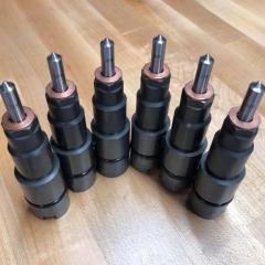


This leaderboard is set to Boise/GMT-06:00