


Mopar1973Man
Owner
-
Joined
-
Last visited
Everything posted by Mopar1973Man
-
P07BF - 00 - Input - Turbine Shaft Speed Sensor 1 Circuit Low For a complete TRANSMISSION wiring diagram, (refer to the Wiring Information) . Theory of Operation The purpose of the diagnostic is to check the turbine speed sensor circuit for electrical failures by continuously monitoring the sensor output circuit for voltage high, low, or open conditions. The turbine speed sensor is a Hall Effect sensor that has an output range that alternates between normal high and normal low voltages as the turbine tone wheel rotates. If the measured turbine speed sensor output circuit voltage is greater than or equal to a calibrated high threshold (circuit high) or is less than or equal to a calibrated low threshold (circuit low or open) for a calibrated amount of time, a DTC will set. When Monitored and Set Conditions When Monitored: This diagnostic runs continuously when the following conditions are met: • TCM supply voltage is between 10 and 16 volts. • Engine speed (CAN message) is greater than 550 rpm. Set Conditions: • Input speed sensor output circuit voltage is less than or equal to 0.225 volts for less than 1 second. Possible Causes INPUT SPEED SENSOR SUPPLY (+) CIRCUIT OPEN INPUT SPEED SENSOR SUPPLY (+) CIRCUIT SHORTED TO GROUND INPUT SPEED SENSOR SIGNAL (-) CIRCUIT OPEN INPUT SPEED SENSOR SIGNAL (-) CIRCUIT SHORTED TO GROUND INPUT SPEED SENSOR TRANSMISSION CONTROL MODULE (TCM) Always perform the PRE-DIAGNOSTIC TROUBLESHOOTING PROCEDURE before proceeding. (Refer to 28 - DTC-Based Diagnostics/MODULE, Transmission Control (TCM) /Standard Procedure). Diagnostic Test 1. CHECK FOR AN ACTIVE DTC 1. With the scan tool, read TCM DTCs and record on the repair order. 2. Record the Event Data and Environmental Data. 3. With the scan tool, erase DTCs. 4. Using the recorded Event and Environmental Data, along with the When Monitored and Set Conditions above, operate the vehicle in the conditions that set the DTC. 5. With the scan tool, read TCM DTCs. Did the DTC return? Yes • Go To 2 No • Go To 12 2. CHECK THE INPUT SPEED SENSOR SUPPLY 1. Connect the scan tool to the vehicle. 2. Start the engine. NOTE: It may be necessary to allow the vehicle to allow the vehicle to roll while in a driven gear to see the voltage switching. If necessary to perform this test with the vehicle not stationary, enlist the aid of another person to operate the vehicle while monitoring the scan tool. 3. Place the vehicle in gear. 4. Monitor the Input Speed Sensor Supply voltage with the scan tool. Does the voltage switch from high (more than 1.2V) to Low (less than .8V) continuously? Yes • Go To 3 No • Replace Input Speed Sensor Supply and Transmission internal wiring in accordance with the Service Information. (Refer to 21 - Transmission and Transfer Case/Automatic - AS69RC/SENSOR, Speed/Removal) . • Perform TRANSMISSION VERIFICATION TEST (Refer to 28 - DTC-Based Diagnostics/MODULE, Transmission Control (TCM) - Standard Procedure). 3. CHECK WIRING AND CONNECTIONS AT THE I-255 CONNECTOR 1. Turn the ignition off. 2. Disconnect and check the I-255 connector. 3. Inspect the harness connectors and all male and female terminals for the following conditions: Proper connector installation. Damaged connector locks. Corrosion. Other signs of water intrusion. Weather seal damage (if equipped). Bent terminals. Terminals that have been pushed back into the connector cavity. Perform a terminal drag test on each connector terminal to verify proper terminal tension. 4. Using the schematics as a guide, inspect the wiring and connectors specific to this circuit. 5. Wiggle the wires while checking for shorted or open circuits. Were any problems found? Yes • Repair as necessary. • Perform the TRANSMISSION VERIFICATION TEST. (Refer to 28 - DTC-Based Diagnostics/MODULE, Transmission Control (TCM) /Standard Procedure). No • Go To 4 4. CHECK THE (T69) INPUT SPEED SENSOR SUPPLY (+) CIRCUIT FOR AN OPEN 1. Disconnect the I-255 harness connector. 2. Disconnect the Transmission Harness Pass Through connector. 3. Measure the resistance of the (T69) Input Speed Sensor Supply (+) circuit between the Transmission harness connector and the I-255 (Transmission Side) harness connector. Is the resistance below 3.0 Ohms? Yes • Go To 5 No • Repair the (T69) Input Speed Sensor Supply (+) circuit for an open. • Perform the TRANSMISSION VERIFICATION TEST (Refer to 28 - DTC-Based Diagnostics/MODULE, Transmission Control (TCM) - Standard Procedure). 5. CHECK THE (T69) INPUT SPEED SENSOR SUPPLY (+) CIRCUIT FOR A SHORT TO GROUND 1. Disconnect the I-255 harness connector. 2. Disconnect the Transmission Harness Pass Through Connector. 3. Check for continuity between ground and the (T69) Input Speed Sensor Supply (+) circuit at the I-255 (Transmission Side) harness connector. Is there continuity between ground and the (T69) Input Speed Sensor Supply (+) circuit? Yes • Repair the (T69) Input Speed Sensor Supply (+) circuit for a short to ground. • Perform the TRANSMISSION VERIFICATION TEST (Refer to 28 - DTC-Based Diagnostics/MODULE, Transmission Control (TCM) - Standard Procedure). No • Go To 6 6. CHECK THE (T52) INPUT SPEED SENSOR SIGNAL (-) CIRCUIT FOR AN OPEN 1. Disconnect the I-255 harness connector. 2. Disconnect the transmission pass through harness connector. 3. Measure the resistance of the (T52) Input Speed Sensor Signal (-) circuit between the Transmission Assembly harness connector and the I-255 (Transmission Side) harness connector. Is the resistance below 3.0 Ohms? Yes • Go To 7 No • Repair the (T52) Input Speed Sensor Signal (-) circuit for an open. • Perform the TRANSMISSION VERIFICATION TEST (Refer to 28 - DTC-Based Diagnostics/MODULE, Transmission Control (TCM) - Standard Procedure). 7. CHECK THE (T52) INPUT SPEED SENSOR SIGNAL (-) CIRCUIT FOR A SHORT TO GROUND 1. Disconnect the I-255 harness connector. 2. Disconnect the transmission pass through harness connector. 3. Check for continuity between ground and the (T52) Input Speed Sensor Signal (-) circuit at the I-255 (Transmission Side) harness connector. Is there continuity between ground and the (T52) Input Speed Sensor Signal (-) circuit? Yes • Repair the (T52) Input Speed Sensor Signal (-) circuit for a short to ground. • Perform the TRANSMISSION VERIFICATION TEST (Refer to 28 - DTC-Based Diagnostics/MODULE, Transmission Control (TCM) - Standard Procedure). No • Go To 8 8. CHECK THE (T69) INPUT SPEED SENSOR SUPPLY (+) CIRCUIT FOR AN OPEN 1. Disconnect the TCM C-1 harness connector. 2. Disconnect the I-255 harness connector. 3. Measure the resistance of the (T69) Input Speed Sensor Supply (+) circuit between the TCM C-1 harness connector and the I-255 (TCM Side) harness connector. Is the resistance below 3.0 Ohms? Yes • Go To 9 No • Repair the (T69) Input Speed Sensor Supply (+) circuit for an open. • Perform the TRANSMISSION VERIFICATION TEST (Refer to 28 - DTC-Based Diagnostics/MODULE, Transmission Control (TCM) - Standard Procedure). 9. CHECK THE (T69) INPUT SPEED SENSOR SUPPLY (+) CIRCUIT FOR A SHORT TO GROUND 1. Disconnect the TCM C-1 harness connector. 2. Disconnect the I-255 harness connector. 3. Check for continuity between ground and the (T69) Input Speed Sensor Supply (+) circuit at the I-255 (TCM Side) harness connector. Is there continuity between ground and the (T69) Input Speed Sensor Supply (+) circuit? Yes • Repair the (T69) Input Speed Sensor Supply (+) circuit for a short to ground. • Perform the TRANSMISSION VERIFICATION TEST (Refer to 28 - DTC-Based Diagnostics/MODULE, Transmission Control (TCM) - Standard Procedure). No • Go To 10 10. CHECK THE (T52) INPUT SPEED SENSOR SIGNAL (-) CIRCUIT FOR AN OPEN 1. Disconnect the TCM C-1 harness connector. 2. Disconnect the I-255 harness connector. 3. Measure the resistance of the (T52) Input Speed Sensor Signal (-) circuit between the TCM C-1 harness connector and the I-255 (TCM Side) harness connector. Is the resistance below 3.0 Ohms? Yes • Go To 11 No • Repair the (T52) Input Speed Sensor Signal (-) circuit for an open. • Perform the TRANSMISSION VERIFICATION TEST (Refer to 28 - DTC-Based Diagnostics/MODULE, Transmission Control (TCM) - Standard Procedure). 11. CHECK THE (T52) INPUT SPEED SENSOR SIGNAL (-) CIRCUIT FOR A SHORT TO GROUND 1. Disconnect the TCM C-1 harness connector. 2. Disconnect the I-255 harness connector. 3. Check for continuity between ground and the (T52) Input Speed Sensor Signal (-) circuit at the I-255 (TCM Side) harness connector. Is there continuity between ground and the (T52) Input Speed Sensor Signal (-) circuit? Yes • Repair the (T52) Input Speed Sensor Signal (-) circuit for a short to ground. • Perform the TRANSMISSION VERIFICATION TEST (Refer to 28 - DTC-Based Diagnostics/MODULE, Transmission Control (TCM) - Standard Procedure). No • Replace the Input Speed Sensor in accordance with the Service Information. (Refer to 21 -Transmission and Transfer Case/Automatic - AS69RC/SENSOR, Speed/Removal) . • Perform the TRANSMISSION VERIFICATION TEST. (Refer to 28 - DTC-Based Diagnostics/MODULE, Transmission Control (TCM) /Standard Procedure). DTC Returned after TRANSMISSION VERIFICATION TEST. • If the DTC returns after replacing the Input Speed Sensor, replace the Transmission Control Module (TCM) in accordance with the Service information. (Refer to 08 - Electrical/8E - Electronic Control Modules/MODULE, Transmission Control/Removal) . • Perform the TRANSMISSION VERIFICATION TEST. (Refer to 28 - DTC-Based Diagnostics/MODULE, Transmission Control (TCM) /Standard Procedure). DTC did not return after TRANSMISSION VERIFICATION TEST. • Test complete. 12. CHECK WIRING AND I-255 CONNECTOR FOR INTERMITTENT CONNECTIONS NOTE: The conditions necessary to set the DTC are not present at this time. The code set because of an intermittent condition. Try to determine the cause in this step. Turn the ignition off. 1. Disconnect all TCM harness connectors. 2. Disconnect all related in-line harness connections (if equipped). 3. Disconnect the related component harness connectors. 4. Inspect harness connectors, component connectors, and all male and female terminals for the following conditions: Proper connector installation. Damaged connector locks. Corrosion. Other signs of water intrusion. Weather seal damage (if equipped). Bent terminals. Terminals that have been pushed back into the connector cavity. Perform a terminal drag test on each connector terminal to verify proper terminal tension. 5. Using the schematics as a guide, inspect the wiring and connectors specific to this circuit. 6. Wiggle the wires while checking for shorted and open circuits. Were any problems found? Yes • Repair as necessary. • Perform the TRANSMISSION VERIFICATION TEST. (Refer to 28 - DTC-Based Diagnostics/MODULE, Transmission Control (TCM) /Standard Procedure). No • Perform the TRANSMISSION VERIFICATION TEST. (Refer to 28 - DTC-Based Diagnostics/MODULE, Transmission Control (TCM) /Standard Procedure). • Test complete.
-
Consider it carefully on the rear axle gearing and the top gear of the transmission. As you found how it changed your truck getting the gearing correct. I've got that other member with Allison Transmission and the final gear is pretty tall and running way too low in top gear at 65 MPH.
-
P06D8 - Sensor Reference Voltage 6 Circuit High Theory of Operation This sensor supply circuit provides a 5-Volt supply to the Fuel Rail Pressure (FRP) Sensor. The Powertrain Control Module (PCM) illuminates the MIL lamp immediately after the diagnostic runs and fails. The ETC lamp will also flash. During this time the customer will be in a limp home mode. The PCM will turn off the MIL lamp after the diagnostic runs and passes in four consecutive drive cycles. When Monitored: While the engine is running. Set Condition: Voltage detected on the 5-Volt Supply circuit is above a calibrated value. Possible Causes 5-VOLT SUPPLY CIRCUIT SHORTED TO VOLTAGE POWERTRAIN CONTROL MODULE (PCM) Always perform the Pre-Diagnostic Troubleshooting procedure before proceeding. (Refer to 28 - DTC-Based Diagnostics/MODULE, Powertrain Control (PCM) - Standard Procedure). Diagnostic Test 1. ACTIVE DTC 1. Turn the ignition on. 2. With the scan tool, record all Freeze frame data. 3. With the scan tool, erase DTCs. 4. Turn the ignition off for 75 seconds. 5. Turn the ignition on. 6. With the scan tool, read DTCs. Did the DTC reset? Yes • Go To 2 No • Perform the INTERMITTENT CONDITION diagnostic procedure. (Refer to 28 - DTC-Based Diagnostics/MODULE, Powertrain Control (PCM) - Standard Procedure). 2. CHECK THE (K350) 5-VOLT SUPPLY CIRCUIT FOR A SHORT TO VOLTAGE 1. Turn the ignition off. 2. Disconnect the FRP sensor harness connector. 3. Turn the ignition on. 4. Measure the voltage of the (K350) 5-Volt Supply circuit at FRP sensor harness connector. Is the voltage reading above 5.1 Volts? Yes • Repair the (K350) 5-Volt Supply circuit for a short to voltage. • Perform the POWERTRAIN VERIFICATION TEST - 6.7L. (Refer to 28 - DTC-Based Diagnostics/MODULE, Powertrain Control (PCM) - Standard Procedure). No • Go To 3 3. CHECK THE (K350) 5-VOLT SUPPLY CIRCUIT FOR A SHORT TO ANOTHER CIRCUIT 1. Turn the ignition off. 2. Disconnect the PCM C1 harness connector. NOTE: Check connectors - Clean/repair as necessary. 3. Measure the resistance between the (K350) 5-Volt Supply circuit and all other circuits in the PCM C1 connector. Is the resistance below 10k Ohms? Yes • Repair the short from the (K350) 5-Volt Supply circuit to the circuit that measured below 10k Ohms. • Perform the POWERTRAIN VERIFICATION TEST - 6.7L. (Refer to 28 - DTC-Based Diagnostics/MODULE, Powertrain Control (PCM) - Standard Procedure). No • Replace the Powertrain Control Module in accordance with the service information. • Perform the POWERTRAIN VERIFICATION TEST - 6.7L. (Refer to 28 - DTC-Based Diagnostics/MODULE, Powertrain Control (PCM) - Standard Procedure).
-
P06D7 - Sensor Reference Voltage 6 Circuit Low Theory of Operation This sensor supply circuit provides a 5-Volt supply to the Fuel Rail Pressure (FRP) Sensor. The Powertrain Control Module (PCM) illuminates the MIL lamp immediately after the diagnostic runs and fails. The ETC lamp will also flash. During this time the customer will be in a limp home mode. The PCM will turn off the MIL lamp after the diagnostic runs and passes in four consecutive drive cycles. When Monitored: With the ignition on, PCM powered. Set Condition: Low voltage detected at the 5-Volt Supply circuit. Possible Causes FUEL RAIL PRESSURE (FRP) SENSOR 5-VOLT SUPPLY CIRCUIT SHORTED TO GROUND POWERTRAIN CONTROL MODULE (PCM) Always perform the Pre-Diagnostic Troubleshooting procedure before proceeding. (Refer to 28 - DTC-Based Diagnostics/MODULE, Powertrain Control (PCM) - Standard Procedure). Diagnostic Test 1. ACTIVE DTC 1. Turn the ignition on. 2. Using the scan tool, record all Freeze frame data. 3. Using the scan tool, erase DTCs. 4. Turn the ignition off for 75 seconds. 5. Turn the ignition on. 6. Using the scan tool, read DTCs. Did the DTC reset? Yes • Go To 2 No • Perform the INTERMITTENT CONDITION diagnostic procedure. (Refer to 28 - DTC-Based Diagnostics/MODULE, Powertrain Control (PCM) - Standard Procedure). 2. CHECK THE FRP SENSOR 1. Turn the ignition off. 2. Disconnect the FRP sensor harness connector. 3. Turn the ignition on. 4. Measure the voltage on the (K350) 5-Volt Supply circuit at the FRP sensor harness connector. Is the voltage reading between 4.9 and 5.1 Volts? Yes • Replace the Fuel Rail Pressure Sensor in accordance with the service information. • Perform the POWERTRAIN VERIFICATION TEST - 6.7L. (Refer to 28 - DTC-Based Diagnostics/MODULE, Powertrain Control (PCM) - Standard Procedure). No • Go To 3 3. CHECK THE (K350) 5-VOLT SUPPLY CIRCUIT FOR A SHORT TO GROUND 1. Disconnect the PCM C1 harness connector. 2. Measure the resistance between ground and the (K350) 5-Volt Supply circuit at the PCM C1 harness connector. Is the resistance below 10k Ohms? Yes • Repair the (K350) 5-Volt Supply circuit for a short to ground. • Perform the POWERTRAIN VERIFICATION TEST - 6.7L. (Refer to 28 - DTC-Based Diagnostics/MODULE, Powertrain Control (PCM) - Standard Procedure). No • Replace the Powertrain Control Module in accordance with the service information. • Perform the POWERTRAIN VERIFICATION TEST - 6.7L. (Refer to 28 - DTC-Based Diagnostics/MODULE, Powertrain Control (PCM) - Standard Procedure).
-
P06D4 - Sensor Reference Voltage 5 Circuit High Theory of Operation This sensor supply circuit provides a 5-Volt supply to the Accelerator Pedal Position 2 Sensor (APPS), Diesel Particulate Filter Pressure Sensor, Soot Delta Pressure Sensor, and the Transmission Pressure Sensor. The Powertrain Control Module (PCM) illuminates the MIL lamp immediately after the diagnostic runs and fails. The ETC lamp will also flash. During this time the customer will be in a limp home mode. The PCM will turn off the MIL lamp after the diagnostic runs and passes in four consecutive drive cycles. When Monitored: While the engine is running. Set Condition: Voltage detected on the 5-Volt Supply circuit is above a calibrated value. Possible Causes 5-VOLT SUPPLY CIRCUIT SHORTED TO VOLTAGE POWERTRAIN CONTROL MODULE (PCM) Always perform the Pre-Diagnostic Troubleshooting procedure before proceeding. (Refer to 28 - DTC- Based Diagnostics/MODULE, Powertrain Control (PCM) - Standard Procedure). Diagnostic Test 1. ACTIVE DTC 1. Turn the ignition on. 2. With the scan tool, record all Freeze frame data. 3. With the scan tool, erase DTCs. 4. Turn the ignition off for 75 seconds. 5. Turn the ignition on. 6. With the scan tool, read DTCs. Did the DTC reset? Yes • Go To 2 No • Perform the INTERMITTENT CONDITION diagnostic procedure. (Refer to 28 - DTC-Based Diagnostics/MODULE, Powertrain Control (PCM) - Standard Procedure). 2. CHECK THE (F856) 5-VOLT SUPPLY FOR A SHORT TO VOLTAGE 1. Turn the ignition off. 2. Disconnect the components listed in the theory of operation. 3. Turn the ignition on. 4. Measure the voltage of the (F856) 5-Volt Supply circuit at the Accelerator Pedal Position harness connector. Is the voltage reading above 5.1 Volts? Yes • Repair the (F856) 5-Volt Supply circuit for a short to voltage. • Perform the POWERTRAIN VERIFICATION TEST - 6.7L. (Refer to 28 - DTC-Based Diagnostics/MODULE, Powertrain Control (PCM) - Standard Procedure). No • Go To 3 3. CHECK THE (F856) 5-VOLT SUPPLY CIRCUIT FOR A SHORT TO ANOTHER CIRCUIT 1. Turn the ignition off. 2. Disconnect the PCM C2 harness connector. NOTE: Check connectors - Clean/repair as necessary. 3. Measure the resistance between the (F856) 5-Volt Supply circuit and all other circuits in the PCM C2 connector. Is the resistance below 10k Ohms between the (F856) 5-Volt Supply circuit and any of the circuits? Yes • Repair the short between the (F856) 5-Volt Supply circuit and the circuit that measured below 10k Ohms. • Perform the POWERTRAIN VERIFICATION TEST - 6.7L. (Refer to 28 - DTC-Based Diagnostics/MODULE, Powertrain Control (PCM) - Standard Procedure). No • Replace the Powertrain Control Module in accordance with the service information. • Perform the POWERTRAIN VERIFICATION TEST - 6.7L. (Refer to 28 - DTC-Based Diagnostics/MODULE, Powertrain Control (PCM) - Standard Procedure).
-
P06D3 - Sensor Reference Voltage 5 Circuit Low Theory of Operation This sensor supply circuit provides a 5-Volt supply to the Accelerator Pedal Position 2 Sensor (APPS), Diesel Particulate Filter Pressure Sensor, Soot Delta Pressure Sensor, and the Transmission Pressure Sensor. The Powertrain Control Module (PCM) illuminates the MIL lamp immediately after the diagnostic runs and fails. The ETC lamp will also flash. During this time the customer will be in a limp home mode. The PCM will turn off the MIL lamp after the diagnostic runs and passes in four consecutive drive cycles. When Monitored: With the ignition on, PCM powered. Set Condition: Low voltage detected at the 5-Volt Supply circuit. Possible Causes APP 2 SENSOR DIESEL PARTICULATE FILTER PRESSURE SENSOR SOOT DELTA PRESSURE SENSOR TRANSMISSION LINE PRESSURE SENSOR (66RFE ONLY) 5-VOLT SUPPLY CIRCUIT SHORTED TO GROUND POWERTRAIN CONTROL MODULE (PCM) Always perform the Pre-Diagnostic Troubleshooting procedure before proceeding. (Refer to 28 - DTC-Based Diagnostics/MODULE, Powertrain Control (PCM) - Standard Procedure). Diagnostic Test 1. ACTIVE DTC 1. Turn the ignition on. 2. With the scan tool, record all Freeze frame data. 3. With the scan tool, erase DTCs. 4. Turn the ignition off for 75 seconds. 5. Turn the ignition on. 6. With the scan tool, read DTCs. Did the DTC reset? Yes • Go To 2 No • Perform the INTERMITTENT CONDITION diagnostic procedure. (Refer to 28 - DTC-Based Diagnostics/MODULE, Powertrain Control (PCM) - Standard Procedure). 2. CHECK THE APPS SENSOR 2 1. Ignition on. 2. Disconnect the Accelerator Pedal Position Sensor harness connector. NOTE: Check connectors - Clean/repair as necessary. 3. Measure the voltage on the (F856) 5-Volt Supply circuit at the Accelerator Pedal Position Sensor harness connector. Is the voltage reading between 4.9 and 5.1 Volts? Yes • Replace the Accelerator Pedal Position Sensor in accordance with the service information. • Perform the POWERTRAIN VERIFICATION TEST - 6.7L. (Refer to 28 - DTC-Based Diagnostics/MODULE, Powertrain Control (PCM) - Standard Procedure). No • Go To 3 3. CHECK THE DIESEL PARTICULATE FILTER PRESSURE SENSOR 1. Disconnect the Diesel Particulate Filter Pressure Sensor harness connector. NOTE: Check connectors - Clean/repair as necessary. 2. Measure the voltage on the (F856) 5-Volt Supply circuit at the Diesel Particulate Filter Pressure Sensor harness connector. Is the voltage reading between 4.9 and 5.1 Volts? Yes • Replace the Diesel Particulate Filter Pressure Sensor in accordance with the service information. • Perform the POWERTRAIN VERIFICATION TEST - 6.7L. (Refer to 28 - DTC-Based Diagnostics/MODULE, Powertrain Control (PCM) - Standard Procedure). No • Go To 4 4. CHECK THE SOOT DELTA PRESSURE SENSOR 1. Disconnect the Soot Delta Pressure Sensor harness connector. NOTE: Check connectors - Clean/repair as necessary. 2. Measure the voltage on the (F856) 5-Volt Supply circuit at the Soot Delta Pressure Sensor harness connector. Is the voltage reading between 4.9 and 5.1 Volts? Yes • Replace the Soot Delta Pressure Sensor in accordance with the service information. • Perform the POWERTRAIN VERIFICATION TEST - 6.7L. (Refer to 28 - DTC-Based Diagnostics/MODULE, Powertrain Control (PCM) - Standard Procedure). No • Go To 5 5. CHECK THE TRANSMISSION LINE PRESSURE SENSOR (66RFE ONLY) 1. Disconnect the Transmission Pressure Sensor harness connector. NOTE: Check connectors - Clean/repair as necessary. 2. Measure the voltage on the (F856) 5-Volt Supply circuit at the Transmission Pressure Sensor harness connector. Is the voltage reading between 4.9 and 5.1 Volts? Yes • Replace the Transmission Line Pressure Sensor in accordance with the service information. • Perform the POWERTRAIN VERIFICATION TEST - 6.7L. (Refer to 28 - DTC-Based Diagnostics/MODULE, Powertrain Control (PCM) - Standard Procedure). No • Go To 6 6. CHECK THE (F856) 5-VOLT SUPPLY CIRCUIT FOR A SHORT TO GROUND 1. Turn the ignition off. 2. Disconnect the PCM C2 harness connector. 3. Check connectors - Clean/repair as necessary. 4. Measure the resistance between ground and the (F856) 5-Volt Supply circuit at the Diesel Particulate Filter Pressure Sensor harness connector. Is the resistance below 10k Ohms? Yes • Repair the (F856) 5-Volt Supply circuit for a short to ground. • Perform the POWERTRAIN VERIFICATION TEST - 6.7L. (Refer to 28 - DTC-Based Diagnostics/MODULE, Powertrain Control (PCM) - Standard Procedure). No • Replace and program the Powertrain Control Module in accordance with the service information. • Perform the POWERTRAIN VERIFICATION TEST - 6.7L. (Refer to 28 - DTC-Based Diagnostics/MODULE, Powertrain Control (PCM) - Standard Procedure).
-
P06A5 - Sensor Reference Voltage 4 Circuit High Theory of Operation This sensor supply circuit provides a 5-Volt supply to the Accelerator Pedal Position 1 Sensor (APPS) and the A/C Pressure Sensor. The Powertrain Control Module (PCM) illuminates the MIL lamp immediately after the diagnostic runs and fails. The ETC lamp will also flash. During this time the customer will be in a limp home mode. The PCM will turn off the MIL lamp after the diagnostic runs and passes in four consecutive drive cycles. When Monitored: With the ignition on, PCM powered. Set Condition: Voltage detected at the 5-Volt Supply circuit is above a calibrated value. Possible Causes 5-VOLT SUPPLY SHORT TO VOLTAGE POWERTRAIN CONTROL MODULE (PCM) Always perform the Pre-Diagnostic Troubleshooting procedure before proceeding. (Refer to 28 - DTC-Based Diagnostics/MODULE, Powertrain Control (PCM) - Standard Procedure). 1. ACTIVE DTC 1. Turn the ignition on. 2. With the scan tool, record all Freeze frame data. 3. With the scan tool, erase DTCs. 4. Turn the ignition off for 75 seconds. 5. Turn the ignition on. 6. With the scan tool, read DTCs. Did the DTC reset? Yes • Go To 2 No Perform the INTERMITTENT CONDITION diagnostic procedure. (Refer to 28 - DTC-Based Diagnostics/MODULE, Powertrain Control (PCM) - Standard Procedure). 2. CHECK THE (F855) 5-VOLT SUPPLY CIRCUIT FOR A SHORT TO VOLTAGE 1. Turn the ignition off. 2. Disconnect the Accelerator Pedal Position harness connector. 3. Turn the ignition on. 4. Measure the voltage of the (F855) 5-Volt Supply circuit at the Accelerator Pedal Position harness connector. Is the voltage reading above 5.1 Volts? Yes • Repair the (F855) 5-Volt Supply circuit for a short to voltage. • Perform the POWERTRAIN VERIFICATION TEST - 6.7L. (Refer to 28 - DTC-Based Diagnostics/MODULE, Powertrain Control (PCM) - Standard Procedure). No • Go To 3 3. CHECK THE (F855) 5-VOLT SUPPLY CIRCUIT FOR A SHORT TO ANOTHER CIRCUIT 1. Turn the ignition off. 2. Disconnect the PCM C2 harness connector. NOTE: Check connectors - Clean/repair as necessary. 3. Measure the resistance between the (F855) 5-Volt Supply circuit and all other circuits in the PCM C2 connector. Is the resistance below 10k Ohms between the (F855) 5-Volt Supply circuit and any of the circuits? Yes • Repair the short to the circuit that measured below 10k Ohms. • Perform the POWERTRAIN VERIFICATION TEST - 6.7L. (Refer to 28 - DTC-Based Diagnostics/MODULE, Powertrain Control (PCM) - Standard Procedure). No • Replace the Powertrain Control Module in accordance with the service information. • Perform the POWERTRAIN VERIFICATION TEST - 6.7L. (Refer to 28 - DTC-Based Diagnostics/MODULE, Powertrain Control (PCM) - Standard Procedure).
-
P06A4 - Sensor Reference Voltage 4 Circuit Low Theory of Operation This sensor supply circuit provides a 5-Volt supply to the Accelerator Pedal Position 1 Sensor (APPS) and the A/C Pressure Sensor. The Powertrain Control Module (PCM) illuminates the MIL lamp immediately after the diagnostic runs and fails. The ETC lamp will also flash. During this time the customer will be in a limp home mode. The PCM will turn off the MIL lamp after the diagnostic runs and passes in four consecutive drive cycles. When Monitored: With the key on. Set Condition: Voltage detected on the 5-Volt supply circuit is below a calibrated value. Possible Causes 5-VOLT SUPPLY CIRCUIT SHORTED TO GROUND APP 1 SENSOR A/C PRESSURE SENSOR POWERTRAIN CONTROL MODULE (PCM) Always perform the Pre-Diagnostic Troubleshooting procedure before proceeding. (Refer to 28 - DTC-Based Diagnostics/MODULE, Powertrain Control (PCM) - Standard Procedure). 1. ACTIVE DTC 1. Turn the ignition on. 2. With the scan tool, record all Freeze frame data. 3. With the scan tool, erase DTCs. 4. Turn the ignition off for 75 seconds. 5. Turn the ignition on. 6. With the scan tool, read DTCs. Did the DTC reset? Yes • Go To 2 No • Perform the INTERMITTENT CONDITION diagnostic procedure. (Refer to 28 - DTC-Based Diagnostics/MODULE, Powertrain Control (PCM) - Standard Procedure). 2. CHECK THE APP SENSOR 1 1. Ignition on. 2. Disconnect the Accelerator Pedal Position Sensor harness connector. NOTE: Check connectors - Clean/repair as necessary. 3. Measure the voltage on the (F855) 5-Volt Supply circuit at the Accelerator Pedal Position Sensor harness connector. Is the voltage reading between 4.9 and 5.1 Volts? Yes • Replace the Accelerator Pedal Position Sensor in accordance with the service information. • Perform the POWERTRAIN VERIFICATION TEST - 6.7L. (Refer to 28 - DTC-Based Diagnostics/MODULE, Powertrain Control (PCM) - Standard Procedure). No • Go To 3 3. CHECK THE A/C PRESSURE SENSOR 1. Disconnect the A/C Pressure Sensor harness connector. NOTE: Check connectors - Clean/repair as necessary. 2. Measure the voltage on the (F855) 5-Volt Supply circuit at the A/C Pressure Sensor harness connector. Is the voltage reading between 4.9 and 5.1 Volts? Yes • Replace the A/C Pressure Sensor in accordance with the service information. • Perform the POWERTRAIN VERIFICATION TEST - 6.7L. (Refer to 28 - DTC-Based Diagnostics/MODULE, Powertrain Control (PCM) - Standard Procedure). No • Go To 4 4. CHECK THE (F855) 5-VOLT SUPPLY CIRCUIT FOR A SHORT TO GROUND 1. Turn the ignition off. 2. Disconnect the PCM C2 harness connector. 3. Check connectors - Clean/repair as necessary. 4. Measure the resistance between ground and the (F855) 5-Volt Supply circuit at the Accelerator Pedal Position Sensor harness connector. Is the resistance below 10k Ohms? Yes • Repair the (F855) 5-Volt Supply circuit for a short to ground. • Perform the POWERTRAIN VERIFICATION TEST - 6.7L. (Refer to 28 - DTC-Based Diagnostics/MODULE, Powertrain Control (PCM) - Standard Procedure). No • Go To 5 5. CHECK THE (F855) 5-VOLT SUPPLY CIRCUIT FOR A SHORT TO ANOTHER CIRCUIT 1. Measure the resistance between the (F855) 5-Volt Supply circuit and all other circuits at the PCM C2 harness connector. Is the resistance below 10k Ohms between the (F855) 5-Volt supply circuit and any of the circuits? Yes • Repair the short to the circuit that measured below 10k Ohms. • Perform the POWERTRAIN VERIFICATION TEST - 6.7L. (Refer to 28 - DTC-Based Diagnostics/MODULE, Powertrain Control (PCM) - Standard Procedure). No • Replace and program the Powertrain Control Module in accordance with the Service Information. • Perform the POWERTRAIN VERIFICATION TEST - 6.7L. (Refer to 28 - DTC-Based Diagnostics/MODULE, Powertrain Control (PCM) - Standard Procedure).
-
P04E4 - Crankcase Ventilation Hose Connection Sensor Circuit Intermittent/Erratic When Monitored: Ignition on and battery voltage above 10.4 Volts. Set Condition: At key on, engine not running the Crankcase Hose Pressure Sensor Signal being sent to the Powertrain Control Module is higher or lower than a calibrated threshold. Or, during engine operation, the Crankcase Pressure Hose Sensor Signal is not changing with engine operating conditions. Possible Causes CRANKCASE HOSE PRESSURE SENSOR POWERTRAIN CONTROL MODULE (PCM) Always perform the Pre-Diagnostic Troubleshooting procedure before proceeding. (Refer to 28 - DTC-Based Diagnostics/MODULE, Powertrain Control (PCM) - Standard Procedure). Diagnostic Test 1. DTC ACTIVE 1. Turn the ignition on. 2. With the scan tool, record all Freeze frame data. 3. With the scan tool, erase DTCs. 4. Turn the ignition off for 75 seconds. 5. Start the engine and let idle for one minute. 6. With the scan tool, read DTCs. Did DTC P04E4 return? Yes • Go To 2 No • Perform the INTERMITTENT CONDITION diagnostic procedure. (Refer to 28 - DTC-Based Diagnostics/MODULE, Powertrain Control (PCM) - Standard Procedure). 2. OTHER DTCS 1. With the scan tool, continue to read DTCs.. Does the scan tool display DTC P04E2 or DTC P04E3 active? Yes • Perform the diagnostics and repairs for those active DTCs before proceeding with this diagnostic tree. No • Go To 3 3. CRANKCASE HOSE PRESSURE SENSOR 1. Turn the ignition off for 75 seconds. 2. Turn the ignition on, engine not running. 3. Disconnect the Crankcase Hose Pressure Sensor. 4. With the scan tool, read DTCs. Does the scan tool display DTC P04E2 active? Yes • Replace the Crankcase Hose Pressure Sensor in accordance with the service information. • Perform the POWERTRAIN VERIFICATION TEST - 6.7L. (Refer to 28 - DTC-Based Diagnostics/MODULE, Powertrain Control (PCM) - Standard Procedure). No • Replace the Powertrain Control Module in accordance with the service information. • Perform the POWERTRAIN VERIFICATION TEST - 6.7L. (Refer to 28 - DTC-Based Diagnostics/MODULE, Powertrain Control (PCM) - Standard Procedure).
-
P04E3 - Crankcase Ventilation Hose Connection Sensor Circuit High When Monitored: Ignition on and battery voltage above 10.4 Volts. Set Condition: The Crankcase Hose Pressure Signal being sent to the Powertrain Control Module is above a calibrated threshhold. The Powertrain Control Module (PCM) will illuminate the Malfunction Indicator Lamp (MIL) after the diagnostic runs and fails in two consecutive drive cycles. Possible Causes CRANKCASE HOSE PRESSURE SIGNAL CIRCUIT SHORT TO VOLTAGE CRANKCASE HOSE PRESSURE SIGNAL CIRCUIT OPEN/HIGH RESISTANCE CRANKCASE HOSE PRESSURE RETURN CIRCUIT OPEN/HIGH RESISTANCE CRANKCASE HOSE PRESSURE SENSOR POWERTRAIN CONTROL MODULE (PCM) Always perform the Pre-Diagnostic Troubleshooting procedure before proceeding. (Refer to 28 - DTC-Based Diagnostics/MODULE, Powertrain Control (PCM) - Standard Procedure). Diagnostic Test 1. DTC ACTIVE 1. Turn the ignition on. 2. With the scan tool, record all Freeze frame data. 3. With the scan tool, erase DTCs. 4. Turn the ignition off for 75 seconds. 5. Start the engine and let idle for one minute. 6. With the scan tool, read DTCs. Did the DTC return? Yes • Go To 2 No • Perform the INTERMITTENT CONDITION diagnostic procedure. (Refer to 28 - DTC-Based Diagnostics/MODULE, Powertrain Control (PCM) - Standard Procedure). 2. CHECK THE (K664) CRANKCASE HOSE PRESSURE SIGNAL CIRCUIT FOR A SHORT TO VOLTAGE 1. Turn the ignition off. 2. Disconnect the Crankcase Hose Pressure Sensor harness connector. 3. Measure the voltage on the (K664) Crankcase Hose Pressure Signal circuit at the Crankcase Hose Pressure Sensor harness connector. Is the voltage above 5.1 Volts? Yes • Repair the (K664) Crankcase Hose Pressure Signal circuit for a short to voltage. • Perform the POWERTRAIN VERIFICATION TEST - 6.7L. (Refer to 28 - DTC-Based Diagnostics/MODULE, Powertrain Control (PCM) - Standard Procedure). No • Go To 3 3. CHECK THE (K664) CRANKCASE HOSE PRESSURE SIGNAL CIRCUIT FOR AN OPEN/HIGH RESISTANCE 1. Disconnect the PCM C1 harness connector. 2. Measure the resistance of the (K664) Crankcase Hose Pressure Signal circuit between the Crankcase Hose Pressure Sensor harness connector and the PCM C1 harness connector. Is the resistance below 10k Ohms? Yes • Repair the (K664) Crankcase Hose Pressure Signal circuit for an open/high resistance. • Perform the POWERTRAIN VERIFICATION TEST - 6.7L. (Refer to 28 - DTC-Based Diagnostics/MODULE, Powertrain Control (PCM) - Standard Procedure). No • Go To 4 4. CHECK THE (K916) CRANKCASE HOSE PRESSURE RETURN CIRCUIT FOR AN OPEN/HIGH RESISTANCE 1. Measure the resistance of the (K916) Crankcase Hose Pressure Return circuit between the Crankcase Hose Pressure Sensor harness connector and the PCM C1 harness connector. Is the resistance below 10k Ohms? Yes • Repair the (K916) Crankcase Hose Pressure Return circuit for an open/high resistance. • Perform the POWERTRAIN VERIFICATION TEST - 6.7L. (Refer to 28 - DTC-Based Diagnostics/MODULE, Powertrain Control (PCM) - Standard Procedure). No • Go To 5 5. CRANKCASE HOSE PRESSURE SENSOR 1. Reconnect the PCM C1 harness connector. 2. Turn the ignition on. 3. With the Crankcase Hose Pressure Sensor still disconnected, check the scan tool for DTCs. Does the scan tool display DTC P04E2 active? Yes • Replace the Crankcase Hose Pressure Sensor in accordance with the service information. • Perform the POWERTRAIN VERIFICATION TEST - 6.7L. (Refer to 28 - DTC-Based Diagnostics/MODULE, Powertrain Control (PCM) - Standard Procedure). No • Replace the Powertrain Control Module in accordance with the service information. • Perform the POWERTRAIN VERIFICATION TEST - 6.7L. (Refer to 28 - DTC-Based Diagnostics/MODULE, Powertrain Control (PCM) - Standard Procedure).
-
P04E2 - Crankcase Ventilation Hose Connection Sensor Circuit Low When Monitored: Ignition on and battery voltage above 10.4 Volts. Set Condition: The Crankcase Hose Pressure Signal sent to the Powertrain Control Module is below a calibrated threshhold. The Powertrain Control Module (PCM) will illuminate the Malfunction Indicator Lamp (MIL) after the diagnostic runs and fails in two consecutive drive cycles. Possible Causes CRANKCASE HOSE PRESSURE SIGNAL CIRCUIT SHORT TO GROUND CRANKCASE HOSE PRESSURE SIGNAL CIRCUIT OPEN/HIGH RESISTANCE CRANKCASE HOSE PRESSURE SENSOR POWERTRAIN CONTROL MODULE (PCM) Always perform the Pre-Diagnostic Troubleshooting procedure before proceeding. (Refer to 28 - DTC-Based Diagnostics/MODULE, Powertrain Control (PCM) - Standard Procedure). Diagnostic Test 1. DTC ACTIVE 1. Turn the ignition on. 2. With the scan tool, record all Freeze frame data. 3. With the scan tool, erase DTCs. 4. Turn the ignition off for 75 seconds. 5. Start the engine and let idle for one minute. 6. With the scan tool, read DTCs. Did the DTC return? Yes • Go To 2 No • Perform the INTERMITTENT CONDITION diagnostic procedure. (Refer to 28 - DTC-Based Diagnostics/MODULE, Powertrain Control (PCM) - Standard Procedure). 2. CHECK THE (K664) CRANKCASE HOSE PRESSURE SIGNAL CIRCUIT FOR A SHORT TO GROUND 1. Turn the ignition off. 2. Disconnect the Crankcase Hose Pressure Sensor harness connector. 3. Disconnect the PCM C1 harness connector. 4. Measure the resistance between ground and the (K664) Crankcase Hose Pressure Signal circuit at the Crankcase Hose Pressure Sensor harness connector. Is the resistance below 10k Ohms? Yes • Repair the (K664) Crankcase Hose Pressure Signal circuit for a short to ground. • Perform the POWERTRAIN VERIFICATION TEST - 6.7L. (Refer to 28 - DTC-Based Diagnostics/MODULE, Powertrain Control (PCM) - Standard Procedure). No • Go To 3 3. CHECK THE (K664) CRANKCASE HOSE PRESSURE SIGNAL CIRCUIT FOR AN OPEN/HIGH RESISTANCE 1. Measure the resistance of the (K664) Crankcase Hose Pressure Signal circuit between the Crankcase Hose Pressure Sensor harness connector and the PCM C1 harness connector. Is the resistance below 10k Ohms? Yes • Repair the (K664) Crankcase Hose Pressure Signal circuit for an open/high resistance. • Perform the POWERTRAIN VERIFICATION TEST - 6.7L. (Refer to 28 - DTC-Based Diagnostics/MODULE, Powertrain Control (PCM) - Standard Procedure). No • Go To 4 4. CHECK THE CRANKCASE HOSE PRESSURE SENSOR 1. Reconnect the PCM C1 harness connector. 2. Turn the ignition on. 3. While monitoring the scan tool, use a jumper to connect the (F857) 5-Volt Supply circuit to the (K664) Crankcase Hose Pressure Signal circuit at the Crankcase Hose Pressure Sensor harness connector. Does the scan tool display DTC P04E3 active? Yes • Replace the Crankcase Hose Pressure Sensor in accordance with the service information. • Perform the POWERTRAIN VERIFICATION TEST - 6.7L. (Refer to 28 - DTC-Based Diagnostics/MODULE, Powertrain Control (PCM) - Standard Procedure). No • Replace the Powertrain Control Module in accordance with the service information. • Perform the POWERTRAIN VERIFICATION TEST - 6.7L. (Refer to 28 - DTC-Based Diagnostics/MODULE, Powertrain Control (PCM) - Standard Procedure).
-
P04DB - Crankcase Ventilation System Disconnected When Monitored: Engine at operating temperature, driving at a steady speed. This monitor takes 10 minutes to completely run. Set Condition: Crankcase Pressure readings have been significantly elevated, as compared to historic trends saved in the Powertrain Control Module. Possible Causes DISCONNECTED CRANKCASE VENTILATION HOSE INTAKE SYSTEM LEAK CRANKCASE BREATHER FILTER CLOGGED Always perform the Pre-Diagnostic Troubleshooting procedure before proceeding. (Refer to 28 - DTC-Based Diagnostics/MODULE, Powertrain Control (PCM) - Standard Procedure). 1. CHECK THE CRANKCASE VENTILATION HOSE NOTE: If there are any DTCs present for the EGR Valve, EGR Airflow Control Valve, or any of the pressure sensors, perform the diagnostics for those DTCs before proceeding with this test procedure. 1. Visually inspect the Crankcase Ventilation Hose. Is the hose disconnected, cracked, pinched or damaged? Yes • Repair or replace the Crankcase Ventilation Hose in accordance with the service information. • Perform the POWERTRAIN VERIFICATION TEST - 6.7L. (Refer to 28 - DTC-Based Diagnostics/MODULE, Powertrain Control (PCM) - Standard Procedure). No • Go To 2 2. CHECK THE INTAKE SYSTEM FOR LEAKS 1. Perform the INTAKE AIR SYSTEM PRESSURE TEST diagnostic procedure. (Refer to 29 - Non-DTC Diagnostics/Drivability - Diesel - Diagnosis and Testing) . Were any Intake System leaks found? Yes • Perform the appropriate repair. • Perform the POWERTRAIN VERIFICATION TEST - 6.7L. (Refer to 28 - DTC-Based Diagnostics/MODULE, Powertrain Control (PCM) - Standard Procedure). No • Replace the Crankcase Breather Filter in accordance with the service information. • Perform the POWERTRAIN VERIFICATION TEST - 6.7L. (Refer to 28 - DTC-Based Diagnostics/MODULE, Powertrain Control (PCM) - Standard Procedure).
-
I would love to see that truck when its done. I'm going to be heading east to Pigeon Forge TN. To bad I can't cross paths with you and see it sooner. I gather I'll just have to be patient.
-
I know my camera work needs some improvement but I'm learning as quickly as a can to keep pumping videos and articles out. Hopefully this will help other install a draw straw the right way and stopping the 1/4 tank slosh issues. I've got to finish up the install of the AirDog. There will be another article on the custom install of the pump and bracket for this truck it will not be a standard install at all being the truck is not a stock fit and finish truck so this will be another article and video coming very soon.
-
Just had that same conversation with him on the phone. Great minds think a like. @Tractorman
-
If it was me I would keep your truck and store it away till you can deal with things easier.
-
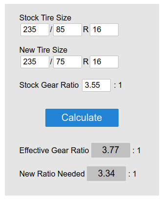
Non standard tire that will most likely be difficult to get. Here is the math on the 235/75 R16 tires.
-
AirDog Draw Straw installation You will need a 15mm socket and 1/2 ratchet for the bands on the tank. You'll also need a flat blade screwdriver, hammer, floor jack, and a ratchet strap. The way I remove the fuel tank is to place the jack under the tank just to support the weight. Then wrap a ratchet strap around the fuel tank and hook it to the jack pivot pin. Tighten the strap lightly not enough to crush the tank. You need to take a screwdriver and hammer and lightly tap on the sender ring and loosen the ring up to allow the sender to stand up out of the fuel tank. No need to unhook any lines leave that alone for now. Now using a 15mm socket you can remove the two nuts holding the fuel tank bands up to the frame. Pull your bands down and might have to bend them a bit to get out. Then easy the fuel tank down to the floor slowly and carefully to the floor watching the sender not to damage the fuel, sender in the tank, Once the tank is on the floor the sender can be lifted out of the fuel tank and the fuel tank moved out of your way. NOTE: You'll want to have a friend or buddy help you tip the tank over and dump the fuel out of the tank. The tank needs to be empty as much as possible to get the measurement correct. The current AirDog Draw Straw is different than the older generation I have in my truck. Make sure to support the tank at the normal band locations with 2x4 boards. WARNING: Do not leave the tank laying on the floor for measuring or any work it will deflect the tank bottom inward and skew your measurements also will create the 1/4 tank slosh issues! This now requires a 1-inch hole drilled into the top of the tank. You will need to inspect the location of where you're going to install that draw straw and be sure there is nothing going to interfere with the lines or the bulkhead sticking up. Make sure to clean the area where you are going to drill the 1-inch hole. Now drill the hole and collect all the drilled crumbs without getting into the tank if possible, Grab two quarters and lay them in the bottom, and stack the straw on top of the quarters. Now using a Sharpie mark the straw at the top of the tank. Now you want to measure from the bulkhead down to your mark and take note of that measurement, Now measure from the tip back up to the same measurement and mark the cut line. NOTE: If you are using 1 quarter you want to follow the AirDog method of holes drilled in the straw. If you use 2 quarters then no notches should be required. WARNING: Cut the straw "straight". Do NOT cut the straw at an angle or anything else but straight. When the straw is cut now place the sealing washer on the bulkhead and install the draw straw. The flat washer, star washer, and nut go inside to nut the straw in. You'll want to check the gap in the straw tip to the tank bottom should be the same as the number of coins you used for the gap. The closer the better for the tip. No, the tip will not suck to the bottom, the weight of the fuel will deflect the bottom downward making more of a gap when filled. This is why closer is better. Now just install your fitting into the bulkhead connector. Now you can reinstall the fuel tank which is super easy being the fuel tank is empty and light to lift up by a single person. Just reverse the process. View full Cummins article
-
AirDog Draw Straw installation You will need a 15mm socket and 1/2 ratchet for the bands on the tank. You'll also need a flat blade screwdriver, hammer, floor jack, and a ratchet strap. The way I remove the fuel tank is to place the jack under the tank just to support the weight. Then wrap a ratchet strap around the fuel tank and hook it to the jack pivot pin. Tighten the strap lightly not enough to crush the tank. You need to take a screwdriver and hammer and lightly tap on the sender ring and loosen the ring up to allow the sender to stand up out of the fuel tank. No need to unhook any lines leave that alone for now. Now using a 15mm socket you can remove the two nuts holding the fuel tank bands up to the frame. Pull your bands down and might have to bend them a bit to get out. Then easy the fuel tank down to the floor slowly and carefully to the floor watching the sender not to damage the fuel, sender in the tank, Once the tank is on the floor the sender can be lifted out of the fuel tank and the fuel tank moved out of your way. NOTE: You'll want to have a friend or buddy help you tip the tank over and dump the fuel out of the tank. The tank needs to be empty as much as possible to get the measurement correct. The current AirDog Draw Straw is different than the older generation I have in my truck. Make sure to support the tank at the normal band locations with 2x4 boards. WARNING: Do not leave the tank laying on the floor for measuring or any work it will deflect the tank bottom inward and skew your measurements also will create the 1/4 tank slosh issues! This now requires a 1-inch hole drilled into the top of the tank. You will need to inspect the location of where you're going to install that draw straw and be sure there is nothing going to interfere with the lines or the bulkhead sticking up. Make sure to clean the area where you are going to drill the 1-inch hole. Now drill the hole and collect all the drilled crumbs without getting into the tank if possible, Grab two quarters and lay them in the bottom, and stack the straw on top of the quarters. Now using a Sharpie mark the straw at the top of the tank. Now you want to measure from the bulkhead down to your mark and take note of that measurement, Now measure from the tip back up to the same measurement and mark the cut line. NOTE: If you are using 1 quarter you want to follow the AirDog method of holes drilled in the straw. If you use 2 quarters then no notches should be required. WARNING: Cut the straw "straight". Do NOT cut the straw at an angle or anything else but straight. When the straw is cut now place the sealing washer on the bulkhead and install the draw straw. The flat washer, star washer, and nut go inside to nut the straw in. You'll want to check the gap in the straw tip to the tank bottom should be the same as the number of coins you used for the gap. The closer the better for the tip. No, the tip will not suck to the bottom, the weight of the fuel will deflect the bottom downward making more of a gap when filled. This is why closer is better. Now just install your fitting into the bulkhead connector. Now you can reinstall the fuel tank which is super easy being the fuel tank is empty and light to lift up by a single person. Just reverse the process.
-
One of the few reason I'm not fond of the 2003 and newer trucks I've seen everything from A/C that are from the TIPM, turn signals and headlight issues from TIPM, wiring is way different on the 3rd Gens on up. More difficult to diagnose electrical issues being its not +12V signals like older generations. It all digital signal that controls the truck. Just an example there is like 10 wires on the turn signal switch for wipers, turn signal, washer pump, etc. On 3rd Gens there is only 5 wires and done all digitally.
-
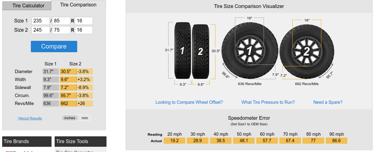
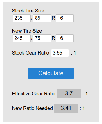
Yeah using general speak being out here it all 32 to 37 inch tires on 3,55 gears and wondering why there truck has excessive EGT's and low MPG's. More common issue that most think here. Now there is members here like @IBMobile that run the 245/75 R16 on 4.10 gears which is way good for towing placing final ratio at 4.28:1 to the ground. Talk about a towing monster.
-
For your setup to get that inch down... I ran this size on my old 1996 Dodge 1500 (Lil' Red) and ran great and increased the MPG's. Lighter rotational mass and less rolling resistance. Here is the alternate wider size which still fits your dually. This is the size I'm running on Beast now and no issues. Great offroad performance and great traction on the ice. So you coming from a 235/85 R16 tire this would give you the 3.70 ratio. The magic tire size that is listed on EVERYONE door tag but no one wants to even use...
-
@JAG1 Yes and no. Yes I love the electronics because there is more precise timing and fuel control over the old mechanical pumps. Even the P7100 pump has no timing advancement at all, which is a static timed pump which is the part why no. Electronics make diagnosing easier being the ECM/PCM provide clues to what has gone wrong. When mechanical system like the 12V you on your own to figure out why your truck doesn't start so now you have to test everything because there is no help from a computer. This is one of the reason I fell in love with the Cummins over my 1972 Dodge I own before. No computers and diagnosing weird ignition issues some times you would miss the actually problem, in one case I had a burned hole through the rotor which you couldn't see. Black plastic... Just keep in mind when there is a error code present typically its going to be electrical in nature typically. There is a few like the P0216 code which is design to measure how long the pump took to advance or retard timing if it can't do it in a small slice of time then the code is thrown. So imagine if you didn't have the electronics and the timing piston froze up in full retard and white smoke was heavy would you know its the VP44, bad injector, etc.? How about if the timing piston froze full advanced and was difficult to start and knocked really loud and very low power would you know the VP44 had a bad timing piston? Most likely not... So electronics are a good thing...
-
Like with drum brakes I always just pull every thing off one at a time and lay it out exactly like it came off in front of the axle. Then one by one replace parts by matching parts up and then putting them back together the way the came off. Another example is when I do injectors on a 3rd gen you need to pull all the exhaust rockers off. To save time and trouble I lay each rocker out on a rag cover board in the exact order they were in the engine this way you don't have to readjust the lash on assembly. Typically I check them but always within the wide Cummins lash specification.
-
If one doesn't know something someone else will I'll admit freely I don't know everything.


