Mopar1973Man
Owner
-
Joined
-
Last visited
Everything posted by Mopar1973Man
-
Currently watch graduation for @Honey Badger youngest son.

-
All the places I listed are about 6,000 foot elevation comparing to Mono Village which is 7,500 feet. More back country and less limitations like Mono Village. You can ride ATVs etc.
-
What do you expect from me? I built everything on Beast for longevity. This is why ball joint issues are not present. Brakes last long time because with the exhaust brake i rarely use my brake pedal. 445k miles and still rolling. Even today in Everett, WA. Heck I just did the trip to Cally with @IBMobile and @JAG1.
-
I used AC Delco ball joints and still going. Still good. Drilled and slotted tend to crack more often being the slots and drilled holes make it weaker. Best bet is a exhaust brake I go 250k miles on a set of brakes.
-
Use a GPS to track mileage. Error correction math never works. Better yet to have the ABS corrected for proper speed and odometer.
-
There is Goose Lake (outside of McCall) you camp alone the lake edge. There is Upper Payette Lake (outside of McCall) you can camp for a small fee. Hazard Lake is a bit more advanced for travel. About 25 miles back on dirt road is Hazard Lake (outside of McCall). The road is rough and dusty also you climb in elevation.
-
I remember @cajflynn installed a Hamilton Cam and he said he loved the power change. I don't remember exactly the style of cam.
-
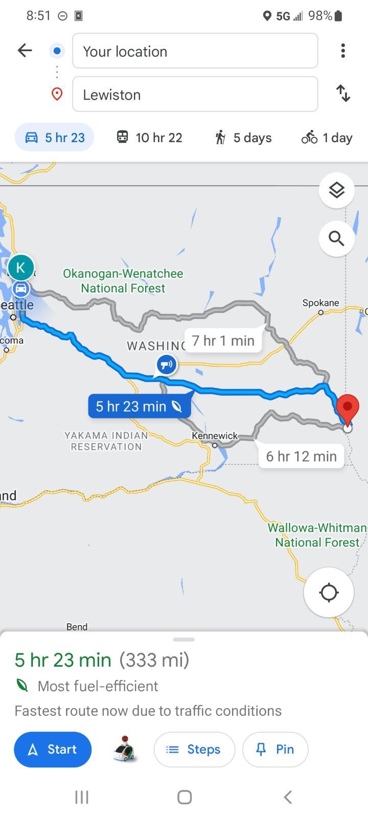
Thanks. Travel has been good. Just getting through Seattle WA sucked it bumper to bumper traffic. Part that sucks my left foot I bruised or something before the trip and man after getting through Seattle my foot is killing me now working that Valair dual disk. Truck used just bit more than 1/2 a tank going from Lewiston ID to Everett WA
-
@Honey Badger and I made a road trip to Everett WA to see her youngest son graduate. Just a wild experience is to be heading down I90 west. I just barely seen the dust cloud and a pickup hit the center median. Then a tire was bouncing down across said median into the road coming towards last second managed to just miss it. I've seen plenty of youtube videos but to actually see this happen is unreal.
-
I would do the testing for either the P0237 or P0238 codes. Basically the test would verify the wire from sensor to ECM for all three wires (+5, sensor, GND). The the next test is wire to ground. It should show infinite ohms or (open connection). Your also going to verify the 5V signal and verify its correct value of 5.00 Volts. The ground signal has to be verified be sure there is something to bias the signal from ground. If that all passes with flying colors then the sensor or the ECM is to blame. The sensor uses the 5V and variable voltage with ground bias. Either the sensor is lazy and failed within specs or the ECM is not sensing the voltage correctly.
-
I would guesstimate about 800 foot pounds at the flywheel being conservative.
-
That looks good. Damn I need to have my trucks both done. @Sycostang67 what did it run you for that?
-
I've been using Hawthorne Berry at 520mg capsules.
-
Holy chit... that is and exact copy of my 1973 Dodge Charger SE I owned. Hence the name of the website.
-
Be careful going too tight you could burn a valve or seat. I did 8 and 18 before and caused stalling issues. Injectors might have a say too depending on pop pressure too. Be careful going too tight you could burn a valve or seat. I did 8 and 18 before and caused stalling issues. Injectors might have a say too depending on pop pressure too.
-
99% of all filters will do just fine. Just Fram is a no-no.
-
Wix are good filters as well. As many logging trucks out here running NAPA / Wix filters I would say they are suitable for use on the Cummins engine. I'm at 444k miles still rolling.
-
If you look at the Dodge FSM it does list out lash limits for the 24V engines. You should see 3rd Gen lash numbers. IIRC it's 0.026 for exhaust.
-
Donaldson is a good filter but I've been using NAPA for years. For the AirDog I've been getting Donaldson from @dieselautopower. For oil just a NAPA Gold. Stock fuel filter I've been using NAPA Extra Guard (7um filter). Air Filter I get BHAF from @dieselautopower.
-
I've seen even aftermarket wheels crack and fail. Aluminum wheels are not very strong when dealing with lots of weight and rough roughs like out here the back country roads will beat up wheels quickly. Steel wheel hold up much much long without bead leaks and cracking issues. You might add a few pounds of rotational mass but over all life span will out run any aluminum wheels. @JAG1 I'm sorry you have a problem with color... If you look at the animal kingdom the males always have the flashy colors and females are typically rather plain. So why is it that humans woman are flashy and males are bland? Hmmm... Just think about it...

-
I'm running the stock steel/chrome wheels from factory and fit the 245/75 R16 like a glove. No outward offset to sling mud and slush on the side windows. As seen in my signature pic. MUCH stronger that alloy wheels which my factory wheels cracked after 200k miles. The other problem was road salt ate into the aluminum as well. Aluminum wheels out here are very known for bead leaks and the local tires shop deals with way too much. Steel wheels no issues and seem to hold up MUCH longer without issues.
-
Jumping out of gear is because of bad bearings on the main shaft. As torque is applied to the shaft it moves and kicks the stick out of gear. Basically most likely using too thin of fluid and allowing it to overheat. Max trans temp should be no higher than 220°F. Yes you should install a trans temp gauge but do not install fast coolers because it moves the temp sensor too far from the gears and will show cooler. But the fluid around the gears is still hot.Temp sensor must be as close as possible to the gear teeth for proper temp measurement. Mine I bung close as possible to the PTO gear. I've seen my last trans over 240°F towing my RV to Pittsburg Landing near Oregon. I was only running 15 MPH on dirt road running 7% grade. Even my heat shield in place. Even running downhill didn't cool because of reverse torque running down hill. This is why trans temp is required and why fast cooler should not be used.
-
You could just check it in a week or so. Remember... Intake set to 0.010 (0.006 to 0.015 allowed) Exhaust set to 0.020 (0.015 to 0.030 allowed) So quick check is pretty fast.
-
Thanks for the chat on the phone hopefully it answers your questions.
-
Biggest thing is finding the right offset. I did modular mags but the offset was wrong so about 1 inch of tire hung out of the wheel wells. This is bad being driving in snow or rain it slung mud and debris up the side window to the point you can't see the mirror any more. Be aware most cool looking aluminum wheels are typically for wide tires. My problem is trying to find wheels that look cool but keep my 245/75 R16 I'm using a narrow stock steel wheels. Bit heavier but not likely to crack like aluminum wheels did to me.