


Tractorman
Yearly Subscription
-
Joined
-
Last visited
Everything posted by Tractorman
-
@Mopar1973Man , maybe you can assist here. Please review this thread and give us your thoughts. Symptoms are: engine idles fine, or jumps to 1,400 rpm when the throttle is slowly pressed. Engine rpm doesn't change while depressing throttle further. Engine has the following DTC's: P 1693 is a companion code - no concern. P0122 - Accelerator Pedal Position Sensor Signal Voltage Too Low P1689 - No Communication Between ECM & Injection Pump Module ECM and PCM has been checked by Auto Computer Specialists. Scanner show that APPS signal is 0% at idle and ramps smoothly through the throttle application range. @CH123 , please make any corrections if I misstated something. John
-
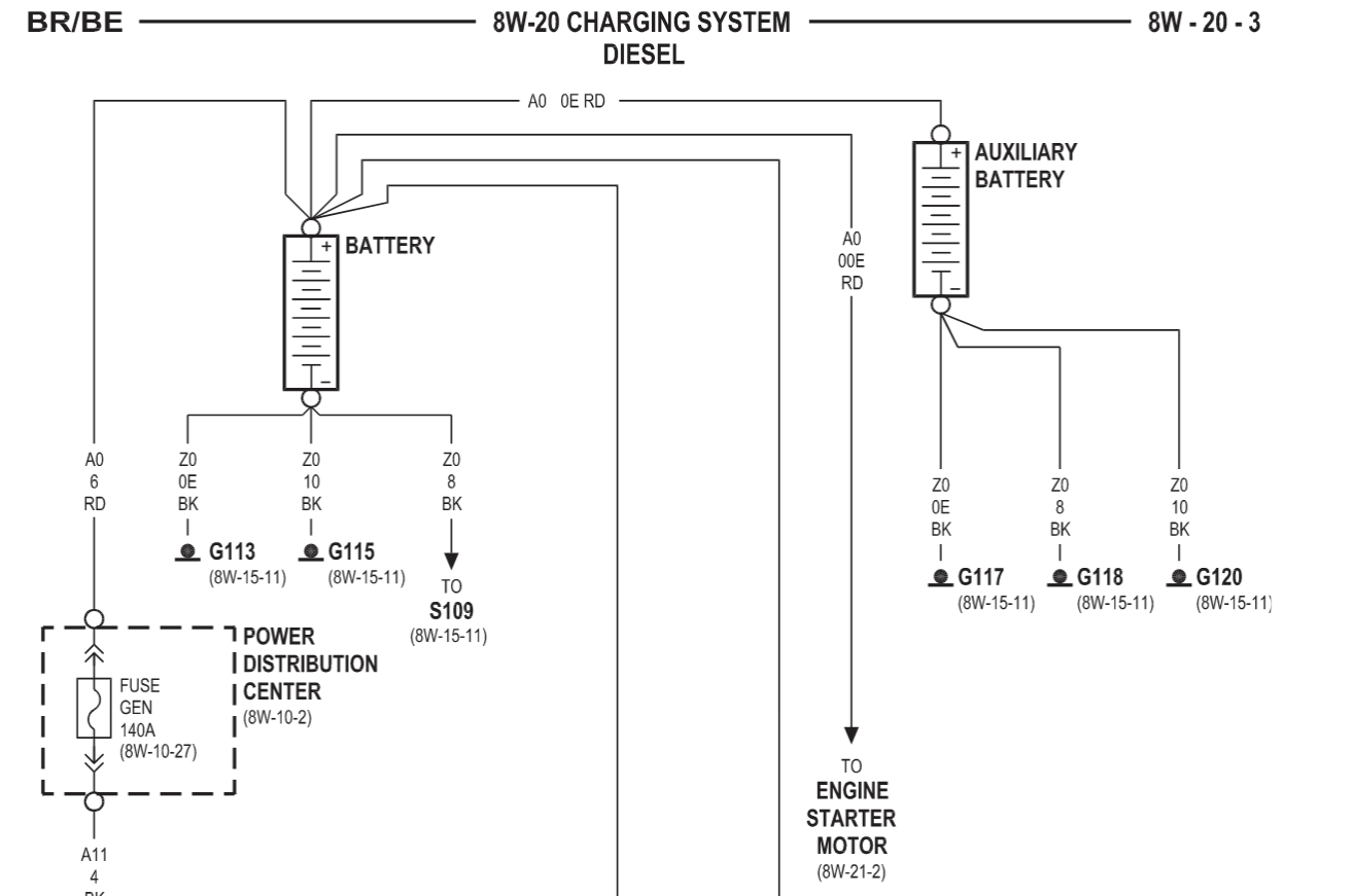
Hope this helps for battery wire sizes. John
-
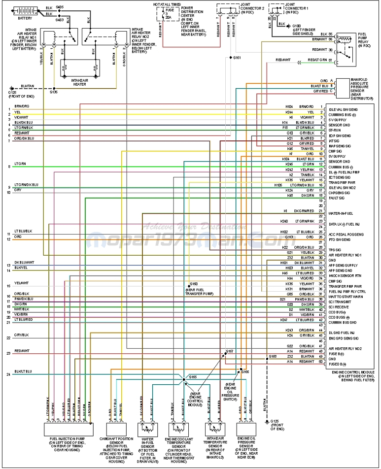
I watched your video - good video. I noticed that as you depressed the accelerator pedal that the accelerator pedal traveled a more than normal distance to get a change in engine rpm, and that the change was sudden (jumped to 1,400 rpm). The idle validation switch is built into the APPS sensor. It appears to be working as the engine idles as it should. Do you have, or have access to a scanner that can read the APPS signal? If so, this could help diagnose whether or not the per cent of APPS signal follows the travel of the accelerator pedal. It could also show an abrupt signal change that times with the sudden rpm change when depressing the throttle. This test could help to determine if the APPS sensor should be replaced. APPS / ECM circuit is shown below: John
-
The ECM controls engine idle - all other sensors (including the APPS) are out of the loop when the engine is idling. However, you do need to make sure that the APPS is adjusted properly and that the idle validation switch is energized in order for the ECM to command engine idle. Since you have a code for the APPS (signal voltage too low), I would address this circuit first. John
-
If you clear the codes, do they come right back? If so, which ones? P 1693 is a companion code - no concern. P0122 - Accelerator Pedal Position Sensor Signal Voltage Too Low P1689 - No Communication Between ECM & Injection Pump Module P1689 - not good. John
-
No need to insulate lines. The AC system on these truck cool very adequately. Likely, there is something not right with your system. If you install the heater core shutoff valves and the the AC works much better, then you probably have a blend door problem - either with door seal leakage or the blend door is not operating to its full travel limits, thus some of the circulating air is still being passed through the heater core. I have a heater core shutoff valve that I use in the hottest part of the summer. The difference is really unnoticeable when the truck is parked inside and used for the first time on a hot day. However, after being parked in the sun for a couple of hours or more, there is a faster cool down because the heater core has not heat soaked the dash, and when engine is started, there is no hot coolant entering the heater core to conduct into the cabin. This is when there seems to be the best benefit to using a heater core shutoff valve. John
-
Sounds like a good plan. Thanks for the informative response - good information. John
-
Glad to hear that you didn't have the battery connected during the tests. I am referring back to your original post as a starting point. Has anyone checked for codes? If so, what are they? If codes have been checked and there are no codes, there are other things to be checked off the list, such as: Did you fuel the truck just before this incident occurred? (possible water contamination or wrong fuel) Have you verified lift pump pressure? Is the lift pump running? The lift pump should run for 1/4 second with key in Run position. Switch key to Off position and then to Bump Starter position (don't start the engine) and let the key return to Run position. You should hear the lift pump run for about 20 seconds. Be sure to always turn the key to the Off position before repeating a test. Check over the positive and negative battery cables and connections carefully. Don't forget the crossover cable. Use your 99 wiring diagram to find and check grounds - especially for the ECM, PCM, PDC and the VP44. This will be a good start. Let me know what you find. John
-
I am kind of at a standstill here as I don't know what you are trying to accomplish with your tests on Joint Connector #8. Plus, it appears that you are testing for resistance (ohms), but you are breaking all of the rules mentioned in my previous post, such as leaving everything connected and supplying external power). This is from your original post. A previous post by me explained why this would be normal to have continuity through both the door switch and through the ignition switch under these conditions. This is the next part of the same paragraph from your original post. I am thinking there is no faulty short to track down. So, my question is - why are you focused on these particular wires? And, what are you testing for? Hopefully, we can get this part resolved and move on to the real issue - lack of engine power. John
-
I appreciate your explanation. The "diode check" function is used for checking alternator diodes. The meter itself applies a specific voltage value to the diode being tested in the free-flow direction. The meter displays that value in voltage - example: .650 volts for a good diode. Reverse the polarity and the meter would read OL (out of voltage limit). Also, it is worth noting that at least one end of the diode is removed from the circuit during the test, otherwise an erroneous reading or damage to the meter (if external power is supplied) may result. Since you were using your meter's diode test function under various uncontrolled conditions (batteries disconnected, batteries connected, engine running, etc.), you were likely collecting many erroneous readings and also you risked damaging your multimeter. The "resistance" test (Ohms) is used for checking continuity in wiring. The meter applies a specific voltage (similar to the "diode check") and measures the resistance of the circuit being tested. The meter displays the resulting value in Ohms. As in diode testing (and for the same reasons), the wire being tested must have at least one end removed from the circuit being tested and have NO external power applied. Don't rely on the meter's "tone sound" for testing results. Look at the display and note the actual ohm reading. There are three tests that can be performed. One test will check the continuity of wire (should be almost zero ohms). Another test will check for continuity of the wire to a good ground source - a short circuit - (should be OL). The last test will check for continuity of the wire to any adjacent wire of your choice - a short circuit - (should be OL). Prior to performing any continuity testing, always do the following: Set the meter to the lowest ohms scale - do not use the Kilo-ohms or Mega-ohms scale. Do not use auto scaling. Touch and hold your test leads together to prove that the meter and your test leads are performing properly. A reading of zero or near zero ohms is expected. So, hopefully you will re-think how you do your future continuity testing. If you still believe that you have a short-to-ground issue, then be deliberate and test circuits that are relevant to prove whether or not the particular circuit is functioning properly. I'll be happy to help you through that. John
-
I can't answer that question as I don't know the purpose of that connector, or what you were trying to figure out with the method of testing you performed. If you don't know what is on either end of the connector, then any values from electrical tests performed are meaningless. Please answer this question - why do you think you have a short to ground in the wiring on your truck? What is drawing you to this conclusion? You may have a valid reason - I am just not getting it. Also, why are you using the "diode check" function on your meter to check for ground continuity (or shorts to ground) instead of using the resistance / ohms function? If you can clear some of this up, then we can move on to trying to figure out the "no power" situation. John
-
Your meter is set to "diode check" which means that current will flow only one way after it overcomes .6 volt. Current will not flow in the other direction. The continuity will be there with the ignition switch turned on for the same reason the continuity was there when the door was open. All it takes is one circuit to be activated with the ignition switch on to make continuity - for example, instrument panel indicator lamps. This would be normal. Am I missing something here? Why do you think you have a short to ground problem? John
-
Before I can offer any help, I have some questions first. Was your meter on the continuity (ohms) setting? Were the batteries connected or disconnected? If the meter was set for continuity (ohms) and the batteries were disconnected, then it would be normal to have continuity between the positive cable and the ground cable when the door switch was activated. The current would be passing through the dome light and through the switch. If the above paragraph doesn't represent what you observed, pleas let me know. Can you provide more detail as to why you think you have a ground problem John
-
I don't think your truck is burning up crank sensors, I think that the after-market crank sensors are of low quality. Many others have reported the same issue with after-market crank sensors. Good to hear that your are making headway, though. John
-
I have done the same. Can't remember the details, but I think you have to slide the seat bottom to certain positions to access four bolts (or nuts), but it is an easy task. John
-
Sounds like you are gaining ground. If I'm understanding correctly, the engine is performing well, but you are still getting voltage fluctuations? Any codes? John
-
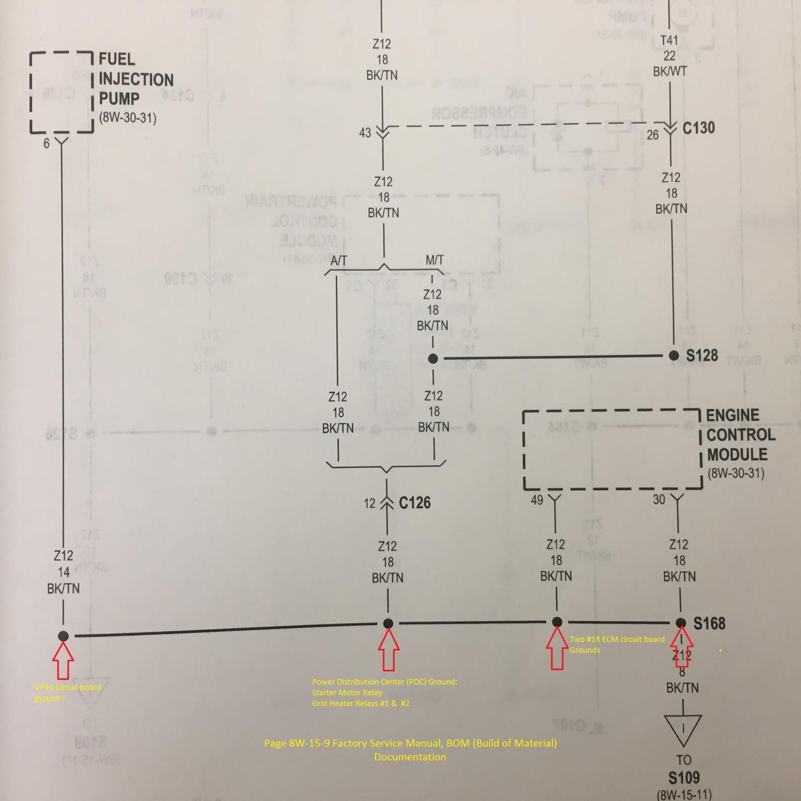
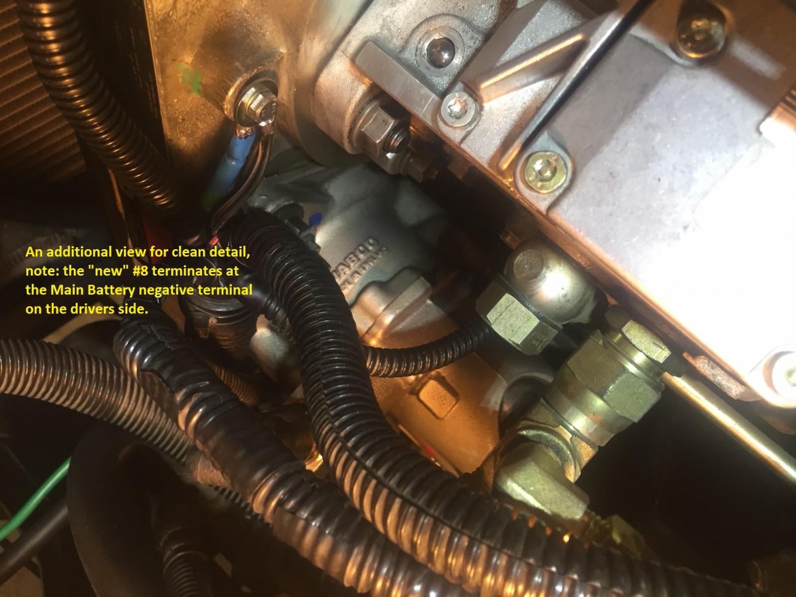
You wrote, "I've decided to do some upgrades to my cables & connections before digging any deeper. Marine grade battery terminals should be in tomorrow." Good plan! Are you referring to ground splice 168 (top photo below)? If you are, then the W-T ground mod wasn't complete. This splice is disassembled and all wires are routed to the front gear case cover with an additional wire to driver side battery ground (see bottom photo). John
-
Also, keep in mind that just because an electrical connection is tight doesn't mean that the electrical connection is good. Tight terminals can be oxidized or corroded leading to a poor electrical connection - all hidden from sight. John
-
@Chickendog73 , how old are your batteries, and are they in good condition? How about the crossover cable? John
-
Good documentation on your part for your initial post regarding this problem. You definitely need to figure this out - you have a good truck with low miles. I don't know if you have a good wiring diagram for the engine controls, so I am posting a diagram below. I suspect that the collision with the rock wall is related to your symptoms. A couple of questions, though: Did the "stutter" show up right after the collision, or after the VP44 replacement? How much time and miles elapsed between the collision and the VP44 replacement? You mention testing the red / white wire from the PDC - I am assuming this is the wire that supplies power to the ECM and the injection pump. If so, I would continue to check voltage (engine running and voltage spikes occurring) downstream from there. As you can see in the wiring diagram, Joint Connector #2 (inside the PDC) and Splice #161 are part of that circuit. I would also verify the condition of ground Splice 168 to Ground 125 on front of engine. If you are using another ground connection point with your test lead and there is truly a ground problem in the ECM / injection pump circuit ground, you will get a steady voltage reading because you are bypassing the potential ground fault. Also, I believe there is one more splice that is not shown in the diagram - that would be S109 that is between S168 and G125. Are you familiar with the W-T ground reference modification? If so, has it been done? John
-
You can just swap out another like fuse and another relay and go for a quick test drive. John
-
There is a single connector with two black wires that are connected to the positive post of the driver side battery. These wires supply power to the intake manifold heaters (grid heaters). Within a few inches of the battery connection, you will see two fusible links - no fuses. Disconnect the the single wire connection. There are two fuse group locations. One is called the Power Distribution Panel (PDC), and the other is called the Junction Block. The PDC is located right beside the driver side battery. Th Junction Block is located on the left end of the dash. The driver's door must remain open for access. Hope this helps. John
-
Sounds like you are on the right track. The intake manifold heaters draw about 100 amps each - there are two of them. They are automatically in operation below 60°F ambient temperature. With the key on, engine off, the heaters are on while the "Wait to Start" lamp is lit. After the engine is started, the heaters post-cycle until a specific engine operating temperature is reached, or the vehicle speed reaches approximately 25 mph. The post-cycling current is higher than the alternator output, so it is normal to see the dash voltmeter drop significantly. This is why I recommend disconnecting the intake manifold heaters while diagnosing a low voltage electrical problem. John
-
I would be looking into this before doing any parts replacing. Was the intake manifold heater post-cycling when you were seeing the voltage drop on your test drive. If you are not certain, then I recommend to disconnect the intake manifold heater to simply troubleshooting the voltage drop. In normal operation, when the manifold heaters have finished their post-cycling, the voltage powering the VP44 should be steady around the 13.5 - 14.2 volt range. Steady is the key word. If the voltage continues to fluctuate wildly at the VP44, then you should check the power supply to the VP44, ECM and the PCM; but more importantly you should check that you have good operating ground circuits. John
-
I agree. John


