Mopar1973Man
Owner
-
Joined
-
Last visited
Everything posted by Mopar1973Man
-
good guess is that the fuel line being 3/8 of inch gave less to modify in the way of fuel system where 1/2" line is only good if you got 1/2" pickup to 1/2" plumbing throughout the system... But that just a simple guess though...
-
Dang it... Working right along this morning and without warning the computer hung itself which is really weird... But Hit the reset button and the BIOS instantly reported that my 4th hard drive 500 GB just tripped SMART and has gone BAD. So I tried to deal with it and test the drive but when I got it booted up the drive is gone... :cry:So now I got to call me dealer and see about getting a new drive...
-
Duh?!?! Climate change... :ahhh:Climate is always changing that why they call it "Seasons!" Spring, Summer Fall, Winter... :banghead:I wish they quit trying to BS a BS artist...
-
OMG... But it would work...
-
Well the shop that did mine had a collar that went over the injector and tighten up against the fuel feed... But still in all if there is a deformation in the injector it should leak on the test bench too... Because the test bench simlates the connector tube as well... If there is cracks in the body too it should show up...
-
Like myself climbing some of the dirt forestry roads at 8-12% grade you can get some good pyro temps. I typical hit my wall at about 1,000*F worth of pyro climbing grades. Hovering at about 18-22 PSI of boost. I've maxed out a few times at 1,400*F but just short burst passing people. Typical highway cruising empty I'm floating 450-600*F worth of pyro at about 1-2 PSI of boost at about 55 MPH... But kick it up to 65 MPH the pyro floats 700-800*F and boost is about 6-7 PSI now... Just for 10 MPH gain...
-
Darn you all... I've been enjoying my mild winter now this morning its 28*F outside and frosty... Come on global warming (Spring!)
-
Might try with the vendors here... Several good options...
-
The pressure from the filter to the VP44 through all the lines will be the same... If you mount the gauge on the VP44, or the output of the filter... All the pressure should be the same...
-
Should come to Idaho... We had a very mild winter... Little snow but temps floating in the 32*F-48*F for the past 2 months... But you guys are getting what we had last winter...
-
That's bad CajFlynn... But in any case all you got to monitor is oil usage and the blow by... If you not losing oil and the blow by is minimal... Then keep going... Diesel engines are not like the gasoline cousins... Since the cylinders always have pressure on them the don't normally consume oil through the rings but the tend to push crankcase gasses past the rings. Hence why you monitor the blow by. If you want to validate it easy do a compression test to verify the condition of the cylinders...
-
Share the wealth...
-
Pull it out and have it pop tested and see if it leaks on the test bench...
-
Very funny... But here is the notice from Vbulletin...
-
Here is how to bleed it out... http://mopar.mopar1973man.com/cummins/2ndgen24v/clutch-hyd/clutch-hyd.htm No... The reservoir is re-used... Just pull the hose off gently...
-
Why so early? Geez... That got to cost a bunch... Even when the dealer did the first few changes I done them as suggested at 6K miles... After 30K miles I was doing them at 7.5K miles then once I added the Frantz Filter I went to 10K miles... Here is the maintenance schedule from the Dodge FSM... http://mopar.mopar1973man.com/cummins/2ndgen24v/maintenance/maintenance.htm Then here is the write up on Frantz... http://mopar.mopar1973man.com/personal/2002/frantz-filter/frantz-filter.htm Talk to Dorkweed he hasn't change oil in 70K miles now... Using WalMart Unverisal 15W-40 and a MotorGuard Filter (simular to Frantz Filter)... Been testing his oil through Blackstone Labs and still passing the grade constantly... http://www.blackstone-labs.com/
-
The test port is fine don't worry about it... The gauge will show proper pressure...
-
Hang in there there is a update (4.0.2) coming soon... I'm stuck waiting still till the end of next week...
-
I'm running Chevron Delo 15W-40 and Frantz Filter I change out at 10K miles... Typical oil changes are done at 7,500 miles...
-
Hmmm... One of these days I might wear mine out but so far it still tight... Just keep it greased up good... But are for replacement I've heard that the luke link is the way to go...
-
Took mine off and don't even bother... I rubbed a few holes in mine rather quickly and gave up on it... But when I did have it I just rinsed it off in the sink let it air dry... Still waiting for my filter minder to move...
-
As for the smoke switch... He's right... I would build for power and MPG... The only time I see smoke is on a hard launch... But if I'm mellow about it... It's not bad at all...
-
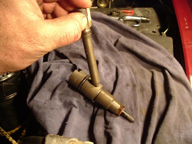
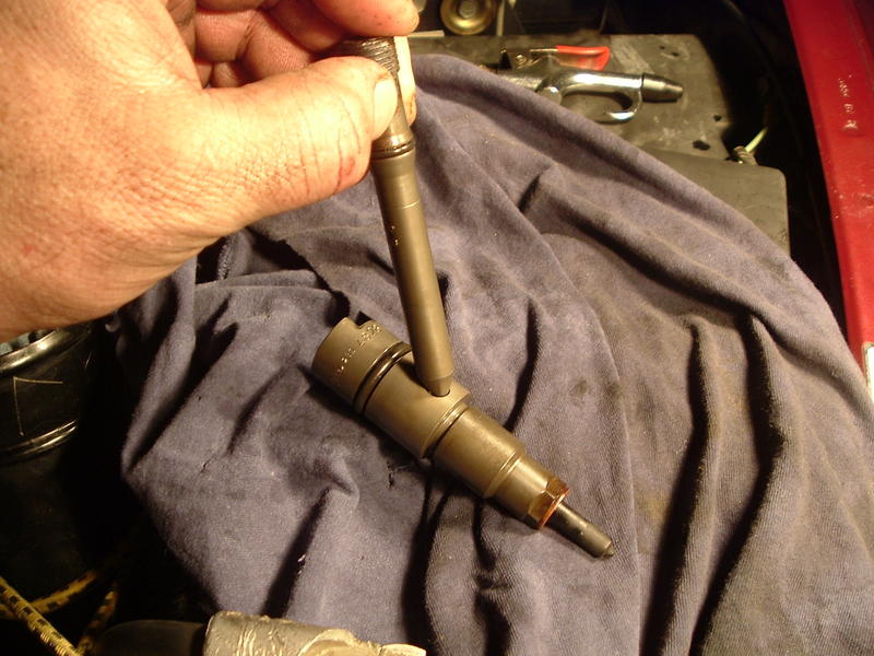
Hmmm... High pressure line to head meets with a flare connection to the connector tube... Then the connector tube meets the injector in the same fashion. So that means there is either a deformation of the one of the joints causing a leak... Or you got debris caught between the joints... Just for crud and giggles would you be will to pop test that injector in #4?... I wonder if the pop pressure is just a bit to high and forcing fuel out... (wild guess!)
-
As for the slave cylinder I say replace it and the master above. You can use NAPA replacements but you need to bleed it down before installing. Yes its installed as a loaded system. As for the driveshaft thats correct...
-
Wow! What a PITA... Change out both the connector tube/o-ring and then the high pressure tube... Ok the other thing I was told to look for is check the body of the injector for damage where the two meet. Which your thinking the leak if from...