


Haggar
Unpaid Member
-
Joined
-
Last visited
Everything posted by Haggar
-
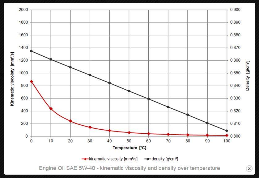
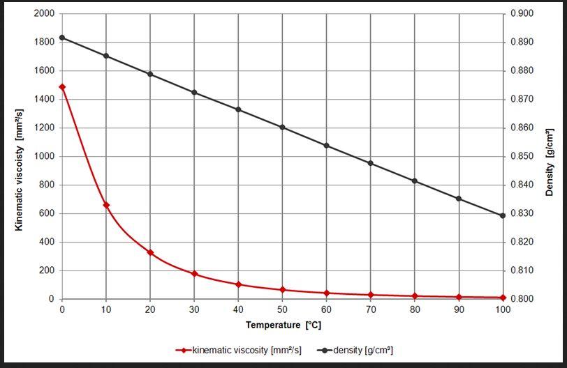
Hex, Here are the viscosity curves for a 15-40w and a 5-40w oil. The red line is what you are interested in. they are mainly different below the 30c (86 F) temperature, and really different below 15C (60F). They mimic each other above that. During winter, if you do a lot of cold starts, you could use the 0 weight and not worry about it when it gets back to normal starting temperatures.
-
There is no PCI bus in our vehicles. Ours is CCD. To try his idea, you short the two CCDs together. (notice CCD or PCI in his test). HTH Hag
-
Junk, Sorry I am behind on this hope you have it already! I was going to suggest dropping the spiders, but when I saw that it was a roll pin, I was unsure if it could be done. (If there was enough room for it to come out.) It appears that there is enough room. Good punches and hammers. You can also try to move it either direction first. The whole trick is to get it to move without distorting the end of the roll pin. Get good punches!!! keep them burr free too! There could be a burr that is keeping you from getting it moving.... You may have to get the truck higher, so you can sit to swing at it, or can you use a long bar and someone outside the truck swing while you guide it? I am in a similar situation with my brothers 01. having trouble getting the pinion bearing races out of the housing.... Shouldn't be a fight, but it is for some reason.... GL Hag
-
JHF, Thanks for the link. Step 5 exactly "100 ohms" is not important. The reason is: You have both ends of the wire disconnected. You are then testing that wire to ground, looking for a short in the wiring. When they say "greater than 100 ohms" this goes to infinity and even open circuit. (it should be an "open circuit" That wire should not go to ground anywhere.) the technical writer was trying to compensate for technicians with poor troubleshooting skills, improper meter set up etc. It looks like in an earlier post you say you read (with ECM disconnected and relay removed) from the socket for pin 85 to ground less than 100 ohms. (you have shown a couple different readings there.) This is a big part of the problem. (My meter reads O.L. when the leads are not touching.) with relay removed and ECM disconnected when you measure from cavity for 86 with the red lead, and the black lead on the negative battery terminal you should see O.L. or whatever your meter reads with the leads not touching anything. The brown/white wire should NOT be touching ground anywhere.... If you see any other reading than O.L. it is touching ground and is wrong. (you will find the insulation on the wire is rubbed through somewhere.) HTH Hag
-
Dave, The copper was too hard. Happens a lot with steam systems. ( the copper should be dead soft and pure, but copper is expensive so they add tin, aluminum, zinc.... and they don't anneal it after the work hardening....) You can soften the copper/bronze washers. heat them with a propane torch carefully until red. drop them in cold water. this will soften them. (yes it sounds odd (it is opposite carbon steel), but I can go into why if you want...) HTH Hag
-
DF!!!! This sentence made my day!!! I lost a whole cup of coffee! (most on the monitor, some in the lap...) This is past the 6 degrees of separation... so were you the friend? did you know him? lol I am still laughing! Cheers! Hag
-
JAG, A poor ground causes high resistance. High resistance causes higher than needed amperage flow. high amperage flow causes heat. The contacts in the headlight switch have more resistance than a straight piece of wire. So in laymans terms more of the amps are "used" there. This makes heat. Mike has a good point too, the voltage reduction the dimmer gives is a heat source too. Hag
-
JHF, If you were actually checking 86(this is the ECM output to fire the relay) to ground (ignition off.... ignition on would/should blow your meter) you could get a couple different readings. with the relay in the socket, you would read resistance through the coil which should be in the range you said. If you did it with the relay removed, you are reading backwards through the ECM and power supply.... it will be an odd reading. Where did this diagnostic list come from? I can't find it in my manual. I would like to read what/why they are looking for. I have attached the FSM page for the relay. To diagnose this system, I would: 1) remove relay. 2) with the key on, put the black meter lead to ground (a good ground) and put the red in 86. You should have 12v. 3) have someone turn the key off while reading this. The 12v should go away. recycle the key on. it should come back. 4)move the red lead to cavity for 30. This should have 12v whether the key is on or off. 5)make sure key is off. put meter on ohms. touch red and black probes to each other. This should read about 0.1 ohm or so. 6)put black lead on good ground, put red lead in 85. You should have about 0.1ohms or so again. 7) Disconnect the wiring harness from the VP 44. 8) with the black placed in 87. put the red on terminal 7 (red / light green) at the injector pump. this should read 0.1 ohm or so. You have now confirmed that the 1) ECM is outputting 12v when it is supposed to. 2) fuse 3 is ok. 3) the wire between 85 and ground is good. (this will let the relay shift when commanded) 4) the wire between 87 and the injector pump is continuous. The only thing we have not proven is that the VP44 is "seeing" the signal sent. But if all the above checks out, it should be close. The only other test we could do is put the relay back in and check Terminal 7 to see if it gets 12v. but that would require the VP44 be disconnected, and it is possible that will throw other codes. (if needed we will talk about how to set up a back probe.... but that is scary for weather proof type connectors.) HTH Hag 2001 FSM Ram 8w-30-37.pdf
-
Here is the page from the '01 FSM for the C3 DIESEL pinout (gasser pinout is similar but with more gasser specific stuff) . The two big things that jump out there..... That is: data bus communication and the Automatic shutdown relay..... HTH Hag 2001 FSM Ram 8W-80-69.pdf
-
IIRC, The T style is the 98/99 steering. Those are the parts I put on my 01.5. He has "the good stuff" stock. I think we call it HD, but it was probably just the stock stuff then. His being a 98.5 puts him square in the T being installed from the factory.
-
ummm 01 never had the 12v from the factory.... only the 24v.... (why drop back to a 12v instead of p-pumping a 24?) Take a peek at it. could be a nice truck or a major pita. interested in how it was handled PCM, missing ECM. etc etc. one tie rod? Lol Me beat me, but I would like to know the blend of computer systems.... And if those things are not perfect, then everything else might be "just good enough.... to run most times...." HTH Hag
-
Wow, Can you picture trying to get a wedge in that one right behind him? That looks like it would be harder to split than elm or sweet gum.... And drip, no sweat either. Must be that dry heat... Cheers! Hag
-
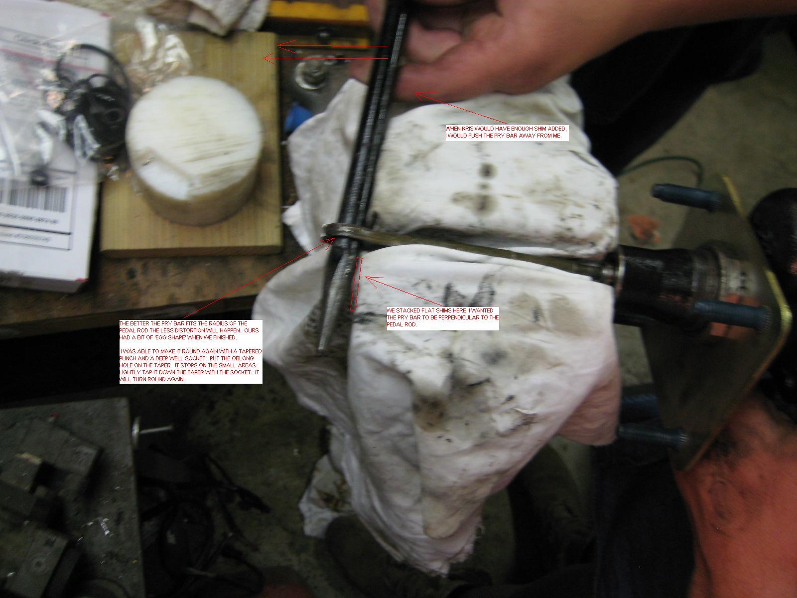
The mind is a terrible thing to waste..... As I was going to sleep last night, I sortof remembered I may have had to grind a bit to relieve stress on the crimp points. Just using a dremel. In none of my pictures do I show this, but for some reason I remember it. I may have had to grind the inside of the staked points to allow assembly without force.... sometimes I wonder why I have a brain at all.... Anyway here are a couple annotated pictures I have. Took me a while to find them.
-
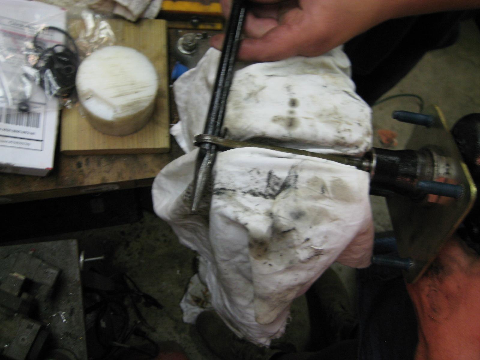
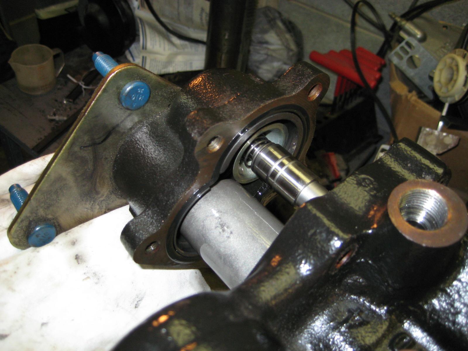
Guys, You don't have to cut the rod.... The staking is very light. I was able to pop it out with a pry bar. Just be careful to not make the rod hole into an eccentric (or make it round again when you put it back....) (I slightly eccentriced mine, just used a big tapered punch (like a spud wrench) to make it round again.) Sorry the pic is not focused well. The rag is covering my vice. I closed the vice to use as a puller, against a shoulder on the input. (I think you will see where it is staked it then goes to a larger diameter.) I used a pry bar that fit the hole in the rod really well, then added shims between the pry bar and vice at the fulcrum, to pull the rod straight out. I am working the pry bar and shims, and my buddy is holding the rest of the hydroboost as I am not clamping it, just using it to pry against. When I put it back together, I just re-staked it slightly with a punch. After it is installed where's it gonna go? (It was staked heavy to live through shipping and assembly.) HTH Hag
-
Also, I know nothing about how Dodge programmed the automatics (don't have one), but GM used "speed" as one variable to define shifting points and load calculations for setting the shift points and TC lockup and such. Just upsizing a bit in the tires on the suburbasaurus resulted in all kinds of troubles with transmission shift points, proper lockup and downshift. So my throttle positions and my "speed" no longer properly matched the equations for the calculations. The computer could not properly compensate for input. So the output was garbage. Correcting the VSSB (in older GMs this is where the speed signal was compensated for tire size and rear axle ratio before being fed to the computer) for the tire diameter change fixed a lot of evils. HTH Hag
-
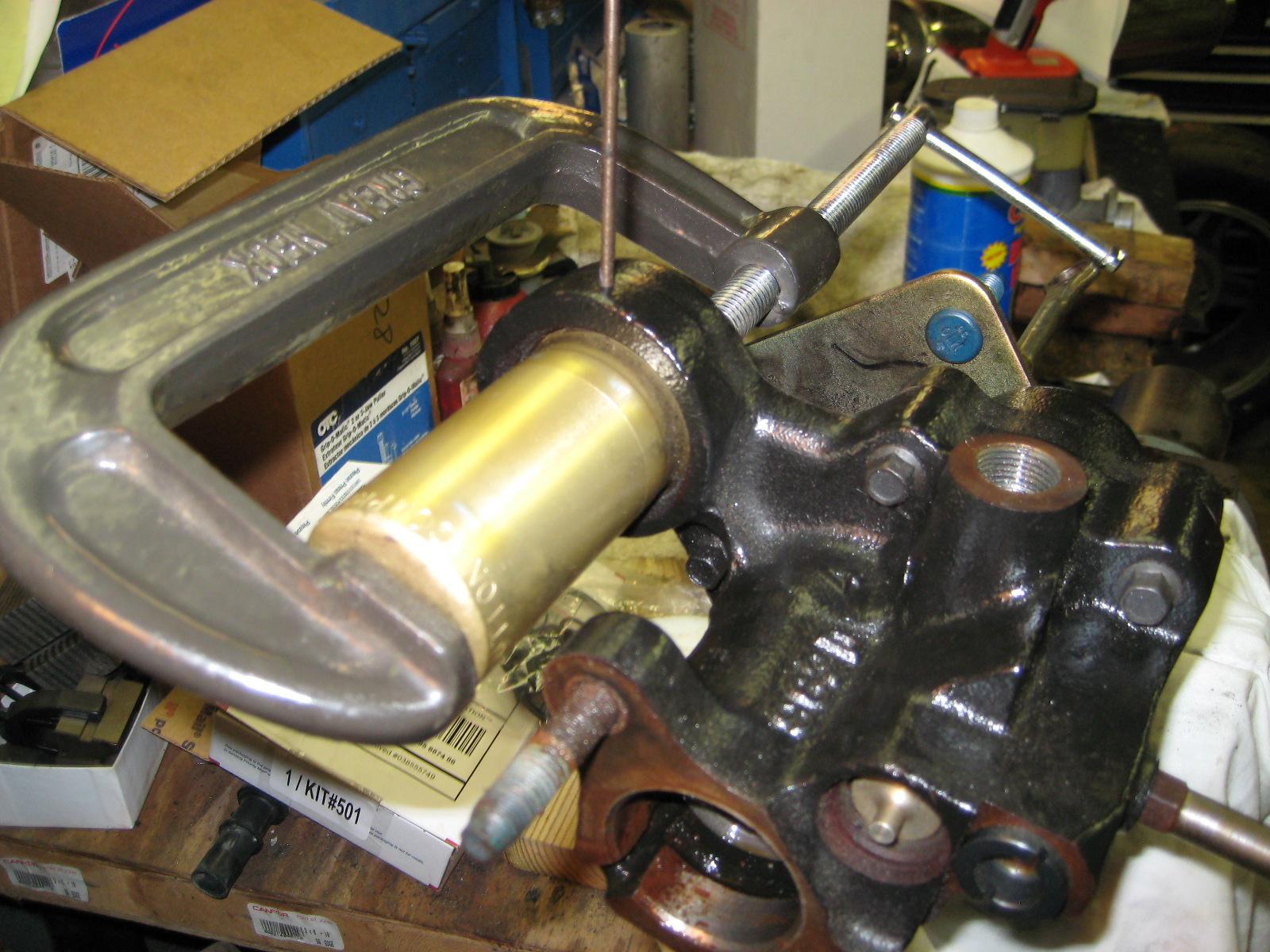
The accumulator is held in place by a heavy snap ring. The accumulator has a heavy spring in it. The C-clamp collapses the accumulator spring to allow you to use the pin hole to push the snap ring and release it. You might be able to do it by hand, but since I only have 2 hands I couldn't manipulate the snap ring.... it takes 3 hands to get the snap ring out by itself. The snap ring is a 330 degree wire, so you push one end down, then hook it with a control screw driver or hooked pick. It will come out. That is the toughest part. The only other curve ball is how the input rod is attached to the back of the power piston.... In many GM applications this was a crimped ball connection... Getting the ball out of the crimp took some time and hand made tools. I think a lot of the Ford and Dodge systems just use a clip or retaining pin. HTH Hag
-
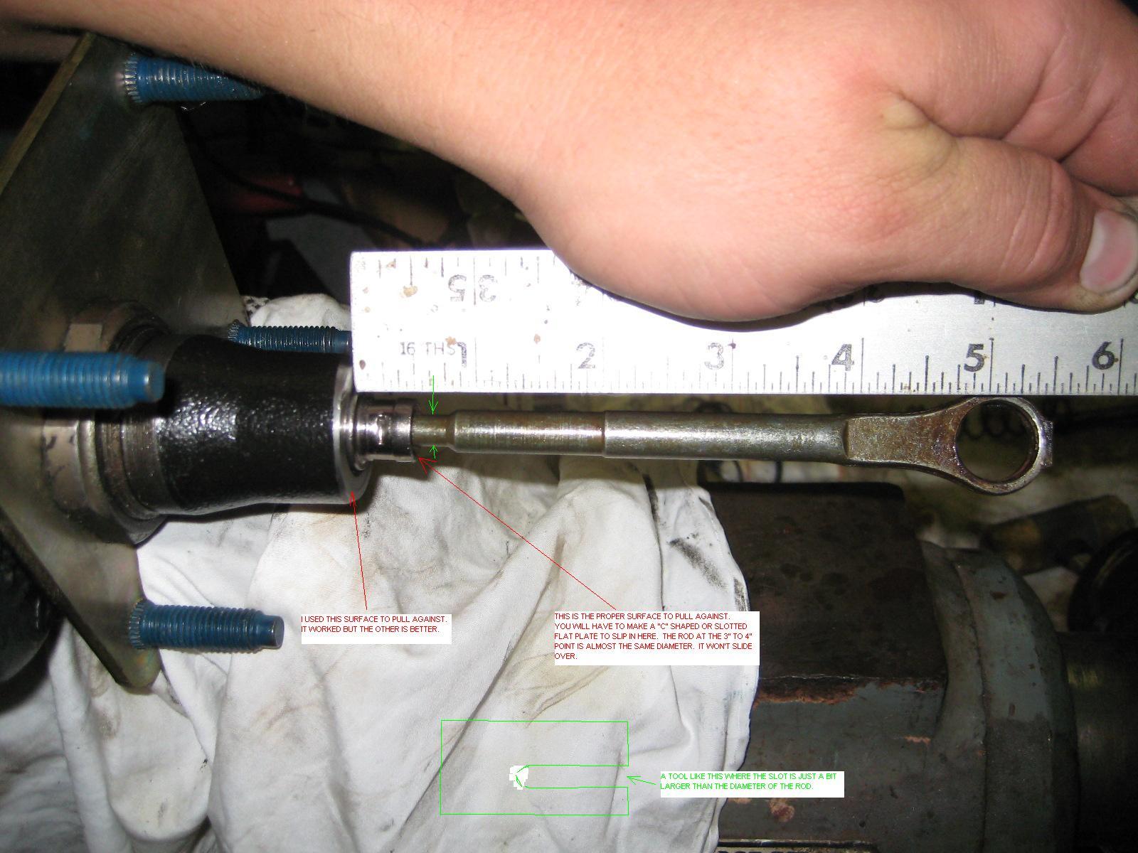
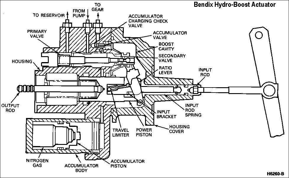
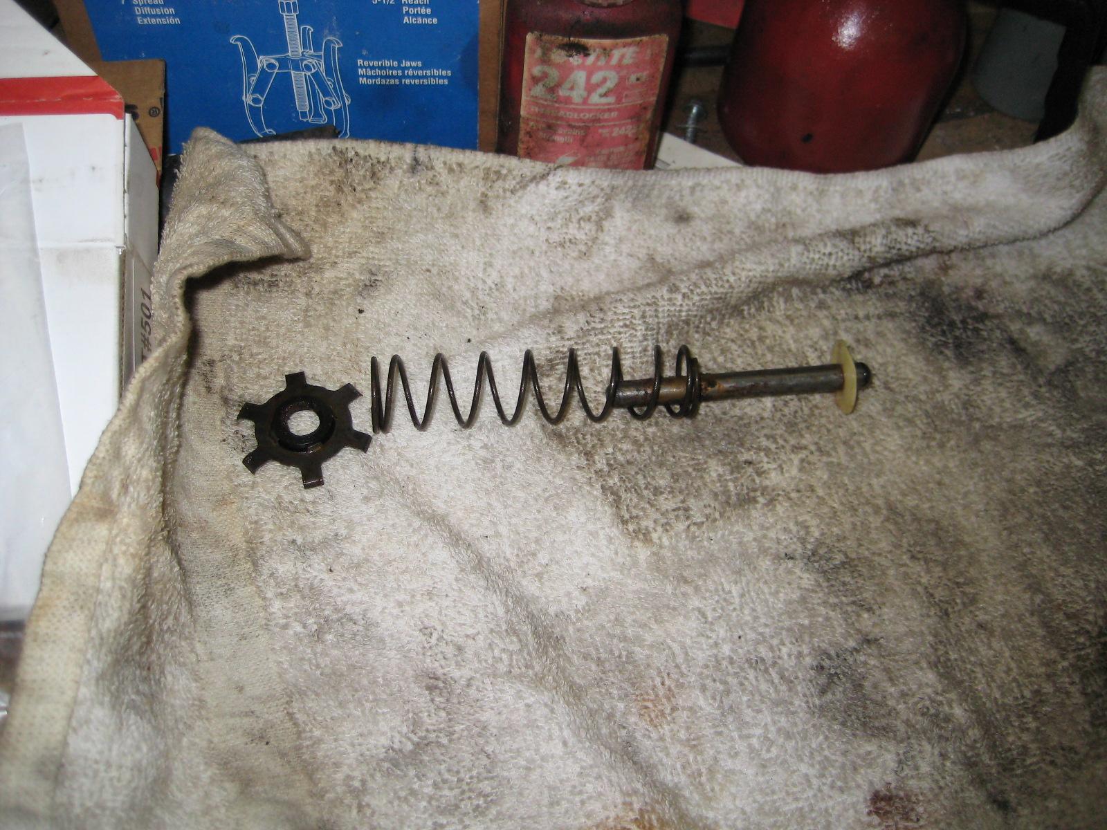
The rod that comes out of the back is what makes the difference for all the different applications.... The rebuild places just rebuild them, they don't know what rod or length you are supposed to have. GM crimped theirs on. All of my pictures are how to "uncrimp it" then put it back so it is the right length. Don't let this fool you. It is amazingly simple inside.... You will kick yourself. The only "worry" is that the accumulator has pressure. Just apply the brakes on the truck 5 or 6 times before you start pulling the unit out. a big C clamp is how you remove the accumulator. Picture of removing the accumulator Here are the two housings coming apart. (previous picture showed you the silver pistons out of the housings) and a picture of the output rod and spring. and a cross section of the assembly, just for giggles.
-
Drip, The booster rebuilds easily. I have some pictures from my rebuild (it was for a GM application so a bit different on pedal end.) I think i got all my parts from these guys and talked with them on the phone. They are in Asheville . http://piratejack.net/installation-videos-helpful-resources/ The two cup seals on the left (in the picture) are what is allowing power steering fluid to leak into the cab..... Hag

-
" ...he got it jb welded and feels pretty confident in his job..." Sorry, but did anyone else spew coffee all over their monitor? Couldn't help it.... it just slipped out. Tell him that made my day!!! hope it lasts forever!! Hag
-
I agree the Donaldson B085011 is listed as a "primary" filter. But looking more closely at the details, it does not meet the old standards of primary secondary filters etc (and the old accepted use of those terms.) The new testing standard is ISO 5011. https://catalog.donaldson.com/productDetail/en/A?R=sku20081834A&productId=11631&skuId=s10132 Looking at this page, the manufacturer claims a 99.9 percent efficiency. When we look more deeply there are two types of test media.... ISO 5011 Fine and ISO 5011 Coarse. (see this page for the two particle size distributions. http://www.particletechnology.com/test-dust) Donaldson does not list which they used. Both samples have particles as small as 1 micron. Just different amounts. (the fine seems to have higher percentages in the lower sizes.), but it works pretty well. I have no conclusion from this information that it could be worse than the stock filter, and significantly better than a K blah blah type. Here is a good article where some guys got together and tested some of the filters available for a duramax. http://www.billswebspace.com/AirFilterTest.htm Notice the reality vs the claims. It is extremely hard to come up with the exact correct numbers. But from what I can see, I feel confident that the filter I use is "good enough" for a mainly on road vehicle, with some off road use, and an operator that understands his vehicle and maintains it properly. Anyway, I run my bhaf without worries. I use differential pressure for when to change. The only thing that i could worry about is water splashing. but I don't run mine in mud bogs etc. I might want to redesign the holder if water splash was more of a concern. just my thoughts. Hag
-
Florin, The reason they don't add properly, I am betting there is a slight angle going onto or off of the scale. This will throw your totals off as the tongue weight shifted slightly because of the angle change. There is also, that looks like a county landfill, scrap yard, or small quary scale. Those are not "usually" calibrated like or as often as dot certified scales. This just says your mileage may vary. I will look for some of my weights. rarely do I get a chance to measure the truck empty. (just not the opportunity to drop the trailer and weigh.) In my mind though I use around 9,500 (or more depending on tools and fuel tanks) for the truck to ball park myself when trying to decide if I can pull and forget, or if I need to use all back roads to and from where I am going... HTH Hag
-
015, most loc tite chemicals are anaeorobic. This means they only harden when they are deprived oxygen. The bottles are designed to allow a bit of ambient air to constantly move through, so they will stay liquid. I have some products that are YEARS old and still liquid. (we will get to whether they work or not in a different thread...) Do not store them in a tupperware container, or a ziplock bag. They need to stay out on a shelf so oxygen can freely migrate into the bottle. Hope that helps. Hag
-
D, Great. The wiring diagram we are using should be valid then. Good luck! Hag
-
Tfaro and OP, I think it is GM that uses a flat bolt and two washers. The lower control arm (LCA) front bolt is made with the washer on one side, the nut side is loose and a different part number. 06505742AA Is the bolt with eccentric washer (16mm diameter) 06505741AA Is the washer for the other side. (16mm diameter) 06505444AA is the normal bolt (16mm) 06102252AA is the nuts (16mm) The upper (UCA)stuff is:(you have to be careful...) 06504989AA is the normal bolt (14mm) 06502698 is the nut 14mm Be careful, there are some trucks that use all the same diameter bolts for lower control arm and upper control arm (14mm I think). Mine uses the 14mm on the upper and 16mm on lower, but I have an 01.5, so very late manufacture. Good luck hope that helps!
-
D, Sorry, being so late to this. Had trouble logging into the website. Great job! Very interesting.... According to the drawings on 8W 42 3 and 8W 42 4. The ground source is G201. it comes through the switch (toward the PCM) and at junction S120 they split apart. What year is your truck? Are we using the correct wiring diagram for yo Both pins 22 and 23 should have switched with the switch. This tells me that there is a wiring problem or there is a wiring problem and a switch problem. ( What year is your truck? Are we using the correct wiring diagram for your system?) Assuming the wiring diagram is correct, If you feel certain that both the high and low pressure switches work properly, ( you could retest pin 22, and disconnect the high and low pressure switch connectors, making sure that the ground reference goes away) you could put a toggle switch in, (connecting ground to pin 23.) this would allow the air conditioning compressor to work. I hope this helps! Hag


