

Leaderboard
-
- All areas
- Events
- Event Comments
- Files
- File Comments
- File Reviews
- Images
- Image Comments
- Image Reviews
- Albums
- Album Comments
- Album Reviews
- Blog Entries
- Blog Comments
- Cummins Articles
- Cummins Article Comments
- Cummins Article Reviews
- Vendors
- Vendor Comments
- Vendor Reviews
- Ads
- Ad Comments
- Ad Reviews
- Policies
- Policy Comments
- Topics
- Posts
-
-

Tractorman
Yearly Subscription6Points1,564Posts -

Stanley
Yearly Subscription2Points566Posts -
Mace
Monthly Subscription1Points68Posts


Popular Content
Showing content with the highest reputation since 02/18/2026 in all areas
-
Here are some threads to peruse that may offer some insight. I have performed both mods about 1 year ago - well worth my time and expense. John2 points
-
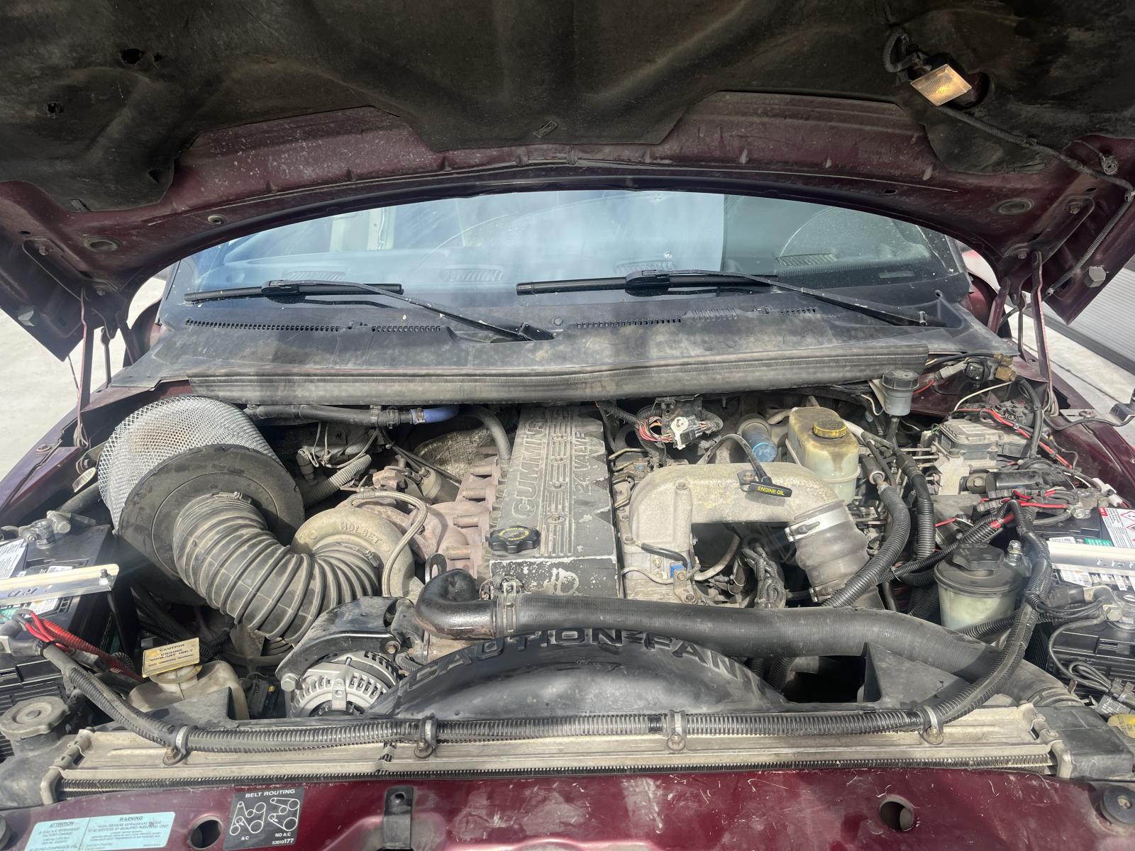
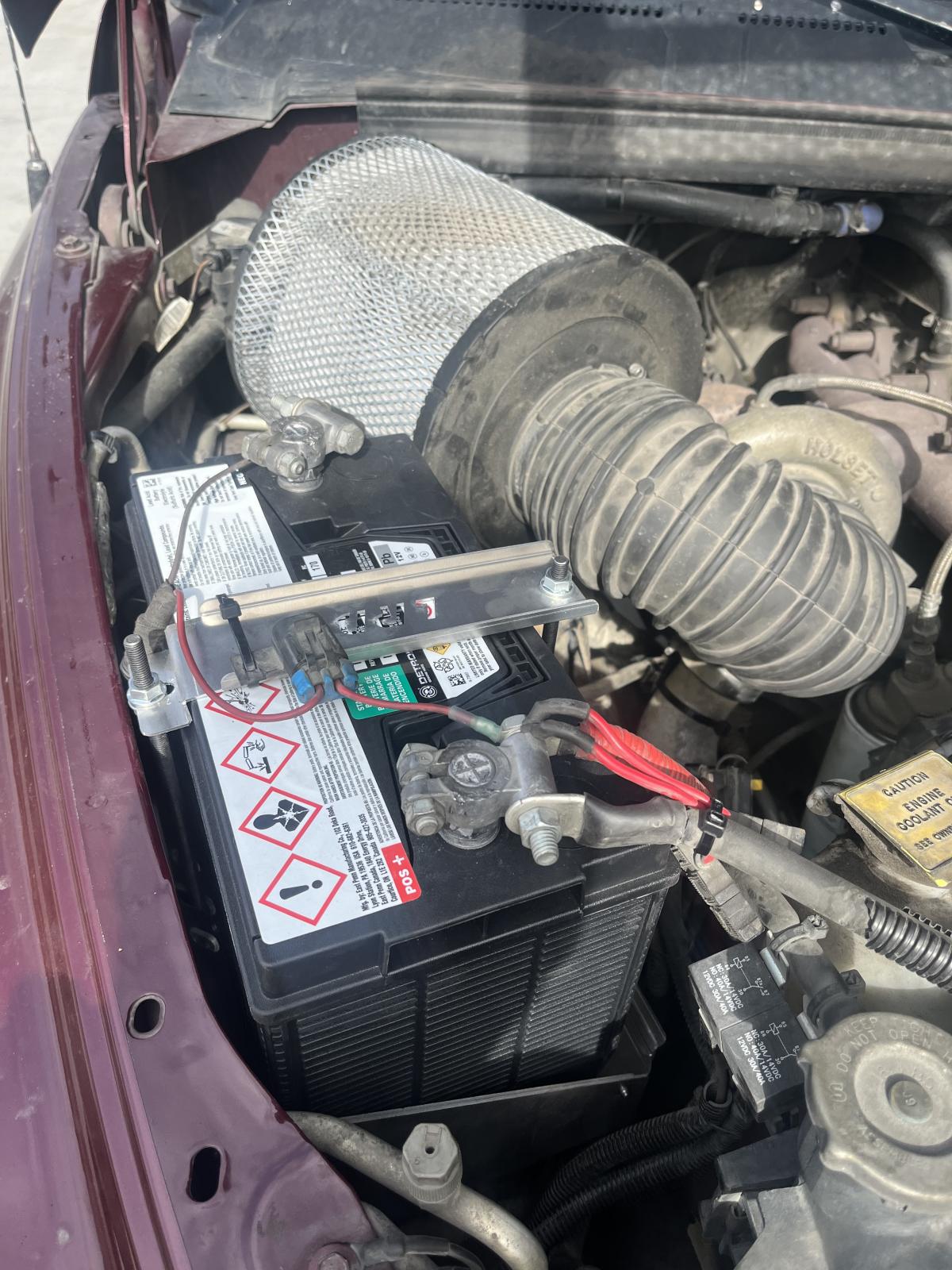
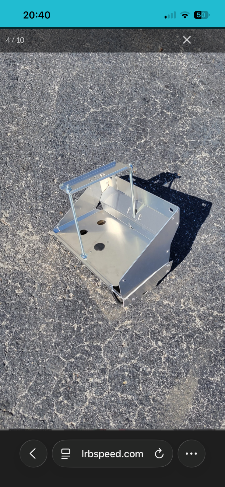
1 pointI read an article here about modifying our existing battery trays to accommodate 31’s. I pondered it but I decided to go another, more expensive route for some reason. LRB Speed makes “put together yourself” aluminum ones for $400. I run 925 CCA Detroit Diesel batteries (from my work) and I’m pretty happy. They’re made well and even a proper spot for the temp sensor on the driver side tray. I had to relocate my horns but other then that they fit and lined up great. With my Nations 180 amp alternator I feel it’s a good combo. My old 27’s were 750 CCA if I remember correctly. This will help with running my Webasto coolant heater I have as well running in cold mornings. Enjoy!
 1 point
 -
1 pointWere you trying to save money on the recycling charge for used coolant? A few years back, I patiently filled my diesel tractor with five gallons of gasoline from a five gallon container. Ya think I should have noticed the vaporous odors of gasoline? - Nope. I started to drive the tractor and noticed that the engine idle was fluctuating. I figured it out and shut down the engine. Fortunately, no harm was done. Stuff happens. I think you are probably okay. I would monitor engine coolant for leaks and periodically check the engine oil condition for moisture. After you have re-established the coolant mixture ratio and the coolant level has stabilized, then monitor the overflow reservoir for normal changes in volume (cold engine vs warm engine).1 point
-
LMC truck has them also. Here ya go. Lmc truck washer res link1 point
-
1 pointThink about your purpose mostly. What is the plan for the truck and what will it be used for the most? Then build this truck for that purpose and enjoy the craft you made! I totally understand why some like the automatics for the stomp and GO! Just one thing to keep in mind, automatics like to have a final ratio closer to 3.73 after tires to reduce the stress on the internal parts. So to make sure you figuring your tires in the part of the design too!1 point
-
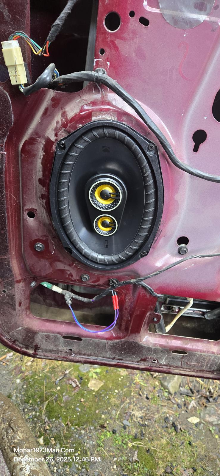
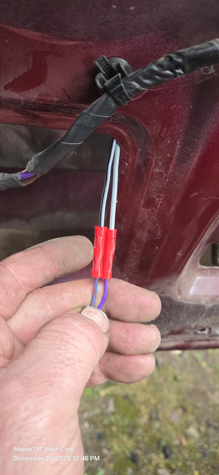
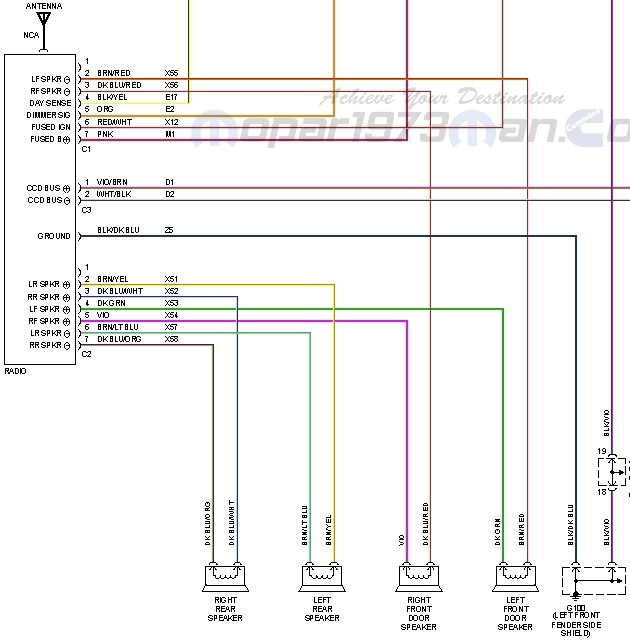
1 pointYup after all the years and miles driven I've had a bad speaker on the passenger side. @Tweety Bird said, "Get this fixed! Time to get new speakers in Beast!" @Tweety Bird and I went to a stereo shop in Lewiston ID to look at speakers and prices. Great quality is really pricey say like $350 for a pair of speakers that really sound rich in frequency. Being budget mined I jumped over to Amazon and found. Kicker Dodge Ram Truck 1994-2011 Speaker Bundle - CS 6x9 coaxial Speakers, and CS 5.25" coaxial Speakers. Yeah Dodge and there strange wiring schemes. I'll list out the positive and negative wiring for each speaker. You can see I cut the factory OEM speaker plug off and wired in the new blade style terminals. Be aware of the polarity of each wire and speaker lug. In this set, the Kicker makes the ground with a black strip, and the positive lug is marked red. Left Front + Dark / Green Left Front - Brown / Red Right Front + Violet Right Front - Dark Blue / Red Left Rear + Brown / Yellow Left Rear - Brown / Light Blue Right Rear + Dark Blue / Orange Right Rear - Dark Blue / White
 1 point
 -
1 pointI love mine I finally got the rear camera mounted at the license plate. Great view and wide angle view as well. Touch screen allows for tipping the camera up or down like you would move your mirror. My setup required both directions of the camera to be flipped, and it works great. Records the GPS location in real time with your video, so position, speed, and direction are all recorded and will display even your road speed of recording, and even if you're talking in the cab. Mirror has voice commands as well.1 point
-
1 pointOne more thing to possibly verify, if you haven't done so already. Temporarily jumper an LED test bulb to the wire at pin #7 at the VP44 (the 12 volt supply from the fuel pump relay). This bulb should always be lit while the engine is operating. If and when the engine dies, note whether or not the bulb stays lit. If it stays lit, then at least you know the wiring and fuel pump relay are working properly. Interesting regarding the reduced frequency of the symptom after adding two-stroke oil. Could be something to it, or just coincidence. You have done a lot of work trying to figure this out, so I personally would not draw any conclusion just yet. John1 point
-
1 pointWeird. I would consider either grabbing a small sample and testing both. Maybe catch the delivery truck and talk to him. See if your state has different policies. Last time I caught Maverik delivery I was able to find how much additives are being added.1 point
-
1 pointFrom the FSM. The torque for the end yoke nut is 470 ft/lbs. John (10) Check bearing rotating torque with an inch pound torque wrench (Fig. 54). Pinion rotating torque should be: • Original Bearings: 1 to 3 N·m (10 to 20 in. lbs.). • New Bearings: 2.8 to 5.1 N·m (25 to 45 in. lbs.). (11) If rotating torque is less than the desired rotating torque, remove the pinion yoke and decrease the thickness of the solid shim pack if greater increase shim pack. Changing the shim pack thick- ness by 0.025 mm (0.001 in.) will change the rotating torque approximately 0.9 N·m (8 in. lbs.).1 point
-
Thank you for the wonderful conversation. Thank you for sharing your story!1 point
-
I will have to take you up that. I thought I had a slight grasp on it before the accident but after with the TBI and my memory loss Im not making head way. Nothing like waking up to that smell...🤮 Possibly, tomorrow might be better. I got this late and were cooking dinner then showers etc and all the fun stuff before bed time. Ill make sure to plan it accordingly, can we do around 6pm tomorrow? My listed phone is fine. Thank you @Tweety Bird for the kind words!1 point
-
1 pointHere is a wonderful display of why I enjoy Ubuntu... Yeah, I'm a CPAP user, and would it be nice to review your own CPAP data here is a good program that worked first try with my Resmed 11 Airsense CPAP. https://www.sleepfiles.com/OSCAR/ They have both Debian and Ubuntu versions.1 point
-
Purchasing a replacement hydrobooster the right way!Beast lost his hydrobooster while my wife and I were down in Boise. While I was down in Boise, I made the call and got a hydrobooster ordered, thinking just direct replacement. Nope! Removal and InstallationSo to remove the hydrobooster your going to need a few tools. Take a 15mm socket deep well and remove the two nuts holding the master cylinder to the hydrobooster. Now carefully capture the rubber seal in the back of the master cylinder too. Pull the master cylinder forward just enough to allow the hydrobooster out. Now remove the 3 pressure lines with a open end 18mm wrench and move those out of the way. The return hose is a spring clamp and just squeeze the clamp and slide back. Pull the hose off. Last step out here to pull the batteries so the brake lights are not burning. Now under the dash locate the rod from the hydrobooster and remive the clip on the pedal pin. This might be a bit tricky but it has tab that laps over the pin to lock and you need to lightly flex it up and over the pin whil pulling the tab. Capture the flat washer on the pin. Noe up in the dash there is 15mm nuts hold the hydrobooster in place deep well sockets are required. The top right hand nut you need to come in from the top there is a passage hole for the socket to fit through. At this point you should be able to remove the hydrobooster carefully. Reassemble in reverse. Just remember to put the fresh o-rings on your pressure hoses so it sealed properly. Be aware...The documents in the box from NAPA are very clear; you need to swap parts from your old unit to make the new unit work. The shaft that pushes the master cylinder, you might have to swap as I did. The new shaft was 10mm too long, which is the brake dragging issue. Then the rubber boot on the input shaft has be pryed off the input shaft collar. Yea! I got that. Then, the adapter plate that mounts the brake reservoir / master cylinder. Rubber boot that goes on the input rod. Approximate length of the rod installed in the new hydrobooster. The master cylinder adapter so the master cylinder will mount! Adapter all on and tight. As for changing the rod that is done by flipping the armed washer like a freeze plug and then work the two arms out of the groove. WARNING: Flying part hazard. The armed washer and the spring will fly so be careful and aware! View full Cummins article1 point
-
1 pointIt will give you time to clear your mind and come up with a good diagnostic approach. Possible issues to keep in mind: intermittent fuel supply blockage, especially suction side of lift pump large amount of air in fuel system (not likely) intermittent power to lift pump faulty lift pump (pressure regulator issue) When things get difficult to diagnose for me, I change tactics and try to prove what is working CORRECTLY, not what is working INCORRECTLY - a process of elimination. This method will sometimes get the issue resolved sooner than focusing on things that one might think is wrong. John1 point
-
1 pointHeck. My wife likes it loud when we travel. Crank up the music for some songs and sing for miles. Then, after awhile the conversation chokes the music out. @Tweety Bird is more of a 70s and 80's fan. I'm more of a popular fan. Truth is, no matter what, we have to travel some serious distances just for supplies. Might as well have Beast in good repair right now being the winter weather is holding up shop work.1 point
-
1 pointSame speakers I put in my truck three years ago. They sound all right. My son says I should put a small base thumper under the seat so that I can "feel the music". Just what I need to go deaf faster.1 point
-
0 pointsNow today I was wiring up the rear speakers and then lost connection on both left speakers.I pulled the front left apart and recrimp the connector solved. Now the left rear is dead no signal. I think a darn mouse chewed the wires in the dash. Ugh! More to come.0 points


This leaderboard is set to Boise/GMT-06:00