


Mopar1973Man
Owner
-
Joined
-
Last visited
Everything posted by Mopar1973Man
-
Actually, its 7 to 12 PSI is an optimal cranking pressure range. Above the 12 PSI, it could produce hard starting because the timing is over advanced during cranking. About a one pulse per second or so. Switching off and on the power to the lift pump. As the FSM calls it a 50% duty cycle. Once the ECM detects idle RPM then the ECM switches to 100% duty cycle for powering the lift pump. Be honest I should replace my relay being its already had two locked up pumps with enough load to pop 20 Amp fuses. I'm sure my contact could be getting weak and this is not a bad idea. It would ensure the power to the pump motor without issues. The normal operation I don't think there is a lot of arcing for relay being if everything is working correctly the pump shouldn't be drawing 20 amp but much less. With over 10 years of service on my relay, it might be a good idea to replace it.
-
You might want to start another thread and the post up copy of the data log and the tune so we can work with the info some.
-
ECM is struggling to defuel enough to get the idle speed down to 800 RPM. It should dance back and forth above and below 800 RPMs with engine load never touching that low. @Collinst15 and @Unreal Summit both sounds like your injectors are worn out.
-
Quadzilla Adrenaline is the tuner you should look into. As for injectors I've already done the 7 x 0.0085 (+75HP) which where good I'm currently running 7 x 0.010 (+150 HP) which has even better power. The Quadzilla is very capable of cleaning up. Here is a package deal DAP sells. https://www.dieselautopower.com/dap-vp-truck-performance-bundle
-
You'll need the live data tool like an OBDLink LX or similar. Then you can watch the data with your mobile device. Like Quadzilla tuner has engine load as a value.
-
@Me78569 can answer that... I know the timestamps are rowed out like that because some data is slower to change than other data.
-
I Google earthed your backyard @dripley I think I found your chicken-sized goat.
-
I've got faith in you @dripley . You've got a 100k jump on me and keeping it together. As long as there is no extra parts I'm not going to worry.
-
Send it back for repair... Makes me wanna cry. Just as good as me feeding a turbo a hose clamp.
-
Not really ACS will test before starting the repair. Get feedback from the ACS crew.
-
Really? You get to hand deliver it then right?
-
What?!?! Someone's sloppy seconds?!?!
-
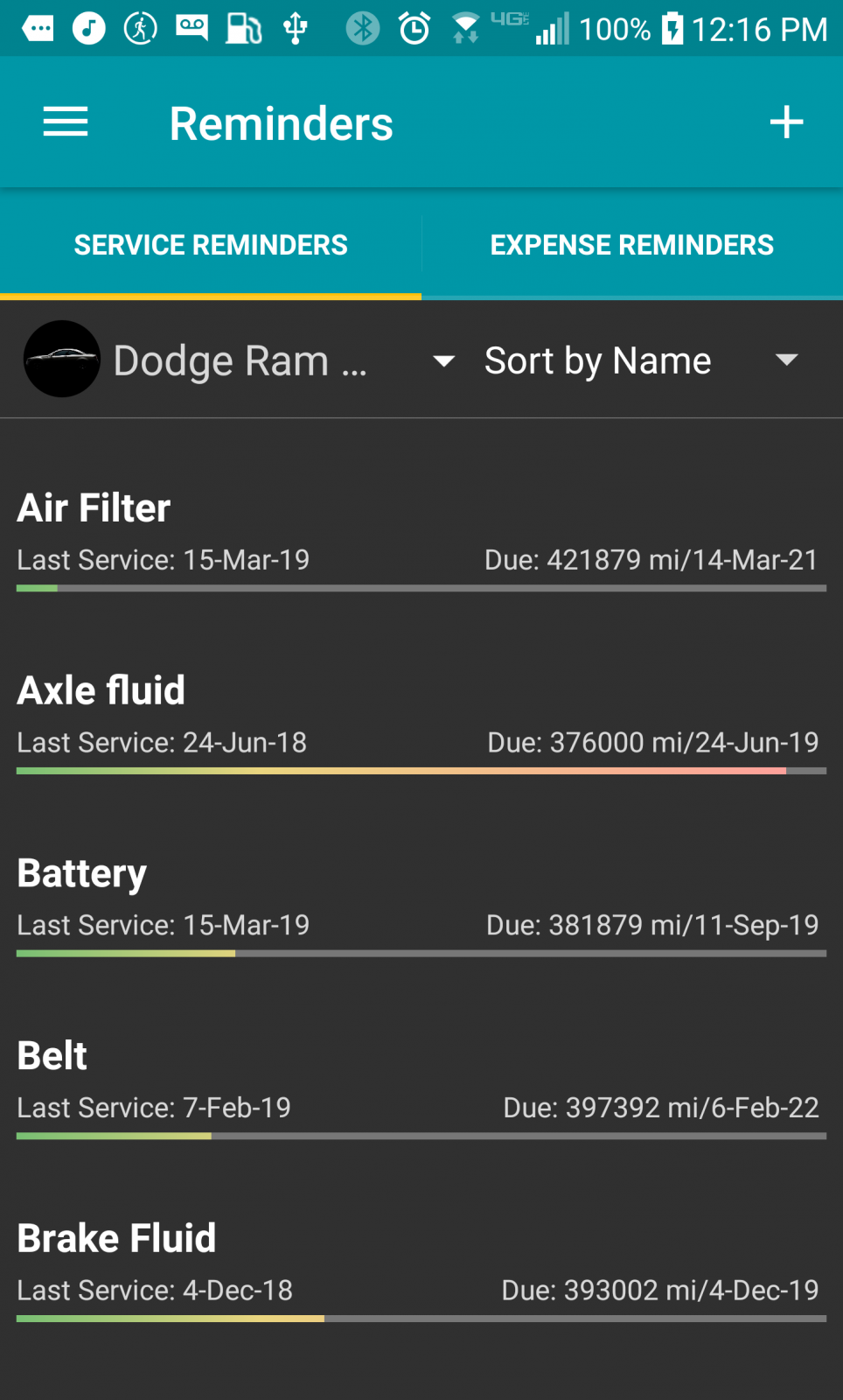
ECM CANBus can't report higher than 204*F and then flips to -40*F which is normal. ECM CANBus is limited to 00 to FF in Hex. Which in decimal displayed is -40*F to +204*F span if you add zero there you have 255. You need an app called Simply Auto for your phone so as you track the fuel mileage it reminds you to service different things.
-
I've already told MoparMom this winter I plan on assembling those things and getting them on the deck for use. Why have something brand new in the box and not use it?
-
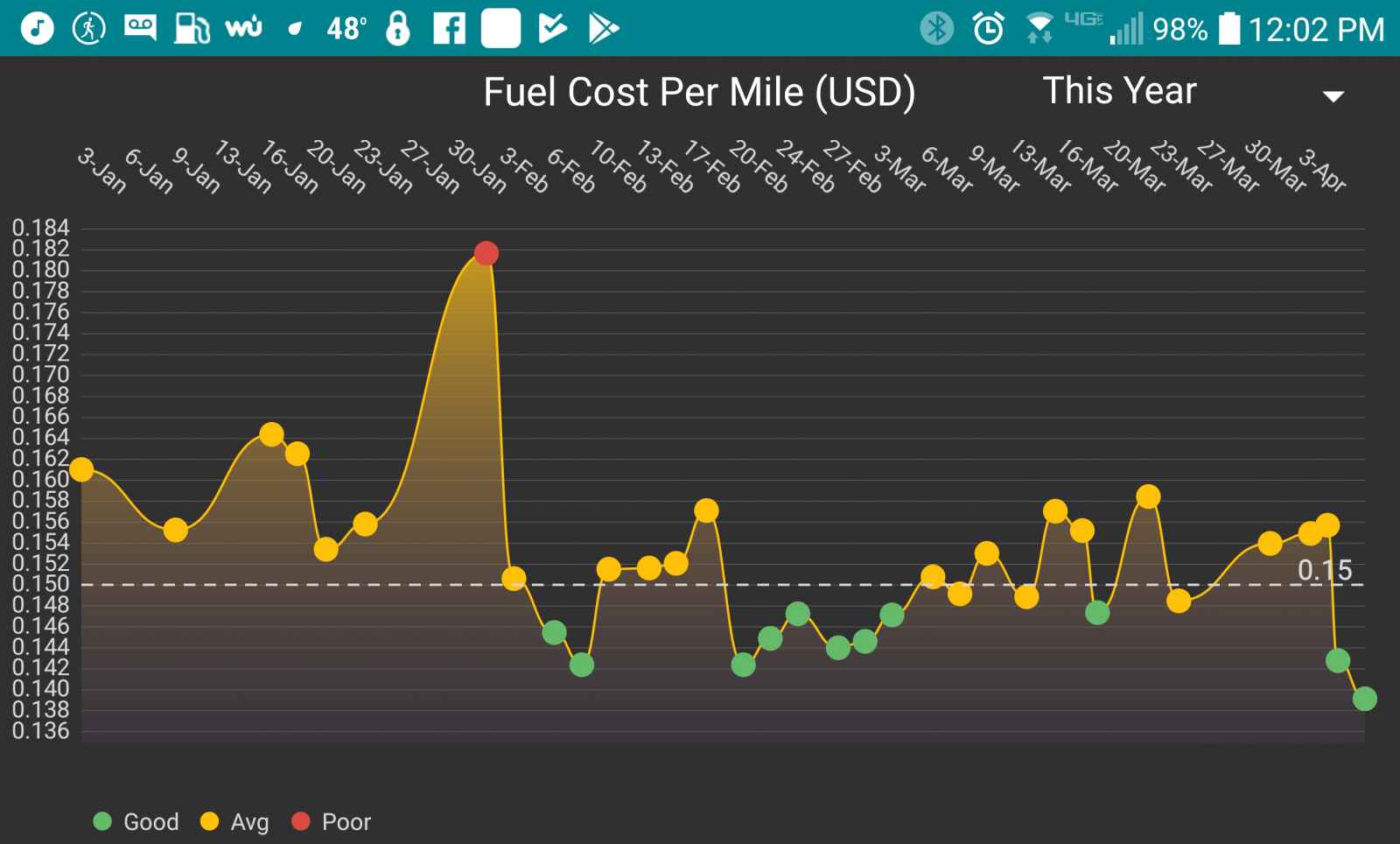
As for the ABS light that is typically the front speed sensors. Replace both as a set. Being your speedometer is working in the photo I'm going to suggest the front sensors. I just happen to have 2 sets of sensors on hand (used very low miles). If that doesn't fix it the tone ring is damaged in the unit bearings and will need to have both bearings replaced. As for the MPG's you need to report the engine load numbers at 55, 65, and 75 MPH. I want to see how much fuel your commanding. As for my own setup just checked my MPG's for this last tank and got 20.84 MPG. Finally pushed the cost per mile down in the 13's cents per mile. Over 4 cents cheaper a mile than my 1996 Dodge 1500 V8 5.9L.
-
In just 3 days I've clocked over 800 miles. This tank I'm figuring 21 to 22 MPG. 7 x 0.010 injectors and Quadzilla. It will be worth it to follow along for tour weekly mileage.
-
How about a failed 12V fuel solenoid relay. That is the only thing I've seen with contacts that big. (Hint... Look at the forum its posted in... )
-
2 years ago I did a clutch just near New Years on my truck and that sucked still being the shop floor is still cold. The wood stove cranked up so when you stood up your about fried to death in 80 to 90*F room temp. The raced to get back to where it was cool on the floor.
-
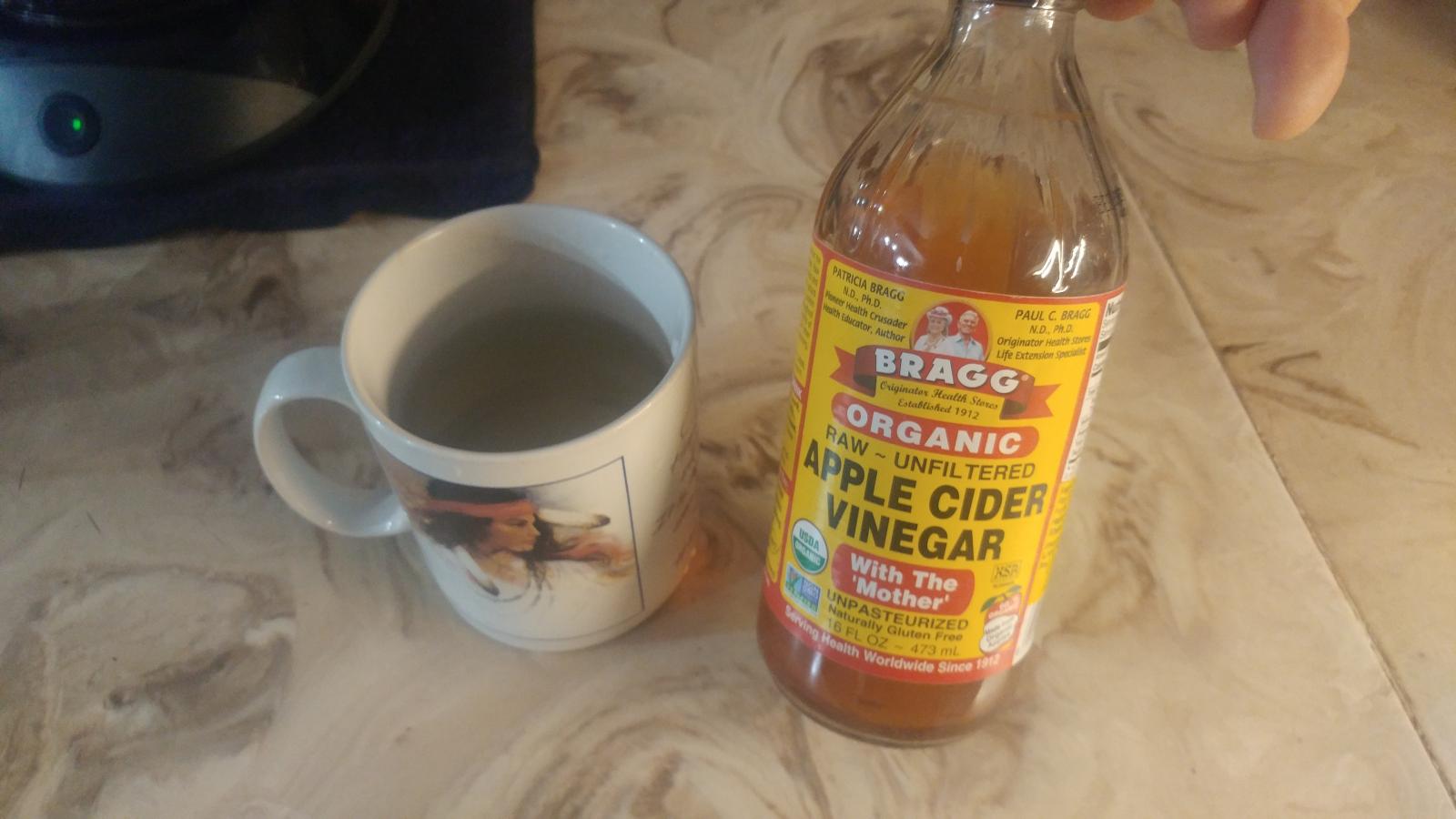
I've gotten used to drinking an 8 oz mug of water and apple cider vinegar with 2 cap fulls.
-
I'm trying to get @IBMOBILE-JEN to jump in the mix too. She is a wealth of knowledge. She is a very intelligent person with herbalistic healing.
-
I'm doubtful. I've seen guys pull bread truck engines and stuff them in Dodge body. They look the same and typically no big differences. The only thing is the Dodge ECM and PCM has to be used. The VP44 itself is a dumb pump. The PSG unit on the pump only has 3 jobs. Set fuel amount (duration) Set timing (BTDC degrees) Report any errors back to the ECM.
-
I've got brand new dual fuel smoker, cowboy Grill brand new in the box. Just lack the time. 39 hours a week driving.
-
The key number is stamped on the body of the pump and the key itself. It can be checked but it means removing the pump to see the numbers.
-
This is the first time I've seen this comment. Way too many jumps on the synthetic bandwagon and attempt to extend out too far and cause more damage than the old petroleum based oils. Because of the enhanced cost of synthetic oils, most people are more prone to keeping the oil in service longer than it should. Regardless you need to check the fluid condition, color, smell, etc. Then make it a point change the fluid in something isn't right. Don't attempt to hang on to expensive synthetic fluids than are possibly washed out.
-
Let's see what you report. Make sure to check the RPM with a fully warmed engine.


