Mopar1973Man
Owner
-
Joined
-
Last visited
Everything posted by Mopar1973Man
-
Mine slobbers like that near the rear of the control arms. Totally normal. I might lose less than a pint of oil in 10k miles.
-
Yeah, that is one thought about cleaning the frame off of salt...
-
HID are the best solution for vehicle lighting bar none. Please do not consider LED headlight unless you willing to do Morimoto LED's where are just as expensive. I got mine from Retro Shop. https://shop.retroshop.us/ProductDetails.asp?ProductCode=2G.RAM.RETRO Then I installed PIAA LED's driving lights. Those aren't cheap either but super bright. Brighter than the Morimoto HID's http://www.piaa.com/store/p/146-LP-530-Fog-LED-Light-Kit.aspx Then the front marker lights in a switch back bulb... https://www.superbrightleds.com/moreinfo/tail-brake-turn/3157-switchback-led-bulb-dual-function-60-smd-led-tower-a-type-wedge-retrofit-car/1916/4478/ Now I'm highly visible and plenty of light to see in the worst conditions.
-
Yeah when I got better conditions to check.
-
Every tow my RV barely seen 130°F in transmission temp. Engine load on flat ground is reduced from the past to 25%. Really reduced temperatures all the way around with 30 inch tires.
-
Being that I typically run at 15 to 19% engine load less torque and cooler fluids. My engine idles at 11 to 12% very low torque required. Thus why my transmission struggles to rise to 130°F.
-
I'm not a fan of catch cans being they are no better than the factory plastic bottle slobbering all down the front of the engine. People forget to drain them on a schedule then end up with the same problem all over again from the stock plastic bottle that didn't work then and still doesn't work now. Just another mess maker... This is why I removed mine long ago. If you install a catch can with a filter the filter will plug eventually from the oil vapors and then still blow the tappet gasket or crank seals. Best leave it open pipe to drip on the road than attempting to catch it.
-
When to worry... This is excessive blowby. Now to drip now and then is normal. As long as you don't lose a massive amount of oil then anything to worry about. Blowby test is junk in my opinion. You can have a cracked piston and still pass a blowby test. The only true test is compression or leak down testing. Skip 1the blowby way too many people end up passing with problems.
-
Kooskia ID... Moscow, ID Pollock, ID New Meadows, ID
-
With all the trailer towing and mileage I put down I've never had a differential issue as of yet as I head towards 400k miles. I really doubt that a simple cover is going to impact the temperature much. If there are already issues that is creating excessive heat like most add the big tires, oversized wheels, and lift kit adding wind drag that put more leverage load on the gears and differentials. When someone like myself that went down in tire size and reduced the amount of differential loading. Naturally, my differential temperatures are much lower without the fancy aluminum cover. I see the cover being a bandaid to a bigger problem like oversized tires on 3.55 gear which will increase differential temperatures. Fix the inefficiencies and temperatures will naturally fall without any fancy coolers and covers. The rise in temperatures is a sign of wasted energy resulting in generating heat.
-
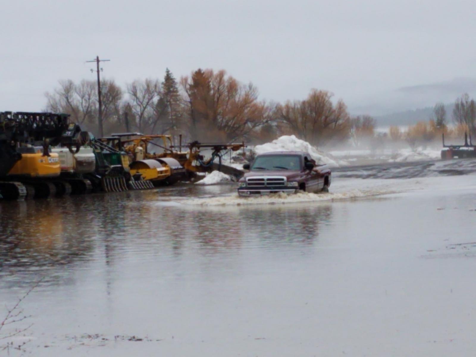
I'm glad I got out. Just found out this morning from a friend in Riggins power is out and so is the internet. The river came up enough to wipe out bridge in the canyon. The debris backed up and undermined a power pole. I've been warned the roads are not safe at the current time. We are safe here in Parma, ID. Even in Weiser the river closed US95 and you have to take 201 to get back to Idaho. 55 is open but lots for rock slides and mud slides. We are just going to hole up in Parma for now. Just made contact with @IBMobile and @IBMOBILE-JEN and let them know how I'm doing. I'm being informed by many up in my home area that it just not safe to return. Weather back home is continual rain till most likely next Tuesday. MoparMom will be able to continue here dialysis treatments and we have shelter and food. Big thanks go out to @Smarty Support and Gary & Mary that let me park on there land to stay with the RV.
-
Gave up on outerwears... When the filter last over 100k miles without the outerwear.
-
Did you bench test you new alternator? Are you sure you have a good alternator. You can unplug the field lead and test drive it.
-
Highway was flooded from New Meadows to Council. Anywhere from a few inch to nearly foot of water. Lots of mud and rock slides. I've got the RV down in Parma and in good shape.Alternator is marginal at 0.075. I would replace the alternator or diodes. Then do the W-T ground mod.Well we will see. Ill have the batch by Friday.Thanks... Ill be careful and see what happens. It got to be better than bulbs now that continue to melt the lens in my bedroom. Ugh...Ummm... Puddle jumping... No issues.
 Let me mention one thing here. If you need diff covers for ditching the heat in the fluid you might look at what is causing the heat. When there is inefficiency somewhere getting the power to the ground the object will create a huge amount of heat. When your reducing drag and inefficiency, you will reduce the amount of heat produced by the device. Then there is also a requirement for lubricants to gain a certain amount of heat for optimal running also so the fluid can vaporize any moisture. Just something to think about.It's 6:22am here... Rained another 0.5 inches early this morning. My neighbor down the road has spent the evening sandbagging homes in New Meadows. It's up to 8.2 feet in the Little Salmon River and flood stage is 10.0 feet. It's time to get out of here.Never collapse at 135k of dirt road travel.Every thing is done on the mobile device. You can even adjust while rolling but not suggested for safety reasons. No PC required for tuning. The PC is only required for firmware updates.Bingo... Thanks for confirming what I was thinking!You might do a search for Gale Bank Diff Cover testing and watch all the videos. There is a bunch of info to at least listen to and look at. https://www.google.com/search?q=gale+bank+testing+diff+covers&oq=gale+bank+testing+diff+covers https://www.alligatorperformance.com/info/blog/post/banks-power-prototype-rear-diff-cover-video-and-pictures-inside