


Mopar1973Man
Owner
-
Joined
-
Last visited
Everything posted by Mopar1973Man
-
I don't care who you are that is a killer looking truck even with the tip. don't feel bad I've got a 5-inch tip hanging out that side too.
-
Gotta ask did you tighten the injectors hold down first or the cross over tubes first?
-
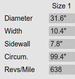
99.4 inches... Circumference...
-
Well... I guess that is a dud... I'm still playing with old 90's V8 engines.
-
LEDs (Light Emitting Diodes)... Some diodes don't like AC power banging away on them. The reverse current creates a huge amount of heat. This is what burned it up.
-
245/75 R16 empty truck 20.84 MPG, when towing my RV 14.93 MPG. (recent numbers) My 66 MPH is exactly 2,000 on the tach and this thing climbs mountains like a beast. Even the RV back there it doesn't slow down and doesn't get hot.
-
If you could back probe the plug which I'm pretty sure you can't do. That would be the way to measure voltage. One way I really don't like is to take a sewing needle and push it into the wire as a test point. Then measure with a DVM. Afterward wipe a small amount of silicone in the needle holes.
-
Wow. That 3rd Gen write up worked on the 2nd gen hood. Oh please share the details. I want to know what you ordered for parts.
-
Quadzilla only maths out the shift based on the speed. If you don't have your tire size set up right then the speed shows wrong and the gear is going to show wrong.
-
62/68/12 would be a good turbo. Even my 60/60/12 is holding up to the abuse of the Quadzilla and 7 x 0.010 injectors. You will be soon you just jinx yourself. I did the same thing ran around with 45 PSI boost and finally about 6 months later the coolant jacket blew out in the back of the head. It just best to do the ARP studs and no worry about the head gasket. Stock bolt will stretch even in stock fuel. ARP studs are a different tinsel strength to prevent the stretching.
-
Ok, let us get science into the answer then. Grab an IR temp gun and measure turbine housing after a good run and report the temperature.
-
Actually no. That's not true. They would have replaced the alternator and found it doesn't charge then grab the other write up and install an external regulator and go on. Now you can add the newer mod and never worry about the PCM failing.
-
Good to go on the injectors. Still up there. It when the engine load drop below 5% and idle speed is 825 RPM and higher.
-
Your welcome (under my breath - That suxed...)
-
Better stability compared to the SAC. At least in my experience, the first set of SAC 7 x 0.0085 injectors had a nasty stalling issue and very lopey. Now with the 7 x 0.010 @ 320 bar they got a very mild lope but smooth at an idle. Doing the tune work for higher pop pressure. Stock injectors by FSM specs are 310 bar pop pressure for the injector. Most performance injectors start popping at 300 or 305 bar for flow reasons. Now which you step over to the higher side and jump to 320 bar the flow is reduced but the efficiency is increased. The fuel is atomized better and ignites easier. 320 bar will give better longevity to the injector too making them last longer. I drive a Cummins Big Cam 400 for the fire dept I know what you're talking about. As for myself, I've got 250-mile trips to do 3 days a week. I'm after the efficiency of the injector. So far I'm on my way past 20 MPG and still rising.
-
Nope. Very controllable and no real issue with EGT's on my last tow which was a 8,000 pound 31 foot Jayco RV. This includes climbing grades at 6% and 7% not a problem. 14.93 MPG for towing the RV from New Meadows, Idaho to Parma, ID. I've got to work on the tuning tune a bit more I'm sure I can make it work awesome. Injectors are DAP VCO (7 x 0.010 @ 320 bar) which is different from your Ducky Fuel Injection (7 x 0.009) popped at most likely 305 bar.
-
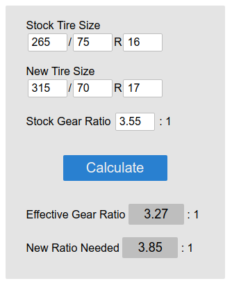
285's isn't going to be optimal either. Still puts you at 3.44 on the final. Need to go smaller yet. This will impact the EGT's still not as bad but you still adding quite a bit of rolling resistance. Even with 285's you would be optimal if your re-gear with 3.73 gears. More on rolling resistance... http://hpwizard.com/rotational-inertia.html
-
Cooldown still applies to any turbo including smaller turbos on a gasoline engine. The turbo bearings can coke up from the excessive temperatures at shut down. The only reason a deal would void the warranty is that racers tend to use the pyrometers to watch for excessive cylinder temperatures and meltdown.
-
Gear ratio. Strictly gear ratio and tires are too big and adding way to much engine load. I've got the tune dialed into the point I can WOT all the way to 100 MPH and never reach 1,200*F. But then again I'm running a mere 30-inch tire but the ratio is correct. Might look cool but your just going to burn it down with those huge tires. The only way to keep those tires is to re-gear the axle with 4.10 gears.
-
Gear ratio is wrong and too low. Need to re-gear the axles or change out the tires. You'll need 31-inch (3.55) or 30-inch (3.69) tires for optimal ratios. EGT will naturally fall with ratios between 3.55 to 3.73. My current tune would cover you for the Daily Driver. My turbo is slightly bigger (60/60/12). I'm already running 7 x 0.010 injectors but mine are popped at 320 bar for economy purpose. I'm 1,800 feet to 5,000 feet typically. I'm going to release another version here soon. Being summer fuel is in full swing and I can run even more timing. I just tested to see how much timing I can run. I'm pretty well maxed out now.
-
The article goes over the voltage and grounds. Then while testing with a DVM you will test for shorts to ground and open wiring.
-
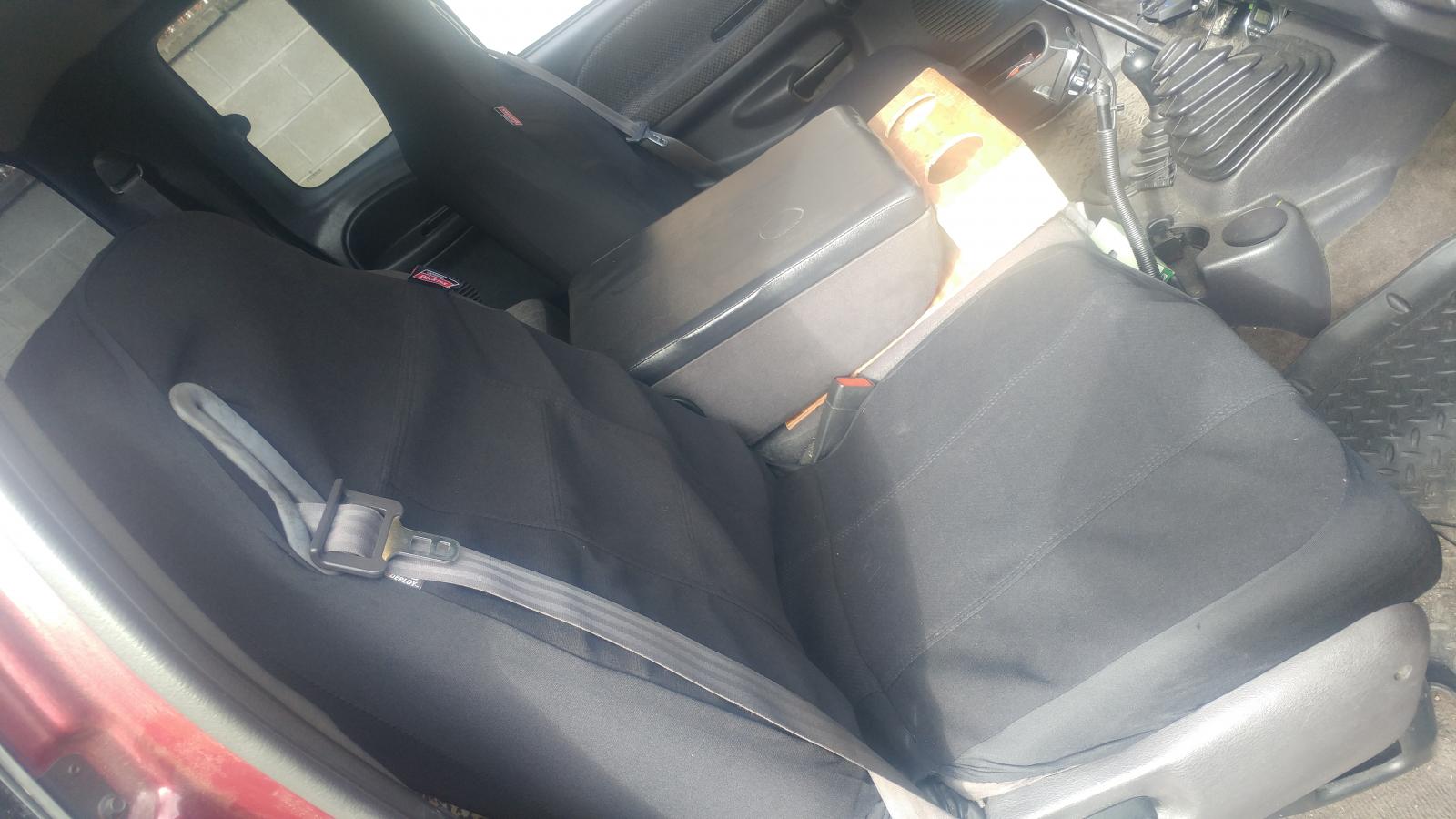
Done it again another set of cheap WalMart seat covers and made them fit like they were meant too. I'm good for another 100k miles again! I got a set of Dickies Seat Covers and with a bit of trim work for the seat belt, they look great!
-
Timing is too retarded for few revving typically. Even my truck will do the same thing this is totally normal.
-
I was just looking at the number of times my system has been dry and the reprimed. The snubber is at the tap point not at the sensor/gauge. So the chances of water being in contact with the snubber is a good chance. This depends if the truck has the factory fuel filter or not. Then if the addon fuel system has a water separator or not. I'll admit even mine has had some water at the AirDog but nothing at the stock filter can. Like my fuel up here is drier than most where biodiesel has more water because of washing the fuel. Then southern states with high humidity have had algae issues which is water in the fuel issue again. Just thinking a wider scope that all.
-
You didn't do the P0237 testing, did you? This is not a Quadzilla fault but a wiring fault. Possible Causes Other DTCs Boost Pressure Sensor 5-volt Supply Circuit MAP Signal Circuit Short To Ground MAP Signal Circuit Short To Sensor Ground MAP Sensor Intermittent Wiring Problem ECM 1. Turn ignition on with engine off. Using DRBIII(R) scan tool, check for engine DTCs. If any 5-volt supply circuit DTC(s) exist, perform appropriate test. See DIAGNOSTIC TROUBLE CODE DEFINITIONS . If no 5-volt supply circuit DTC(s) exist, go to next step. 2. Start engine and allow engine to idle. Using scan tool, read MAP sensor voltage. If MAP sensor voltage is .2 volt or greater, go to next step. If MAPsensor voltage is less than .2 volt, go to step 4 . 3. Shut engine off. Turn ignition on with engine off. Using scan tool, read MAP sensor voltage. If MAP sensor voltage is less than 2.35 volts, go to next step. If MAP sensor voltage is 2.35 volts or greater, go to step 9 . 4. Turn ignition off. Perform turbocharger boost pressure test. See TURBOCHARGER under AIR INDUCTION SYSTEMS in SYSTEM & COMPONENT TESTING - RAM PICKUP - DIESEL article. If boost pressure test passes, go to next step. If boost pressure test does not pass, repair as necessary. 5. Ensure ignition is off. Disconnect MAP sensor harness connector. MAP sensor is located on driver's side rear corner of cylinder head. Turn ignition on with engine off. Using DVOM, measure voltage at terminal No. 1 (Orange wire) on MAP sensor harness connector. If voltage is 4.7-5.3 volts, go to next step. If voltage is not 4.7-5.3 volts, repair Orange wire between ECM and MAP sensor. ECM is located on driver's side of engine, just in front of fuel transfer pump and contains a 50-pin connector. 6. Turn ignition off. Ensure MAP sensor harness connector is still disconnected. Disconnect ECM harness connector. ECM is located on driver's side of engine, just in front of fuel transfer pump and contains a 50-pin connector. Using DVOM, measure resistance between ground and terminal No. 2 (Gray/Red wire) on MAP sensor harness connector. If resistance is 1000 ohms or greater, go to next step. If resistance is less than 1000 ohms, repair short to ground in Gray/Red wire between MAP sensor and ECM. 7. Using DVOM, measure resistance between terminal No. 3 (Black/Light Blue wire) and terminal No. 2 (Gray/Red wire) on MAP sensor harness connector. If resistance is 1000 ohms or greater, go to next step. If resistance is less than 1000 ohms, repair short between Black/Light Blue wire and Gray/Red wire. 8. Turn ignition off. Reconnect ECM harness connector. Using scan tool, read MAP sensor voltage. If MAP sensor voltage is greater than 4.5 volts, replace and program the ECM. See appropriate REMOVAL, OVERHAUL & INSTALLATION article. If MAP sensor voltage is 4.5 volts or less, replace MAP sensor. See appropriate REMOVAL, OVERHAUL & INSTALLATION article. 9. Turn ignition off. Visually inspect related wiring harness. and connectors between MAP sensor and ECM. Look for any chafed, pierced, pinched or partially broken wires. Visually inspect MAP sensor harness connector and ECM harness connector for broken, bent, pushed out or corroded terminals. Check for any Technical Service Bulletins (TSB) that may apply. Perform a wiggle test on the related wiring harnesses with the ignition on, engine not running. Repair as necessary. If no problem is found, test is complete.


